
ELVOX 68IAR - Video Intercom Vimar - Free user manual and instructions
Find the device manual for free ELVOX 68IAR Vimar in PDF.
| Product type | Video door phone kit (video intercom) |
| Brand | Vimar |
| Model | ELVOX 68IAR (Art. 68IA/R or 68IA/RC) |
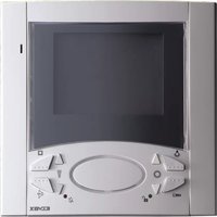
| Monitor screen | Black and white: CRT 4" (Art. 6029); Color: TFT LCD 3.5" (Art. 6029/C) |
| Camera type | CCD 1/3" with manual tilt |
| Video resolution | PAL 625 lines, 50 frames/s |
| Power supply | 110-240 VAC, 50/60 Hz, max consumption 15 W |
| BUS output voltage | 28 VDC nominal (SELV) |
| Max distributed current | 1.6 A (1 A continuous + 0.6 A intermittent) |
| Street panel dimensions | 80 x 120 x 25 mm (overall) |
| Wall monitor dimensions | Approximately 140 x 115 x 65 mm (power supply) |
| Kit weight | Approximately 1.5 kg (estimate) |
| Operating temperature | Camera: -5°C to +45°C; Monitor: 0°C to +40°C |
| Number of buttons | 5 buttons (door release, auto-switch-on, 3 intercom) |
| Main functions | Video call, intercom, remote door opening, auto-switch-on, intercom between stations |
| Maximum cable distance | 150 m between furthest devices, total 500 m max |
| Recommended cable type | Art. 732H or 732I (2 x 1 mm²) |
| Installation | Flush or surface mounted (panel), wall mounted (monitor) |
| Maintenance and cleaning | Use a soft, dry cloth. Do not use solvents. |
| Safety | Installation by a professional. Provide a bipolar switch upstream. |
| Spare parts | Accessories: relay Art. 170A/101, Art. 682R, chime Art. 860A, etc. |
| Repairability | Contact a Vimar approved service. Contact technical support. |
| Standards | LV Directive, EMC, EN60065, EN61000-6-1, EN61000-6-3 |
Frequently Asked Questions - ELVOX 68IAR Vimar
User questions about ELVOX 68IAR Vimar
0 question about this device. Answer the ones you know or ask your own.
Ask a new question about this device
Download the instructions for your Video Intercom in PDF format for free! Find your manual ELVOX 68IAR - Vimar and take your electronic device back in hand. On this page are published all the documents necessary for the use of your device. ELVOX 68IAR by Vimar.
USER MANUAL ELVOX 68IAR Vimar
natural_image
Line drawing of a rectangular electronic device with a scroll wheel and ventilation slots (no text or symbols)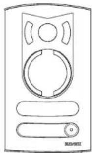
natural_image
Line drawing of a device with circular ports and a handle (no text or symbols)68IA/R, 68IA/RC
natural_image
Close-up of hands installing a black electrical component with two screws, labeled Fig.14B (no text or symbols on the device itself)
ALIMENTATORE (Art. 6922.1)
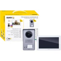
Petrarca series B/W video door entry kit for single-family installations, comprising: 1 1300 series entrance panel in electro-polished anodised aluminium for flush or surface wall-mounting with 1 call button (type 13K1), complete with pan/tilt camera with speech unit (type 68TU/K), and 1 additional key (type R131) for converting the entrance panel for two-family kits, 1 Petrarca series surface wall-mounted door entry monitor with low-profile 4" B/W screen (type 6029 + 62I8), complete with fixing plate (type 6145), 1 power supply unit (type 6922.1). The interphone is supplied with 5 push-buttons (1 for door lock release, 1 for self-start and 3 for intercom calls). The kit can be expanded to include up to 2 external entrance panels with a maximum of two calls and 4 monitors/interphones.
Type 68IA/RC (colour videokit)
Petrarca series colour video door entry kit for single-family installation, comprising: 1 1300 series entrance panel in electro-polished anodised aluminium for flush or surface wall-mounting with 1 call button (type 13K1), complete with pan/tilt camera with speech unit (type 68TC/K), and 1 additional key (type R131) for converting the entrance panel for two-family kits, 1 Petrarca series surface wall-mounted door entry monitor with 3.5" TFT LCD colour screen (type 6029/C + 62I8), complete with fixing plate (type 6145), 1 power supply unit (type 6922.1). The interphone has 5 buttons (1 for door lock release, 1 for self-start and 3 for intercom calls). The kit can be expanded to include up to 2 external entrance panels with a maximum of two calls and 4 monitors/interphones.
INTERCOMMUNICATING INTERPHONE FOR 2-WIRE VIDEO-KIT
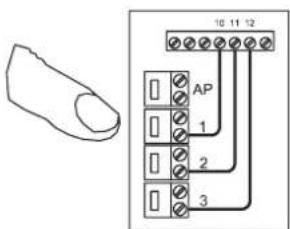
Type 6218 is an interphone in the Petrarca series for intercommunicating versions of the 2-wire video kitswith monitor Art. 6029 (6029/C) by means of bracket type 6145 or desk-topversion type 6142. Supplied with 5 push-buttons, one for door lock release, one for self-start of the interphone in system, even when not called, and 3 push-buttons for intercom calls; another 2 push-buttons can be added for auxiliary services. The interphone can be combined with type 6153/682 for call volume adjustment and for call denied/door lock open signals. The interphone is supplied with 3 push-buttons for intercom calls. To exclude the intercom function, disconnect the push-buttons from the respective terminals (10, 11, 12).
Connection terminal board
4) Additional pushbutton common
8) Auxiliary service 1 (enables activation of relay type 682R).
9) Self-activation
10) 1st intercommunicating call.
11) 2nd intercommunicating call.
12) 3rd intercommunicating call.
13) Auxiliary service 2 (enables activation of relay type 682R).
1, 2) BUS line.
4, 6P) Connection for door call pushbutton.
5, 6S) Connection of additional door ringtone Type 860A (see variant).
-, +) Additional supply voltage only by type 6923.
They are used if the simultaneous activation of two or more monitors is required (maximum 4 monitors).
Video) Connector for connection of monitor type 6029 (6029/C)
Controls and adjustments
The call volume can be adjusted by moving the loudspeaker wirefrom connector A+ to A-; otherwise use accessory type 6153/682.
Carratteristiche tecniche del monitor in B/N Art. 6029
- Surface wall-mounted monitor in ABS.
- Surface wall-mounted monitor with flat screen Kinescope CRT 4" in B/W.
- Standard video signal CCIR 625 lines, 50 images
- Operating temperature: 0^ to +40^ C
- Surface wall-mounted monitor in ABS.
- Slim-line surface wall-mounted monitor with 3,5" LCD TFT colour screen
- Video signal standard: PAL type G.
- Operating temperature: 0° to +40°C
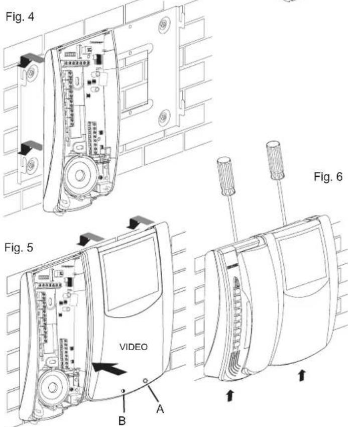
Controls (see fig. 5)
- Brightness adjustment using control "A".
- Contrast adjustment using control "B".
INSTALLATION MONITOR WITH INTERPHONE
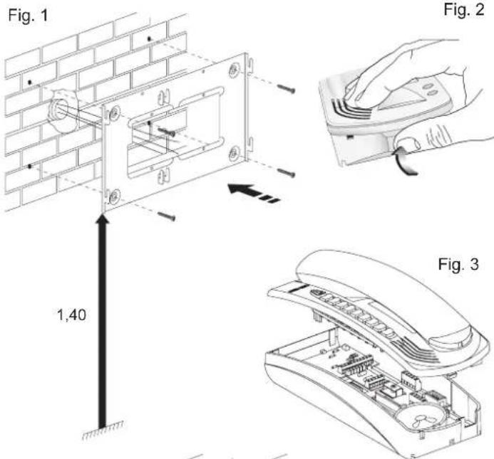
Fig. 1 - Fix the bracket type 6145 to the wall at a height of approximately 1.4 m above the ground.
Fig. 2 - 3 Open the interphone, split the cover from the bottom making pressure on the lower side of the cover
Fig. 4 - Fit the base of the interphone into the appropriate seats to the left of the bracket. Slide the base of the interphone downwards until it is completely fastened. Connect the wires to the terminals of the interphone and monitor card.
Fig. 5 - Connect the wiring of the monitor to the connection card by means of connector CN1 on the card.
Fit the monitor in the appropriate seats in the bracket. Slide the base of the monitor downwards until it is completely fastened.
Fig. 6 - Close the interphone by hooking the cover onto the base and pressing the bottom of the cover until it clicks shut. To remove the interphone or monitor from the bracket, press the safety tab with a screwdriver in the direction of the arrows.
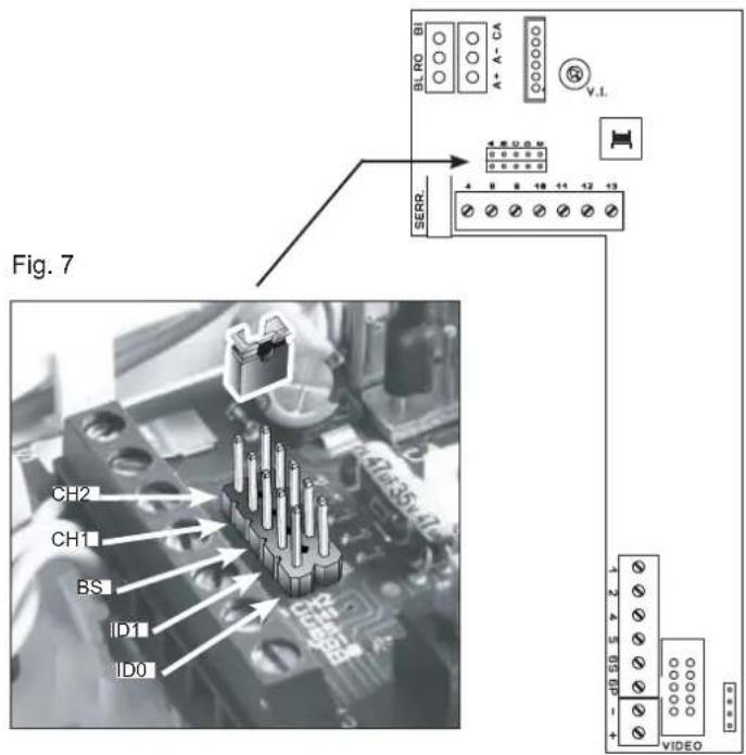
Configuration of interphone type 6218
The operation of interphone type 6218 is controlled by setting 5 contacts in the interphone. Insert or remove the jumpers supplied with the interphone to activate the functions. Configuration must be carried out before powering up the installation.
The possible settings are as follows:
- Interphone ID code
- Intercom call programming
- Lock release
- Associate panel call button
- Phone identification code
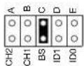
When the installation contains multiple interphones, they must be identified by means of different codes. The ID code is assigned by inserting the jumpers in contacts D (ID1) and E (ID0) as indicated in the figure.
- Intercommunicating call programming
The intercom call push-buttons (terminals 10, 11, 12) are configured when assigning the interphone ID code, by setting the jumpers as indicated in the following table.
| Caller identification code (n°) | 1 2 3 4 | |||
| Terminals | Call receiver identification code (n°) | |||
| 10 2 1 1 1 | ||||
| 11 3 3 2 2 | ||||
| 12 4 4 4 3 | ||||
- Lock release
Removing the jumper of contact BS (C) from the interphone enables the door lock to be kept open continuously.. Inserting the jumper, it is possible to release the door lock from the phone only after the call or has been self-activated.
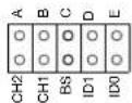
- Association of call push-button from the entrance panel
To associate the entrance panel push-button used for calling the interphone, use contacts CH2 (A) and CH1 (B) on the interphone: contact CH1 for the 1st button on the entrance panel, CH2 for the 2nd button if present. Inserting the jumpers the call is excluded, removing them the call and the phone activation is enabled.
Intercom interphone operation
Using the door entry unit as an intercom Interphone/monitor type 6218+6029 (6218+6029/C) can call other type 6218+6029 (6218+6029/C) interphones or type 6308 (6328/C) monitors according to the table shown above, but type 6308 (6328/C) monitors cannot call type 6218 interphones.
To make an intercommunicating call, lift the handset and press the intercommunicating button for the interphone/monitor to be called; the maximum duration of the conversation is 60 seconds.
During an intercom conversation (or with the handset already raised), if a call is received from an external entrance panel, the interphone rings and the intercom conversation is interrupted but the self-start button must then be pressed (without hanging up the handset) to speak with the entrance panel. The conversation time between the entrance panel and interphone can be set from 30 to 90 seconds, after which the interphone must be called from the entrance panel within 10 seconds to proceed conversation without replacing the handset; otherwise press the auto-start/self-start button on the interphone.
To activate the electric lock, press the corresponding push-button. The monitor turns off after nearly 30" (adjustable on the panel from 30 to 90 seconds).
N.B.: the intercommunicating call is generated with a different ringtone from other calls and the duration depends on activation of the call pushbutton.
The selfstart/selfinsertion push-button allows the connection of interphone or monitor to the entrance panel without being called. If there are two entrance panels on the installation, the repeated pressure of the selfstart/selfinsertion push-button switches the panel selection cyclically.
VIDEO SIGNAL STABILISATION
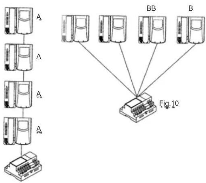
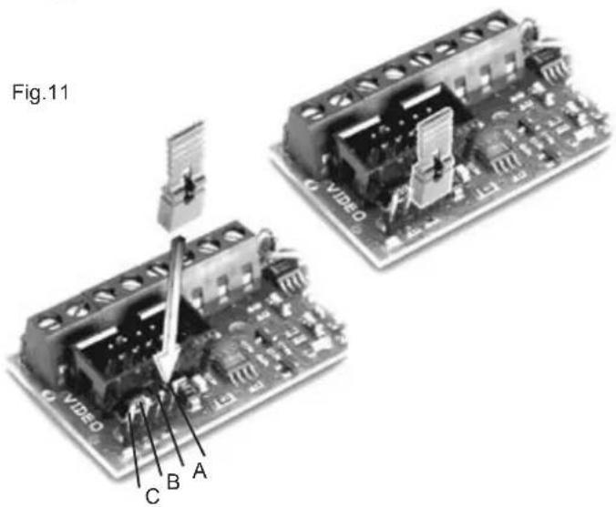
A connector and jumper are located inside the interphone for stabilisation of the video signal (see fig. 11); this jumper must be used in the following cases:
- in systems with multiple devices (interphones or monitors) connected in series. Move the jumper of the last device only to position BC and keep the other jumpers in the initial position (AB) (Fig. 9).
- In systems with multiple devices (interphones or monitors) with star connections. Move the jumpers of all devices to the position BC (Fig. 10).
- If the image on the monitor is distorted, move the jumper to one of the alternative positions from the initial one (BC or CD), to eliminate distortion.
Fig. 9
flowchart
graph TD
    A1["Server Unit A"] --> A2["Server Unit A"]
    A2 --> A3["Server Unit A"]
    A3 --> A4["Server Unit A"]
    A4 --> A5["Server Unit A"]
    A5 --> A6["Server Unit A"]
    A6 --> A7["Server Unit A"]
    A7 --> A8["Server Unit A"]

    subgraph Figure10
        B1["BB"] --> C["Computer"]
        B2["B"] --> C
    end

    style Figure10 fill:#f9f,stroke:#333,stroke-width:2px
CAMERA Type 68TU/K, 68TC/K
Camera technical features (Type 68TU/K)
- CCD 1/3" color sensor B/W
- 3.7mm F4.0 auto-iris lens with non-adjustable focus
- Automatic brightness control
- Manual traversing on the vertical and horizontal axis
- Standard video signal CCIR 625 lines, 50 images (EIA on request)
- Operating temperature from - 5° to + 45° C.
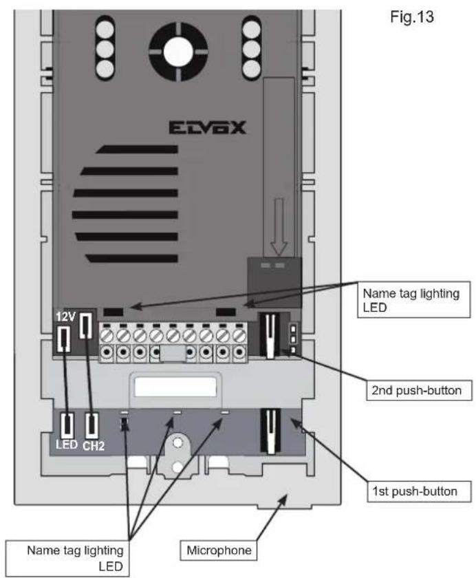
- Subject lighting by means of infrared LEDs
- Name-tag lighting through LEDs
- Built-in speech unit
- Removable terminal block
- Monitor call push-button.
- Output for control of lighting floodlight by relay type 0170/101
- Local door release control from entrance panel.
- Adjustable lock activation time (from 0 to 30 seconds).
- Supply voltage from the bus.
- External dimensions: 80x120x25 mm.
B
Camera technical features (Art. 68TC/K)
- Sensore CCD 1/3" a colori
- Obiettivo autoiride fuoco fisso 3,7mm F4,0
- Standard video signal PAL type G, 625 lines, 50 images
- Manual traversing on the vertical and horizontal axis
- Vertical resolution: 330 TV lines or Greater
- Effective picture: 512(H)x582(V) PAL
- Electronic iris (shutter)
- Video output voltage 1Vpp on 75 Ohms
- Operating temperature -5^ + 45^
- Minimum lighting level 0,1 lux
- Subject lighting by means of white light LEDs
- Name-tag lighting through LEDs
- Built-in speech unit
- Removable terminal block
- Monitor call push-button.
- Output for control of lighting floodlight by relay type 0170/101
- Local door release control from entrance panel.
- Adjustable lock activation time (from 0 to 30 seconds).
- Supply voltage from the bus.
- External dimensions: 80x120x25 mm.
Camera adjustments (Art. 68TU/K, 68TC/K)
On the camera rear side find the following adjustments:
| External volume | Internal volume | Lock activation time | Camera activation time |
 |  |  |  |
Camera terminals type 68TU/K, 68TC/K
CL, M) Connection for relay type 0170/101 for additional floodlight. (for switching on illumination in the camera's observation zone) It is activated for the time the camera is on.
CA, M) Connection for additional lock push-button.
PA, M) Connection for "open door" sensor. The sensor must be a normally open contact which closes when the door is open.
B1, B2) BUS line
S-, S+) Output for electric lock supply voltage (12V *).
V) (Not used)
* The panel supplies a current peak IT>1A for 10 mS, followed by a hold current I_M =200mA for the entire duration of the lock control.
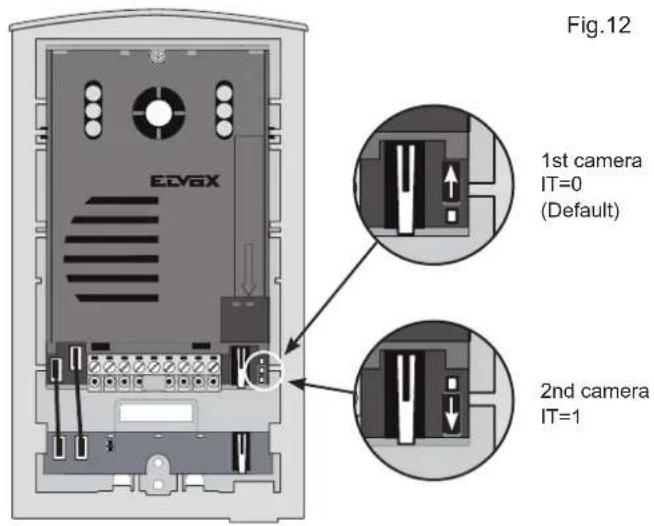
ENTRANCE PANEL/CAMERA identification code
If more cameras/entrance panels are installed on the building it is necessary to identify the cameras with a different code. The identification code is assigned by inserting the jumpers in the contacts as shown on the figure.
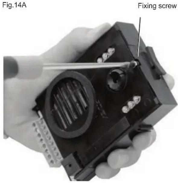
Lens orientation
Camera unit Type. 68TU/K (68TC/K) can be adjusted manually on the vertical and horizontal axis to improve the shooting angle, the screw on the upper side of the lens loosen, turn the lens in the required direction and fix the screw.
natural_image
Close-up of hands installing a component with a numbered bolt (no visible text or symbols)ENTRANCE PANEL FOR VIDEO DOOR ENTRY SYSTEMS
Before installing equipment, choose location for camera entrance panel: the camera should be protected from direct light (sun, car headlights, etc.) as this may affect the quality of the picture, and may damage the camera. It is advisable to protect panel with some form of weatherproof shelter.
The video camera is equipped with LEDs for night illumination of the subject up to a distance of 1 metre approx.
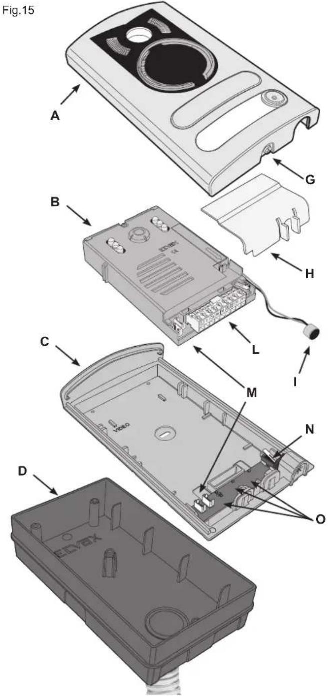
Installation of entrance panel (type 13K1), flush-mounting version
- Install the flush-mounting back box (D) on the wall with the bottom edge at a height of approx. 1.65m from the ground
- Open the entrance panel by undoing the screw under the plate (G) and detach the camera (B) from the frame, removing the light diffuser (H) and the microphone (I).
- Fit the frame (C) to the flush-mounting back box (D)
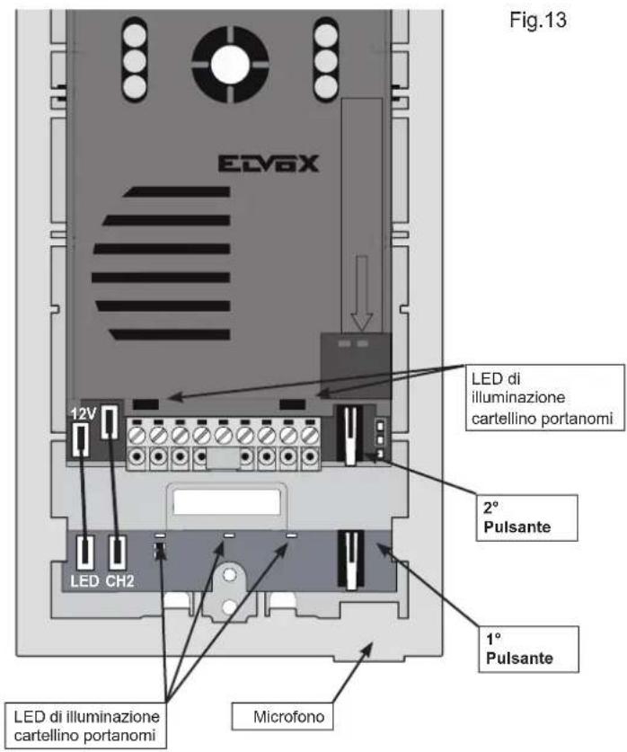
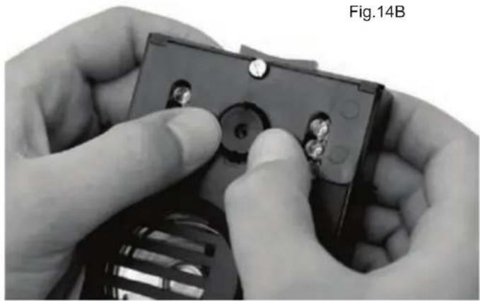
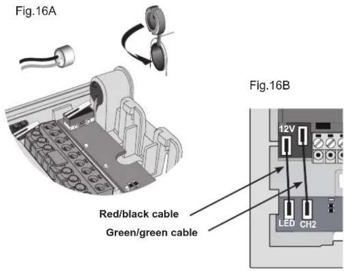
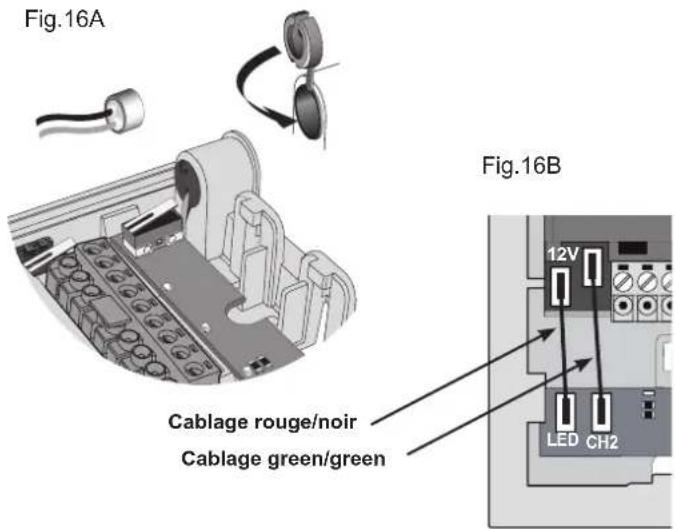
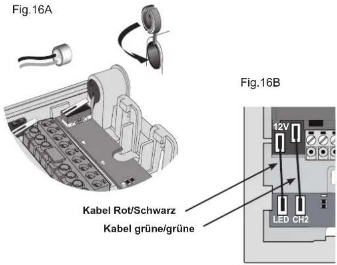
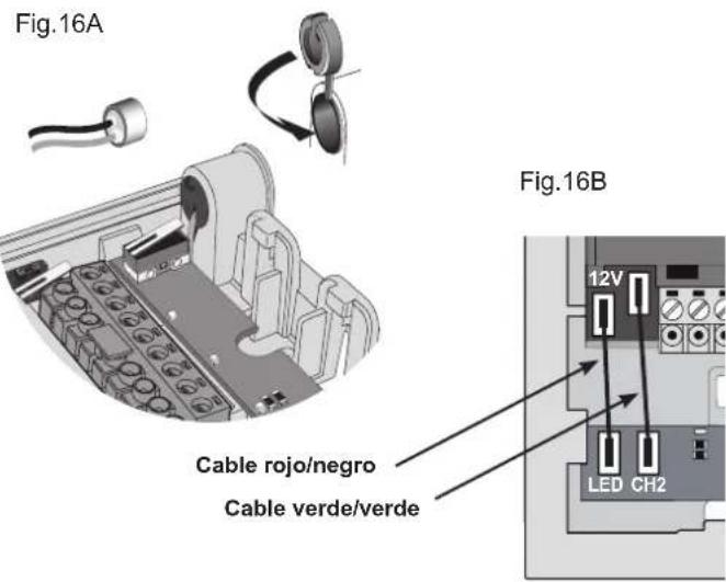
- Reposition the camera in the frame and the microphone in the special housing, refitting the plug as shown in fig.16A.
- Connect the camera to the name card lighting LED board using the two cable harnesses (harness with red/black wire for LED power supply and harness with two green wires for connection of a second call button, if required) fig.16B.
- Make the connections to the installation on the removable terminal block (L). In the case of installation for two-family video door entry systems:
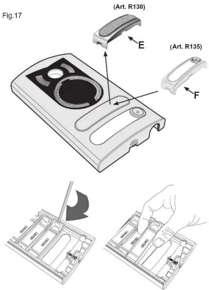
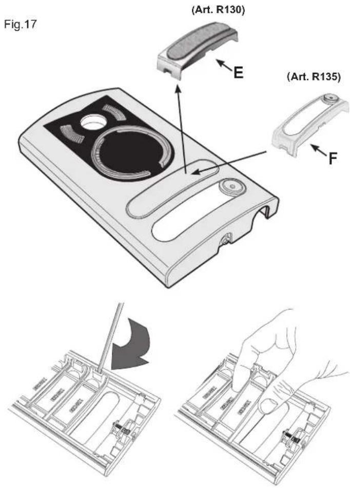
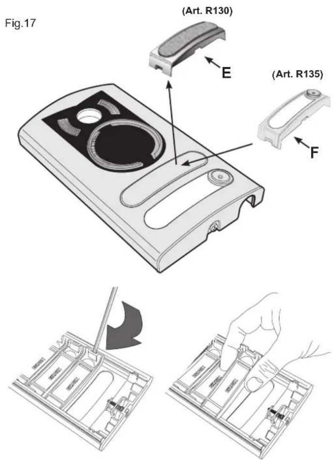
- Remove the blanking module (E) fig. 17, from the back of the plate using a screwdriver, working in sequence from bottom to top (first remove the end section, then key 1 and finally the blanking module).
- Fit the external key (F) (supplied) to the plate by pushing it lightly into place.
- Insert the light diffuser (H) to ensure even lighting of the name cards.
- Close the entrance panel, securing it to the frame with the aid of a screw-driver.

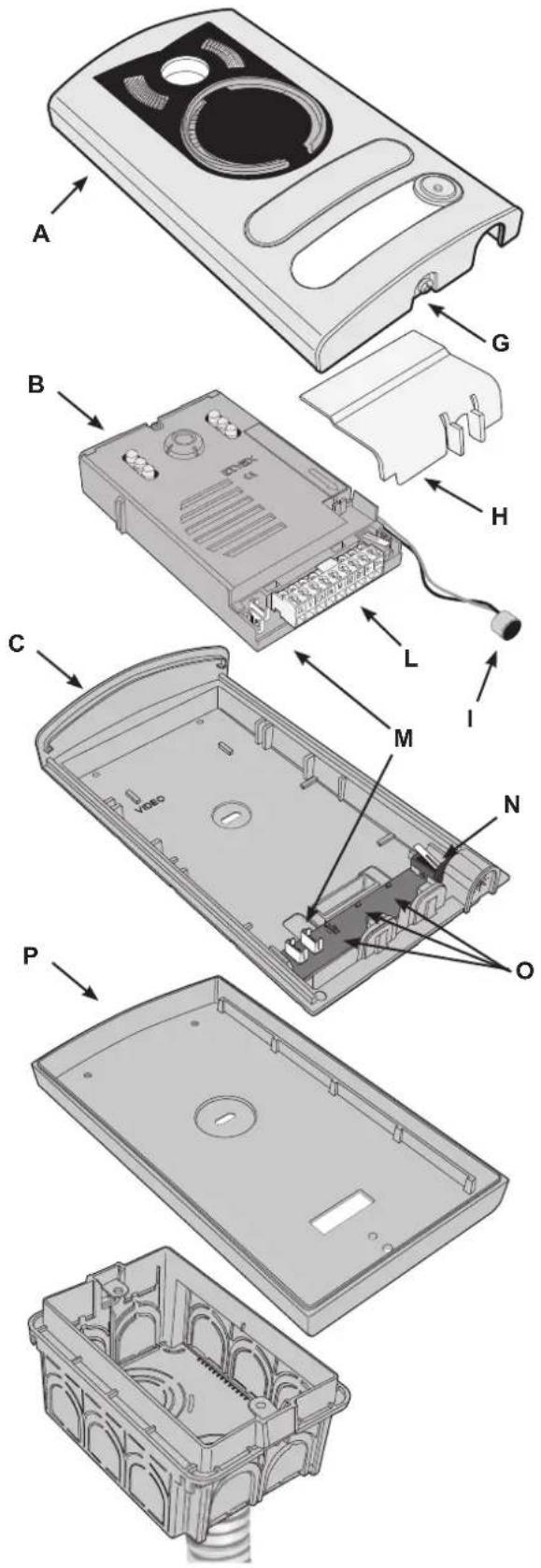
Installation of entrance panel (type 13K1), surface wall-mounting version
- Open the entrance panel by undoing the screw under the plate (G) and detach the camera (B) from the frame, removing the light diffuser (H) and the microphone (I).
- Install the frame (C) together with the surface wall-mounting back box (P) on the wall with the bottom edge at a height of approx. 1.65m from the ground.
- Reposition the camera in the frame and the microphone in the special housing (B), refitting the plug as shown in fig. 16A.
- Connect the camera to the name card lighting LED board using the two cable harnesses (harness with red/black wire for LED power supply and harness with two green wires for connection of a second call button, if required) fig.16B.
-
Make the connections to the installation on the removable terminal block (L).
In the case of installation for two-family video door entry systems: -
Remove the blanking module (E) fig. 17, from the back of the plate using a screwdriver, working in sequence from bottom to top (first remove the end section, then key 1 and finally the blanking module.
- Fit the external key (F) (supplied) to the plate by pushing it lightly into place.
- Insert the light diffuser (H) to ensure even lighting of the name cards.
- Close the entrance panel, securing it to the frame with the aid of a screw-driver.
Fig.18
POWER SUPPLY UNIT (TYPE 6922.1)
Technical specifications
- Supply voltage: 110 - 240 Vac
- Maximum current draw at 110 V 1 A
- Maximum current draw at 240 V 0.6 A
- Power dissipation 15 W
- BUS output voltage (1/2, B1/B2) 28 Vdc nominal (SELV - EN60950-1).
- Maximum current output: 1.6 A (1A continuous + 0,6A INT. with cycle 30s ON - 180s OFF).
- Operating temperature -5 °C +35 °C (indoor)
- 8 x 17.5 mm module, dimensions 140 x 115 x 65mm
- for installation in consumer units with DIN rail (60715 TH35), or wall-mounting with masonry plugs and screws provided.
Installation rules
Installation must be carried out in accordance with current regulations governing the installation of electrical equipment in the country where the products are located. Ensure minimum clearance distances all round the device in order to provide sufficient ventilation. When mounted internally of an enclosed switchboard, use a 12 x 17.5 mm module switchboard. The device must not be exposed to water drip, splash or spray.
Caution: To avoid injury, the device must be secured to the wall following the directions given in this document. The power supply must be connected to the a.c. mains by way of an easily accessible double pole switch having a gap of at least 3 mm between contacts.
Regulatory compliance
LV Directive
EMC Directive
Standards EN60065, EN61000-6-1, EN61000-6-3
WIRING DIAGRAM
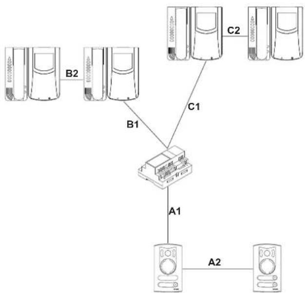
Videokit type 68IA/R (black/white), type 68IA/RC (colour)
- It is possible to reverse the polarity of the two connecting wires between power supply unit and monitor and between power supply unit and entrance panel.
- The cable recommended for connecting the kit is type 732H (2x1mm²) and/or 732I (2x1mm²). If the cable used is not one of those indicated above, the following guarantees do NOT apply.
- The installation is guaranteed up to a maximum distance of 150 metres. Distance intended as the straight-line distance between the 2 devices furthest apart (e.g. the furthest entrance panel and the furthest monitor). The total length of extended cable must not exceed 500 metres. These maximum distances apply to both B/W and colour installations.
- Electric locks connected to the entrance panels must have a maximum input current of 1 A at a voltage of 12 Vdc.
- Electrical disturbances or discharges may affect the operation of the devices. Therefore we recommend laying the cables inside separate tubes.
flowchart
graph TD
    A["Server 1"] -->|B1| B["Server 2"]
    A -->|B2| C["Server 3"]
    D["Server 4"] -->|C1| B
    E["Server 5"] -->|C2| F["Server 6"]
    B --> G["Server 7"]
    G --> H["A1"]
    H --> I["A2"]
    I --> J["Server 8"]
A1 + A2 + B1 + B2 = Max 150 m
A1 + A2 + C1 + C2 = Max 150 m
DESCRIPTION
| Codice identificativo ci-tofono chiamante (n°) | 1 2 3 4 | |||
| Bornes | Code d'identification du poste appelé (n°) | |||
| 10 2 1 1 1 | ||||
| 11 3 3 2 2 | ||||
| 12 4 4 4 3 | ||||
- Ouverture gâche
Temps activation camera


Bornes de la caméra Art. 68TU/K, 68TC/K
natural_image
Close-up of hands installing or adjusting a black electronic component with a numbered part (no visible text or symbols)INSTALLATION DE LA PLAQUE POUR PORTIER-VIDÉO
Installation de la plaque (art. 13K1) en version en saillie
ALIMENTATION (Art. 6922.1)
KAMERA Art. 68TU/K, 68TC/K

NETZTEIL (Art. 6922.1)
Technische merkmale
natural_image
Close-up of hands installing or adjusting a black electronic component with a numbered bolt (no visible text or symbols)INSTALACIÓN PLACA PARA VIDEO-PORTERO

natural_image
Close-up of hands installing or adjusting a small electronic component with a black housing (no visible text or symbols)
Connection of additional chime Art. 860A
Wiring diagram for relay Art. 170A/101 for additional bell
Wiring diagram for relay Art. 682R for stair light or other sevices powered by the mains.
TERMINALS AND ADJUSTMENT OF RELAY TYPE 682H
1, 2, B1, B2) BUS Line
1A, 1B) 1st N.O. contact, 3A 230V A.C. maximum load, for the call repetition from push-button 1 of entrance panel.
2A, 2B) 2nd N.O. contact, 3A 230V A.C. maximum load, for the call repetition from push-button 1 of entrance panel.
CONDUCTOR SECTIONS
0.75 mm ^2 section for 1 and 2 wires with 100 m maximum distance.
CONFORMITÀ NORMATIVA.
Direttiva BT
Direttiva EMC
Norme EN 60065, EN 61000-6-1, EN 61000-6-3.
Installation should be carried out observing current installation regulations for electrical systems in the Country where the products are installed.
Ensure clearance around the appliance so there is sufficient ventilation.
There must be no dripping or splashes of water on the appliance.
WARNING: To prevent injury, the appliance must be secured to the wall as described in the installation instructions.
Above the power supply there must be a bipolar circuit breaker that is easily accessible with a contact gap of at least 3 mm.
CONFORMITY.
LV directive
EMC directive
Standards EN 60065, EN 61000-6-1, EN 61000-6-3.
Power supply units constitute SELV sources in compliance with the requirements stipulated in Article 411.1.2.2 of CEI standard 64-8 (2012).

INFORMATION FOR USERS UNDER DIRECTIVE 2012/19/UE (WEEE)
In order to avoid damage to the environment and human health as well as any administra-
tive sanctions, any appliance marked with this symbol must be disposed of separately from municipal waste, that is it must be reconsigned to the dealer upon purchase of a new one. Appliances marked with the crossed out wheelie bin symbol must be collected in accordance with the instructions issued by the local authorities responsible for waste disposal.
RÈGLES D'INSTALLATION.
CONFORMITÉ AUX NORMES.
Directive BT
Directive EMC
Normes EN 60065, EN 61000-6-1, EN 61000-6-3.
INSTALLATIONSVORSCHRIFTEN.

- ALIMENTATORE (Art. 6922.1)
- Type 68IA/RC (colour videokit)
- INTERCOMMUNICATING INTERPHONE FOR 2-WIRE VIDEO-KIT
- Connection terminal board
- Controls and adjustments
- Carratteristiche tecniche del monitor in B/N Art. 6029
- Controls (see fig. 5)
- INSTALLATION MONITOR WITH INTERPHONE
- Configuration of interphone type 6218
- - Phone identification code
- - Intercommunicating call programming
- - Lock release
- - Association of call push-button from the entrance panel
- Intercom interphone operation
- VIDEO SIGNAL STABILISATION
- CAMERA Type 68TU/K, 68TC/K
- Camera technical features (Type 68TU/K)
- B
- Camera technical features (Art. 68TC/K)
- Camera adjustments (Art. 68TU/K, 68TC/K)
- Camera terminals type 68TU/K, 68TC/K
- ENTRANCE PANEL/CAMERA identification code
- Lens orientation
- ENTRANCE PANEL FOR VIDEO DOOR ENTRY SYSTEMS
- Installation of entrance panel (type 13K1), flush-mounting version
- Installation of entrance panel (type 13K1), surface wall-mounting version
- POWER SUPPLY UNIT (TYPE 6922.1)
- Technical specifications
- Installation rules
- Regulatory compliance
- WIRING DIAGRAM
- DESCRIPTION
- - Ouverture gâche
- Bornes de la caméra Art. 68TU/K, 68TC/K
- INSTALLATION DE LA PLAQUE POUR PORTIER-VIDÉO
- Installation de la plaque (art. 13K1) en version en saillie
- ALIMENTATION (Art. 6922.1)
- KAMERA Art. 68TU/K, 68TC/K
- NETZTEIL (Art. 6922.1)
- Technische merkmale
- INSTALACIÓN PLACA PARA VIDEO-PORTERO
- TERMINALS AND ADJUSTMENT OF RELAY TYPE 682H
- CONDUCTOR SECTIONS
- CONFORMITÀ NORMATIVA.
- CONFORMITY.
- INFORMATION FOR USERS UNDER DIRECTIVE 2012/19/UE (WEEE)
- RÈGLES D'INSTALLATION.
- CONFORMITÉ AUX NORMES.
- INSTALLATIONSVORSCHRIFTEN.
Brand : Vimar
Model : ELVOX 68IAR
Category : Video Intercom