
ELVOX 1282 - Video Intercom Vimar - Free user manual and instructions
Find the device manual for free ELVOX 1282 Vimar in PDF.


| Product Type | Video Door Entry System |
| Brand | Vimar |
| Model | ELVOX 1282 |
| Dimensions (Approx.) | 210 x 140 x 35 mm |
| Weight (Approx.) | 0.55 kg |
| Power Supply | 12V DC via dedicated power adapter |
| Display | 7-inch TFT color screen (approx.) |
| Camera Resolution | 720p (HD) |
| Audio | Full-duplex hands-free communication |
| Key Functions | Door release, intercom, video monitoring, call forwarding |
| Connection | Wired (2-wire bus system) |
| Mounting | Wall-mount (flush or surface) |
| Material | ABS plastic with glass front panel |
| Color | White (standard) |
| Protection Class | IP20 (indoor use only) |
| Operating Temperature | 0°C to 40°C |
| Memory | Internal storage for call log and images (approx. 100 events) |
| Compatibility | Works with ELVOX door stations and additional indoor monitors |
| Maintenance | Clean with soft dry cloth; avoid harsh chemicals |
| Safety | Low voltage operation; comply with local electrical codes |
| Spare Parts | Contact Vimar service center for replacement parts |
| Reparability | Repairable by qualified technician; non-user-serviceable internally |
| Manual Languages | English, Italian, and others (see product support page) |
Frequently Asked Questions - ELVOX 1282 Vimar
User questions about ELVOX 1282 Vimar
0 question about this device. Answer the ones you know or ask your own.
Ask a new question about this device
Download the instructions for your Video Intercom in PDF format for free! Find your manual ELVOX 1282 - Vimar and take your electronic device back in hand. On this page are published all the documents necessary for the use of your device. ELVOX 1282 by Vimar.
USER MANUAL ELVOX 1282 Vimar
1282 1282/P
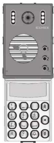
1286 1286/P
1282, 1286
The instruction manual is downloadable from the site www.vimar.com
Description
Types 1282 (1282/P) and 1286 (1286/P) correspond respectively to standard electronic units for the composition of 2 models of alphanumeric entrance panel.
1282 (1282/P) audio electronic unit with electronic agenda, keypad and graphic display.
An electronic unit similar to 1282 is also used in the Pata- vium (8844/T) and Stainless Steel Flat (8844/A, 8844/AK) series.
1286 (1286/P) video electronic unit with high-definition colour camera, electronic agenda, keypad and graphic display.
An electronic unit similar to 1286 is also used in the Patavium (8847/CT) and Stainless Steel Flat (8847/AC, 8847/ACK) series.
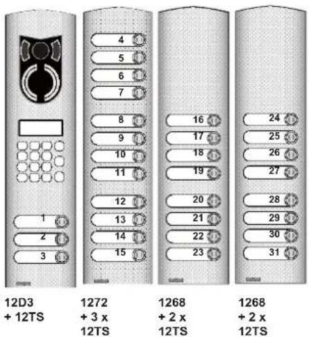
Versions 1282/P and 1286/P are equipped with wiring for connection of additional modules with conventional call push-buttons which enable direct calls to a maximum of 30-31 internal users (see Fig. 28, 29 on page 17).
All entrance panels are supplied with 122x32 pixel graphic display and an electronic agenda for up to 2000 users (comprising 16 characters). Several names can be associated with the same internal unit (number) (such as names of husband-wife).
The electronic units are to be used with 1200 series or modular 8000 series plates and components, supplied separately.
The electronic entrance panels can generate, via alphanumeric keypad, different call codes ranging from: 1 to 99999999 for 8-digit operation (default) or 1 to 9999 for 4-digit operation (by setting parameter 11 "number of digits" to 4). Panels are designed to operate either alone or together with other panels to construct a building complex type system. The technical parameters can be programmed directly via the keypad or by connecting to a computer using the "ANALYZER" software type 94CD and interface type 6952 or type 6952/A.
Entrance panel operating characteristics
- Option of adjusting the keypad backlight intensity, for optimum legibility and energy saving.
- Agenda for up to 2000 users, with option of expansion;
- Encoded lock function with 2000 code memory;
- Search names in mobile phone type agenda (select first letter of the name of the person you want to call);
- Camera LED brightness control (fade-in effect);
- Software adjustment of loudspeaker volume, microphone volume and balance via bar graph on display or via parameter;
- Parameter cross-consistency check. Since certain parameters are correlated, when they are modified a consistency check is performed and in the event of an error a warning message is generated to indicate that the correlated parameters must be adjusted.
- Option of 8 (default) or 4-digit operation.
- Possibility of assembling a composite entrance panel by adding up to 31 individual keys via additional modules type 12TS, 12TD (e.g. direct call to switchboard, or to offices);
- PRE DIGIT function, e.g. facility to store a variable pre-code of between 1 and 4 digits. This function is particularly useful for stairway entrance panels in residential complexes;
- Date and time display in the main menu;
- 6 selectable languages for the user guide;
- Time band memory (store up to two daily time bands for each day of the week) for encoded door lock control.
ELECTRONIC UNIT
The electronic unit is equipped with a speech unit, camera (on video versions), backlit graphic display, a keypad and wiring for terminal block connections. The 1282/P and 1286/P versions are also equipped with wiring for connection of additional push-button modules. The electronic unit occupies the space of two modules arranged vertically.
The electrical specifications are:
Supply voltage: 12V +/- 15% Absorbed current (with supply voltage of 13.5V)
| In standby, with low LED brightness (para. 25 = default) 106mA | |
| At start-up, keypad LED intensity high (para. 26 = default) | 132mA |
| At full power (answering call with camera and audio on) | 260mA |
The colour video versions are supplied with a 480 TV line high-resolution camera, with the following specifications:
- 1/4" CCD sensor"
- aspheric lens f=2.7mm, F=2.3
- subject lighting less than 1.0 lux.
All cameras have a manual pan and tilt facility. This adjustment can be performed after removing the outer plate of the entrance panel.
Example of standard electronic unit with camera.
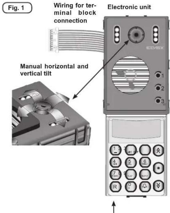
The bottom of the electronic unit, indicated by the arrow in the picture, is fitted with jumper J1 for current generator on/off activation (ON = jumper activated, OFF = jumper deactivated). If the generator is activated, the factory-preset nominal output current is 25mA.
NOTE: The pack contains a rubber gasket for fitting around the loudspeaker grill, which must be applied to the front of the electronic unit, only when installing 8000 series entrance panels.
TERMINAL BLOCK

Terminal Description
+1 Monitor shutdown control terminal.
S Electric lock activation control terminal.
F2 Auxiliary function 2 activation control terminal.
F1 Auxiliary function 1 activation control terminal.
+L Panel active terminal.
CH Call signal activation control terminal.
8 Terminal for voice signal in building complex.
6 Terminal for digital signal in building complex.
V2 Video signal terminal.
M Video signal earth terminal.
V1 Video signal input terminal.
5 +13.5Vdc supply voltage terminal.
4 Negative supply voltage terminal.
3 Terminal for voice signal to interphone/monitor cable riser.
1 Terminal for digital signal to interphone/monitor cable riser.
V Video signal output terminal.
M Video signal earth terminal.
VL Key lighting LED power supply terminal for additional modules.
PRELIMINARY OPERATIONS
(only for versions 1282/P and 1286/P)
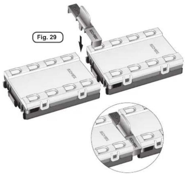
Electronic units type 1282/P and type 1286/P can be connected to individual push-button modules to provide up to a maximum of 31 push-buttons using the additional modules with push-buttons in single row, or up to 30 push-buttons using an additional module with push-buttons in double row.
For expansion with call push-buttons it is necessary to connect additional modules (type 12TS or 12TD): 12TS for push-buttons in single row or type 12TD for push-buttons in double row.
Fig. 28
Type 1282/P, type 1286/P

flowchart
graph TD
    A["ECV6X Device"] --> B["Back"]
    B --> C["Internal Components"]
    C --> D["External Connection"]
    style A fill:#f9f,stroke:#333
    style B fill:#ccf,stroke:#333
    style C fill:#cfc,stroke:#333
    style D fill:#fcc,stroke:#333
PROGRAMMING THE HARDWARE OF ADDITIONAL PUSH-BUTTON MODULES
(make changes with system switched off)
If additional modules have been connected to the entrance panel, they must be programmed.
The additional modules are programmed using the DIP switches located under the push-button cover.

Programming assigns a unique hardware number to each push-button. On 12TS series modules, with push-buttons in single rows, there are 6 DIP switches, while on 12TD series modules, with push-buttons in double rows, there are 5 DIP switches. The DIP switches modify the hardware code of the first push-button at the top right of the module. The other push-buttons are numbered consecutively from top to bottom, right to left. It is important not to overlap the codes of push-buttons on the same panel.
The codes associated with push-buttons of additional modules are indicated below in Table 1 and Table 2.
TABLE 1 – PUSH-BUTTONS IN SINGLE ROW
Par. 06 "Buttons in 2 rows" = 0 (default)
| [1 ... 3] | [4 ... 7] |
| 4 8 16 ON 32 64 128 | 4 8 16 ON 32 64 128 |
| [8 ... 11] | [12 ... 15] |
| 4 8 16 ON 32 64 128 | 4 8 16 ON 32 64 128 |
| [16 ... 19] | [20 ... 23] |
| 4 8 16 ON 32 64 128 | 4 8 16 ON 32 64 128 |
| [24 ... 27] | [28 ... 31] |
| 4 8 16 ON 32 64 128 | 4 8 16 ON 32 64 128 |
TABLE 2 - PUSH-BUTTONS IN DOUBLE ROW
Par. 06 "Buttons in 2 rows" = 1
| [1 ... 6] | [7 ... 14] |
| 8 16 ON 32 64 128 | 8 16 ON 32 64 128 |
| [15 ... 22] | [23 ... 30] |
| 8 16 ON 32 64 128 | 8 16 ON 32 64 128 |
Fig. 31 Examples of configuration of entrance panels with additional direct call push-buttons:



PROCEDURE FOR ACCESSING ENTRANCE PANEL FUNCTIONS
Simultaneously press two or more buttons to access the entrance panel submenus listed in the following table: (the simultaneous pressing of the buttons is indicated by the symbol "+", for example R+1 indicates the simultaneous pressing of buttons R and 1).
| BUTTONCOMBINATION | PAS-SWORD | MENU ACTION | |
| Programmed in keys | INSERT KEY | If configured by par.10 "Key 0-R1-C" enables the keycode to be inserted | |
| Programmed in par. 45 "F1 code" | INSERT F1 CODE | Activates function F1 | |
| Programmed in par. 46 "F2 code" | INSERT F2 CODE | Activates function F2 | |
| 123 (default) | PROGRAMMING | Enables access to the entrance panel setup menu | |
| 123 (default) | VOLUME CONTROL | Accesses the menu for volume control with call in progress | |
| 1234 | MEASURE-MENTS | Displays the measurements taken by the entrance panel on the bus | |
| 222 (default) | AGENDA SETUP | Enables access to the agenda programming menu. | |
| None | DATALOGGER | Enabled by parameter 30, accesses the datalogger menu | |
| None | SOFTWARE VERSION | Displays the software version of the entrance panel |
QUICK FUNCTION BUTTONS
When the entrance panel is displaying the main menu, certain buttons are used to access quick functions. The functions are listed below in order of priority.
| Button | Setup parameter Function | |
| “” | Par. 47 1st quick number Calls the stored number | |
| (if users are present in the agenda) | Access user agenda | |
| “” | Par. 19 Enable switchboard call = 2 | Send call to main switchboard |
| Par. 48 2nd quick number Calls the stored number | ||
| (if users are present in the agenda) | Access user agenda | |
| “*” | (if users are present in the agenda) | Access user agenda in search mode |
| “0” | INSERT KEY If configured by par.10 “Key 0-R1-C” enables the keycode to be inserted | |
| “△” | INSERT KEY If configured by par.10 “Key 0-R1-C” enables the keycode to be inserted | |
THE PANEL SETUP MENUS
To access the entrance panel setup menus, simultaneously press push-buttons R + 4 and enter the technical programming password (parameter 8), the default value is 123.
The entrance panel initially displays the firmware version then after 10 seconds or when a button is pressed it enters the setup menu.
The various submenu items can be scrolled using the "√" and "×" buttons. The selectable submenu is indicated by the "arrow. The selectable submenus are:
| Submenu | |
| PARAMETERS This menu provides access to the entrance panel operating parameters | |
| KEYCODES This menu is used to program the keys insert table from keypad | |
| HW - SW ASSOC. From this menu, which is only visible if the SW encoding parameter (par. 07) is different from 0, and therefore if HW – SW association is enabled, it is possible to associate the hardware code of direct call push-buttons (optional) with a software number which will be used to make the call. | |
| TIME BANDS Time bands are programmed from this menu | |
| STORE TRANSPONDER | Transponder keys are programmed from this menu. |
| DEL.TRANSPON-DER | From this menu it is possible to delete tran-sponder keys which have already been inserted individually. |
| ERASE KEYS From this menu it is possible to completely erase the key database, from keypad or from transpon-der.To delete the keys it is necessary to enter code 321. | |
PROGRAMMING ENTRANCE PANEL TECHNICAL PARAMETERS
The entrance panel is delivered with the technical parameters initialised with the default value. If the value of one or more parameters needs to be modified, it is possible to:
- Access the entrance panel parameters from the "PARAMETERS" menu on the entrance panel;
- Use a computer and the "ANALYZER" software type 94CD to connect to the entrance panel with interface type 6952 or 6952/A
ACCESSING THE ENTRANCE PANEL PARAMETER MENU
To access the entrance panel setup menus, simultaneously press push-buttons R + 4 and enter the technical programming password (parameter 8). The default value is 123.
The entrance panel initially displays the firmware version then after 10 seconds or when a button is pressed it enters the setup menu.
The various submenu items can be scrolled using the "☐" and "☐" buttons. The selectable submenu is indicated by the "arrow."
Select the "PARAMETERS" item and press
After programming has been completed, connect the entrance panel to the system by connecting the digital signal wire to connector terminal 1.
PROGRAMMING WITH "ANALYZER"
For programming with the "ANALYZER" software, refer to the instructions supplied with the product.
With the entrance panel switched off, connect interface type 6952 or 6952/A to terminals 14 of the connector on the entrance panel. If multiple entrance panels are connected in parallel, the entrance panel can be programmed while still connected to the system if a code has been assigned to the entrance panel ("entrance panel code" parameter) and by setting the same value in the Analyzer Digibus address. Otherwise, if using Digibus address = 0, the entrance panel must be isolated from the rest of the system by disconnecting the digital signal wire which goes from terminal 1 to the interphone riser and to the other entrance panels.
ENTRANCE PANEL PARAMETERS
The entrance parameters are listed in the following table:
| N Parameter Min. Default Max Notes | |||||
| 01 Init.User 1 1 99999999 Lowest number of users called from the entrance panel | |||||
| 02 Final User 1 99999999 Highest number of users called from the entrance panel | |||||
| 03 | Panel Number | 0 | 0 | 99999999 | ID number of the entrance panel for calls from switchboard. We advise you to always use numbers above 99000000 |
| 04 Pre-code 0 0 9999 Number assigned to the number entered from the keypad | |||||
| 05 Sum number 0 0 99999999 (Only for .../P versions) | If parameter 07 = 0, the value programmed for this parameter is added to the hardware code of the pressed button to obtain the number of the internal user called.E.g. Para. 05 = 10, button pressed = 8 -> the panel calls internal user 18. | ||||
| 06 Buttons in 2 rows 0 0 1 (Only for .../P versions) | 1 = The push-buttons of the entrance panel and those of the additional modules are arranged in two parallel rows;0 = The push-buttons of the entrance panel and those of the additional modules are arranged in a single row | ||||
| 07 SW encoding 0 0 2 (Only for .../P versions) | The HW-SW association of the direct call push-buttons can only be programmed when the parameter is enabled:0 = HW -SW association disabled.1 = HW -SW association enabled. If number NNN is associated with push-button X, when X is pressed the panel calls number NNN. If however 0 is associated with push-button X, when X is pressed the panel does NOT send the call.2 = HW -SW association enabled. If number NNN is associated with push-button X, when X is pressed the panel calls number NNN. If however 0 is associated with push-button X, when X is pressed the panel calls number X. | ||||
| 08 Tech.Prg Key 1 123 9999 Key for accessing the entrance panel setup menus. | |||||
| 09 Agenda Key 1 222 9999 Key for accessing the user agenda management menus | |||||
| 10 | Key 0-R1-C | 0 | 1 | 2 | Procedure for inserting the key for the door lock release:0 = press '0' to enable the key to be entered1 = press R and 1 to enter the key2 = press " [IMAGE]" to enter the key |
| 11 | Digit number | 4 | 8 | 8 | Number of digits used in digibus communication.The only possible options are 4 or 8. |
| 12 | Select Language | 0 | 0 | 8 | Parameter for selecting the message display language0 = Italian1 = English2 = Spanish3 = French4 = German5 = Portuguese6 = Swedish7 = Polish8 = Slovenian |
| 13 | Panel Block | 0 | 0 | 1 | 1 = the panel is blocked and does not make calls |
| 14 | Enab. Priority | 0 | 0 | 1 | 1 = the entrance panel has priority over other panels connected in parallel. If there is a call in progress from the other panels, it is possible to make a call by disconnecting the line to the other panels. |
| 15 | Enab.Lock | 0 | 1 | 6 | Configures the door lock opening modes. See "DESCRIPTION OF FUNCTIONS AND PARAMETERS - Lock activation mode" (page 24) |
| 16 | Enab.Camera | 0 | 1 | 1 | 0 = the video camera is not enabled, therefore the entrance panel only makes audio calls;1 = the video camera is enabled and the entrance panel makes audio / video calls |
| 17 | Enab.Panel Tone | 0 | 1 | 1 | 0 = acoustic signals are disabled1 = acoustic signals are enabled |
| 18 | Enab.Self-start | 0 | 0 | 255 | 0 = self-start disabled, otherwise self-start is enabled according as described in "DESCRIPTION OF FUNCTIONS AND PARAMETERS - Enable self-start". |
| 19 Enab.Switchboard. Call | 0 0 3 Enables the call to switchboard function. Used when the entrance panel is a secondary panel in a building complex:0 = Switchboard call disabled1 = Switchboard call from direct call push-button programmed in Par. 202 = Switchboard call from " [IMAGE]" button3 = Switchboard call from direct call push-button and from " [IMAGE]" button | ||||
| N Parameter Min. Default Max Notes | |||||
| 20 Switchbd button 0 0 255 If the entrance panel is a secondary panel and parameter 19 = 1, when the direct call button with the same hardware code as the code programmed in this parameter is pressed, the entrance panel substitutes the called number with the entrance panel number (parameter 3) and sends the call on the serial line to the main panel / main switchboard. | |||||
| 21 | Audio Active | 0 | 1 | 1 | 1 = The entrance panel activates automatically when the audio line is charged and the audio voltage is less than 7V0 = the entrance panel does not activate |
| 22 Pre-code digits 1 4 4 Number of digits used for the pre-code (par. 04) | |||||
| 23 | Conv.Duration | 0 | 120 | 1800 | Conversation duration in seconds. When the set time has elapsed the entrance panel terminates the call. |
| 24 Tone Duration 0 1 255 Interphone ringtone duration in seconds (CH line activation). | |||||
| 25 | Answer time | 1 | 30 | 1800 | Time in seconds waiting for answer from the receiving interphone. When the time elapses the panel terminates the call |
| 26 | Funct.1 Time | 1 | 1 | 255 | F1 function (F1 line) activation duration in secondsCheck that the set times are compatible with the devices connected to the corresponding outputs of the power supply. |
| 27 | Funct.2 Time | 1 | 1 | 255 | F2 function (F2 line) activation duration in secondsCheck that the set times are compatible with the devices connected to the corresponding outputs of the power supply. |
| 28 Lock time 1 1 255 Lock (SR line) activation duration in secondsCheck that the set times are compatible with the devices connected to the corresponding outputs of the power supply. | |||||
| 29 | Enab.Up Window | 0 | 1 | 1 | Enables the "initial user" - "final user" filter also for commands transferred from terminal 1 to terminal 6 of the entrance panel (0=No, 1=Yes). |
| 30 | Datalogger (R9) | 0 | 0 | 1 | 1 = Activates the panel datalogger.The datalogger records the transfer of messages over the digibus line. To access the datalogger press R + 9 |
| 31 View debug 0 0 1 | 1 = activates debug messages displayed from the entrance panel. | ||||
| 32 | Min LCD Lux (%) | 0 | 5 | 100 | Brightness of the LCD / keypad backlight LEDs and additional mo- dules with the entrance panel in standby |
| 33 | Max LCD Lux (%) | 0 | 50 | 100 | Brightness of the LCD / keypad backlight LEDs and additional mo- dules when the entrance panel is active |
| 34 | TLC Lux (%) | 0 | 25 | 100 | Brightness of the camera lighting LEDs |
| 35 Seconds [0,59] (entrance panel in - ternal clock) | 0 0 59 | Seconds setting of the entrance panel internal clock. | |||
| 36 Minutes [0,59] (entrance panel inter- nal clock) | 0 0 59 | Minutes setting of the entrance panel internal clock. | |||
| 37 Hours [0,23] (entrance panel internal clock) | 0 0 23 | Hours setting of the entrance panel internal clock. | |||
| 38 Days of the month (entrance panel internal clock) | 1 1 31 | Day of the month setting of the entrance panel internal calendar. | |||
| 39 Month [1,12] (entrance panel internal clock) | 1 1 12 | Month setting of the entrance panel internal calendar. | |||
| 40 | Year (internal clock entrance panel) | 2008 | 2008 | 2099 | Year setting of the entrance panel internal calendar. |
| 41 Day setting [0,6] (internal clock en - trance panel) | 0 0 6 Day of the week setting of the entrance panel internal calendar.0 = Sunday | ||||
| 42 | External volume | 0 | 30 | 63 | Volume of the entrance panel loudspeaker signal. See paragraph he- aded "ENTRANCE PANEL VOLUME ADJUSTMENT" |
| 43 | Internal volume | 0 | 30 | 63 | Volume of the entrance panel microphone signal See paragraph he- aded "ENTRANCE PANEL VOLUME ADJUSTMENT" |
| 44 | Balance | 0 | 21 | 63 | Balance of the telephone fork circuit See paragraph headed "EN- TRANCE PANEL VOLUME ADJUSTMENT" |
| 45 | F1 Code | 0 | 0 | 99999999 | Code for activation of function F1 |
| 46 | F2 Code | 0 | 0 | 99999999 | Code for activation of function F2 |
| 47 1 | Memory Num. 0 0 99999999 | Quick call number associated with the button " [IMAGE].0 = disabled | |||
| 48 2 | Memory Num. 0 0 99999999 | Quick call number associated with the button " [IMAGE].0 = disabled | |||
| 49 Ext.1 Address 0 0 99999999 Address of external transponder reading device 1 | |||||
| 50 Ext.2 Address 0 0 99999999 Address of external transponder reading device 2 | |||||
| 51 Ext.3 Address 0 0 99999999 Address of external transponder reading device 3 | |||||
| 52 Ext.4 Address 0 0 99999999 Address of external transponder reading device 4 | |||||
| 53 Ext.5 Address 0 0 99999999 Address of external transponder reading device 5 | |||||
| 54 Ext.6 Address 0 0 99999999 Address of external transponder reading device 6 | |||||
| 55 Ext.7 Address 0 0 99999999 Address of external transponder reading device 7 | |||||
| 56 Ext.8 Address 0 0 99999999 Address of external transponder reading device 8 | |||||
| 57 | Tx Key | 0 | 0 | 3 | 0 = does not transmit the key;1 = transmits the key if it is in the entrance panel database2 = transmits the key if it is not in the entrance panel database3 = always transmits the key |
| 58 | Request Passw | 0 | 0 | 1 | 1 = requests password confirmation from the transponder reading device |
| 59 | Tx UP / Down | 0 | 1 | 1 | 0 = transmits the key on interphone cable riser serial line (UP)1 = transmits the key to the main entrance panel / switchboard (DOWN) |
| 60 | Hidden Paras | 0 | 0 | 50 | Typing 27 enables the display and programming of parameters 61 - 67 |
| 61 | Mon. Off Time | 0 | 30 | 1000 | Monitor power-off timeout.The programmed value is multiplied by 10ms, therefore if Mon. Off Time = 30 then the timeout = 300ms |
| 62 | Transit Time | 0 | 5 | 1000 | Maximum transit time in minutes |
| 63 | Command Rep.(+) | 0 | 388 | 65535 | Repetition of special commands |
| 64 Restart Time(h) 0 0 99999999 NOT USED | |||||
| 65 | Factory reset. | 0 | 0 | 99999999 | Typing the code 31830988 resets the parameters to their default values. |
| 66 | Flash sector reset | 0 | 0 | 26 | Erases the flash sector indicated from 1 to 26.IMPORTANT! Improper use of this parameter can damage the entrance panel or cause malfunctions! |
| 67 | Number of keys from keypad | 0 | 100 | 2000 | Maximum number of keys insertable from keypadIf the parameter is 0, the keys from keypad are disabled. |
DESCRIPTION OF FUNCTIONS AND PARAMETERS
Initial User (1) and Final User (2). These parameters must be programmed in the case of a building complex type system and indicate the range of users served by the entrance panel. The two values must only be set in stairway (secondary) entrance panels. If the entrance panel receives a call from the main entrance panel or from a switchboard for a user in the initial user – final user range, it forwards the call and enters engaged status, otherwise it doesn't forward the call and remains free. When the entrance panel is in engaged status no operation can be performed, however if the panel is free it can be used to call served users.
Connection of entrance panels in parallel in building-complex systems:
When there are multiple stairway entrance panels connected in parallel, only one has to convey commands from the stairway entrance panel to the interphone riser. The user window of the entrance panel that conveys the commands will be "open" and therefore:
initial user = number of first user served
final user = number of last user served
The user windows of the other panels will be closed and therefore:
initial user = final user = entrance panel number
In the borderline case of a single user served by multiple entrance panels in parallel, one panel will have:
initial user = final user = internal number,
the others will have:
initial user = final user = entrance panel number
Entrance panel code "Panel Number" (3).
This is the ID code of the entrance panel in the system, equal to the number assigned to the interphone. It must be programmed:
- On building-complex systems with switchboard, to enable the entrance panel to call the switchboard;
2- When there are multiple entrance panels connected in parallel, to ensure the unambiguous identification of the entrance panels it is advisable to use numbers such as "99xxxxxx", or in any event numbers that are higher than those used for internal units.
NOTE: In all cases the number of the entrance panel must be unique and different from the interphone and monitor call codes.
Pre-code (4) and number of pre-code digits (22).
These two parameters are used to set up a quick call system for calling users served by the entrance panel. When the pre-code is different from 0, the entrance panel automatically places the pre-code before the entered number to form the number to call. The pre-code consists of the digits programmed in the "number of pre-code digits" parameter counted from the left of the complete number. For example, if the complete number consists of 8 digits; number of pre-code digits = 4; pre-code = 91, and number entered = 15. Then we have:
| pre-code digits = 4; p = pre-code; n = number entered | p | p | p | n | n | n | |||
| Position occupied by the digits in the dialled number | 9 | 1 | 1 | 5 | |||||
| Number called 9 1 0 0 1 5 |
The number called by the entrance panel will be 910015.
If the conditions are the same as those listed above but with the number of pre-code digits = 3 then the dialled number becomes:
| pre-code digits = 4; p = pre-code; n = number entered | p | p | p | n | n | n | n | n | |||
| Position occupied by the digits in the dialled number | 9 | 1 | 1 | 5 | |||||||
| Number called 9 1 0 0 0 1 5 |
The number called by the entrance panel becomes 9100015.
Shift code "Sum Number" (5). (For /P version entrance panels) This is a constant number which is added to the button hardware value, enabling the value of all buttons to be shifted automatically. In fact, when this parameter is different from 0, the entrance panel sends the call using the sum number + hardware number as the code. This function is disabled if Para.07 (SW encoding) is active, giving priority to the HW-SW association.
Push-buttons in double rows "Buttons in two rows" (6). (For /P version entrance panels) The parameter must be programmed depending on the layout of the push-buttons on the modules: with "0" for push-buttons in single row and "1" for push-buttons in double row. The status of this parameter changes the hardware code assigned to additional push-button modules.
Software encoding (Hardware – software association) (7). (For /P version entrance panels) The HW-SW association of the entrance panel push-buttons can only be programmed when the parameter is enabled. The possible options are:
0 = HW -SW association disabled
1 = HW -SW association enabled. If number NNN is associated with push-button X, when X is pressed the panel calls number NNN. If however 0 is associated with push-button X, when X is pressed the panel does NOT send the call
2 = HW -SW association enabled. If number NNN is associated with push-button X, when X is pressed the panel calls number NNN. If however 0 is associated with push-button X, when X is pressed the panel calls number X.
(see chapter headed "ENTRANCE PANEL HW - SW ASSOCIATION MENU")
Key for accessing the entrance panel setup menu "Tech.Prg Key" (8).
This is the password for accessing the entrance panel setup menus.
Key for accessing the agenda setup menu "Agenda key" (9). This is the password for accessing the agenda setup menus.
Method for accessing the door lock release menu with numeric key "Key 0 - R1 - C" (10). Defines the method for accessing the menu to insert the encoded key for the door lock release and the activation of functions F1 and F2, according to the programming of the individual key.
On entering the menu, the message "Insert Code" appears. At this point enter your code and press "☐"
If par.9 = 0, enter the menu by pressing the "0" button
If par.9 = 1, enter the menu by simultaneously pressing buttons "R+1"
If par.9 = 2, enter the menu by pressing the " 🔊" button
Encoding system "Digit Number" (11). Defines the type of digibus protocol used by the entrance panel to communicate with other devices in the system. The parameter must be set to 4 if the system contains devices which operate with 4 digits, otherwise the 8-digit protocol must always be used.
Language selection (12). Selects the language used by the entrance panel for the user interface. Parameter for selecting the message display language. The available languages are:
0 = Italian
1 = English
2 = Spanish
3 = French
4 = German
5 = Portuguese
6 = Swedish
"Panel Block" function (13). The main functions of the entrance panel (sending a call) can be blocked. If the parameter is set to "1", all of the entrance panel functions are disabled except for access to the programming parameters.
Enable priority (14). This function can be used when multiple entrance panels are connected in parallel. If the function is active, the entrance panel does not enter "engaged" status when one of the entrance panels connected in parallel engages the cable riser, and remains free to be able to make another call, interrupting the call in progress. If multiple entrance panels have the "enable priority" function active, the last entrance panel to make the call will always occupy the line.
This function is only effective for entrance panels interconnected in parallel; for building-complex systems, stairway entrance panels still enter engaged status if the call comes from a main entrance panel or a switchboard.
Lock activation mode "Enab. Lock" (15). This parameter configures the opening of the local door lock, e.g. the lock connected to the entrance panel SR terminal or the lock connected to the main entrance panel, according to the following procedures:
| “Enab. Lock” = Open with: | |
| 0 Conversation in progress (1) | |
| 1 Conversation in progress (1);transit (2) | |
| 2 Conversation in progress (1)Switched audio (3) | |
| 3 Modes 1 and 2 are active simultaneously | |
| 4 Conversation in progress (1)Transit (2)Interphone call (4) | |
| 6 Modes 4 and 2 are active simultaneously |
(1) The entrance panel has a conversation in progress with the interphone which sends the lock opening command;
(2) the entrance panel is conveying a call from the main entrance panel or from the switchboard to an interphone in its cable riser;
(3) the entrance panel is in conversation with a main switchboard. The lock opening command reaches the switchboard;
(4) the interphone is not in conversation and sends the switchboard call command.
Enable camera "Enab. Camera" (16).
This parameter is set by default to 0 for audio entrance panels audio or to 1 for audio / video entrance panels. Must be set to 1 for audio entrance panels with separate camera. This enables correct switch on/off management of system monitors.
Enable entrance panel tone "Enab. Panel Tone" (17).
The entrance panel emits a beep in response to certain events, such as pressing a button. This parameter can be used to disable the beeps.
Enable Self-start "Enab. Self-start" (18).
The entrance panel can self-start, e.g. activate automatically without anyone making a call, if it receives a command from an interphone.
This parameter enables and configures the entrance panel self-start mode, as shown in the following table:
| Self-start = The entrance panel activates with the command: | |
| 0 Self-start function | disabled |
| 1 | F3 |
| 2 | F4 |
| 4 | F5 |
| 8 | F1 |
| 16 F2 | |
| 32 F6 | |
| 64 F7 | |
| 128 F8 | |
Combinations of multiple commands are obtained by adding together the values indicated for the individual command, e.g.:
Self-start = 7 (4 + 2 + 1) The entrance panel activates with the F3, F4 and F5 commands;
Self-start = 96 (64 + 32) The entrance panel activates with the F6 and F7 commands;
Self-start = 129 (128 + 1) The entrance panel activates with the F3 and F8 commands;
Enable Switchboard Call "Enab.Switchboard Call" (19), Switchboard call button "Switchbd button" (20).
Parameter 19 must be set if the entrance panel is a secondary panel in a building complex system with switchboard. In this case, if Par. if 19 = 1 and the panel is equipped with additional push-buttons, when the push-button selected with the switchboard call button parameter (20) is pressed, the entrance panel sends the call with its ID code (parameter 3) to the switchboard. However if Par. 19 = 2 the switchboard call is sent by pressing the "

button. If Par 19 = 3 both modes are active.
Audio Active (21). If this parameter is equal to 1, the entrance panel activates when the audio line is charged and the audio voltage is less than 7V. In the case of multiple entrance panels connected in parallel, automatic activation of the entrance panels may cause feedback due to the Larsen effect. In this case it is advisable to activate the function on only one of the entrance panels.
Conversation Duration "Conv. Duration" (23). This is the maximum duration of the conversation in seconds. The conversation time begins from the moment that the handset is lifted after the interphone has received the call. Once this time has elapsed, the entrance panel terminates the call and returns to free status.
Ringtone duration "Tone duration" (24). This parameter represents the time, in seconds, for which the entrance panel activates the CH terminal. If the entrance panel CH terminal is connected to the CH terminal present on power supply units type 6941 and 6948, the call generator activates which sends the ringtone to the interphone.
If the system has stairway entrance panels (building complex) or a switchboard, the main entrance panel call signal activation time must be 1 second longer than the corresponding time set on the stairway entrance panels or on the switchboard. In other cases the parameter can be modified at the discretion of the installer. In interphones in which the ringtone is generated by the interphone itself, such as type 6600 or 7200, the duration of the tone is independent of the parameter set on the entrance panel.
Answer time (25). This is the maximum time, expressed in seconds, within which the receiving internal user's handset must be raised from the moment that the entrance panel has sent the call. If the answer does not arrive within the programmed time, the entrance panel terminates the call and returns to free status.
F1 function activation time "Funct. 1 Time" (26). This is the time, expressed in seconds, for which the entrance panel activates the F1 terminal. If the entrance panel F1 terminal is connected to the F1 terminal on power supply units type 6941 and 6948, a relay is activated which closes the contact between terminals R1 and 4. If the parameter is equal to 0, the activation time is fixed by the entrance panel to 0.5 sec.
Check that the set times are compatible with the devices connected to the corresponding outputs of the power supply.
F2 function activation time "Funct. 2" (27). This is the time, expressed in seconds, for which the entrance panel activates the F2 terminal. If the entrance panel F2 terminal is connected to the F2 terminal present on power supply units type 6941 and 6948, a relay is activated which closes the contact between terminals R2 and 4. If the parameter is equal to 0, the activation time is fixed by the entrance panel to 0.5 sec.
Check that the set times are compatible with the devices connected to the corresponding outputs of the power supply.
Lock activation time "Lock Time" (28). This is the time, in seconds, for which the entrance panel activates the SR terminal. If the entrance panel SR terminal is connected to the SR terminal present on power supply units type 6941, 6942 and 6948, the lock connected to terminals 15 and S1 is activated. If the parameter is equal to 0, the activation time is fixed by the entrance panel to 0.5 sec.
Check that the set times are compatible with the devices connected to the corresponding outputs of the power supply.
Enable UP window "Enab. UP Window" (29). If set to 1 (default value) this enables the "initial user" – "final user" filter for "down" commands, e.g. commands conveyed from the external interphone cable riser to the main entrance panel or to the switchboard. In this case, only commands with sender IDs that are inside the window range are conveyed by the entrance panel. If however the parameter is equal to 0 the filter is deactivated, therefore the entrance panel conveys all commands, including those with sender IDs that are outside the window range.
It may be necessary to use this function in the case of building-complex systems in which there are multiple entrance panels connected in parallel both on the interphone cable riser side, and therefore with terminal 1, and on the main entrance panel side, therefore with terminal 6.
1282 -1286
Activate datalogger "Datalogger (R9)" (30). If set to 1 the entrance panel datalogger is activated. The datalogger records messages generated by the entrance panel or which are transmitted over the databases connected to the entrance panel (cable riser serial line and serial line to the main entrance panel) and can be displayed by simultaneously pressing buttons R + 9. For each message the entrance panel stores the ID of the recipient, the type of command, the time it was detected, the direction of transit and the total number of stored messages. The entrance panel stores in memory the last 400 messages detected. The events are erased if the power to the entrance panel is interrupted. The datalogger is a useful tool for testing a system and identifying possible faults.
Activate debug messages "Disp. debug" (31). If set to 1 every command addressed to the entrance panel is shown on the display, indicating the type of command and the sender ID.
This is a useful tool for testing a system and identifying possible faults.
Backlight minimum brightness "Min LED Lux (%)" (32).
This is the luminous intensity, expressed as a percentage, of the backlighting LEDs of the panel keypad and LCD screen when the panel is in standby. The entrance panel reaches the minimum brightness value after approximately 10 seconds of inactivity since the last completed action.
Backlight maximum brightness "Max LED Lux (%)" (33). This is the luminous intensity, expressed as a percentage, of the backlighting LEDs of the panel keypad and LCD screen when the panel is on. The entrance panel reaches the maximum brightness value when performing functions and returns to the minimum value after approx. 10 seconds of inactivity.
Camera LED brightness "TLC Lux (%)" (34). This is the luminous intensity, expressed as a percentage, of the camera lighting LEDs. (Only for entrance panels connected to cameras).
Seconds, Minutes, Hours, Day of the month, Month, Year, Day of the week. (35) – (41). These parameters configure the entrance panel clock – calendar.
External volume (42) Internal volume (43) Balance (44). The entrance panel is equipped with digital trimmers for adjusting the audio volume and balance. These parameters directly control the trimmers and can be modified by directly typing the new parameter value or by adjusting the volume while making a call.
F1 Code (45). This parameter is for programming the code to activate function F1 from keypad. To enter the code simultaneously press buttons + 2.
F2 Code (46). This parameter is for programming the code to activate function F2 from keypad. To enter the code simultaneously press buttons + 3.
First number in memory "1 Num. Memory" (47).
This parameter is for programming the quick call number associated with the “☐” button. If the number is 0, the function is disabled.
Second number in memory "2 Num. Memory" (48).
This parameter is for programming the quick call number associated with the "☐" button. If the number is 0, the function is disabled.
The quick call function is secondary to the switchboard call function. If parameter 19 "Enab. Switchbd Call" is enabled, when "☐" is pressed, the call to switchboard is sent on the digibus channel to the main entrance panel / switchboard.
External reader address "Ext 1 - 8 Address" (49) - (56). Up to 8 transponder readers can be connected to the entrance panel via the interphone cable riser digibus channel, terminal 1. The ID code of the readers from which the entrance panel can receive the key must be programmed in these parameters.
Transmission of received key "Tx Key" (57). The keycode received by one of the transponder readers connected to the interphone cable riser digibus channel, can be forwarded by the entrance panel in the following ways:
| Tx Key = | Action: |
| 0 Doesn't | transmit the key |
| 1 Transmits the key if it is present in the entrance panel database | - |
| 2 Transmits the key is it is not present in the entrance panel database | |
| 3 Always | transmits the key |
Request confirmation code from transponder reader "Request Passw" (58). When the entrance panel receives a key it can request a confirmation from the transponder reader sending a message encoded with a password. If this parameter is equal to 1 then confirmation is requested, otherwise not.
Transmission of key to Up or Down serial line "Tx UP / Down" (59). If parameter 57 is different from 0, this parameter decides which channel the keycode will be forwarded on: if para. 59 = 0 the entrance panel transmits the key on the interphone cable riser digibus channel (UP) otherwise on the digibus channel to the main entrance panel / switchboard (down).
Access to hidden parameters "Hidden paras" (60). parameters from 61 to 67 are not normally accessible. These parameters must only be modified on the recommendation of Elvox technicians to prevent malfunctions or damage to the entrance panel. To access the hidden parameters, type "27" in Hidden Paras. Access to the parameters is automatically deactivated when returning to the normally accessible parameters.
Monitor power-off cycle "Mon. Off Time" (61). This parameter expresses the activation time, in tens of milliseconds, of the +I output. The entrance panel +I terminal is connected to the +I terminal present on power supply units type 6941 and 6948 and checks the power supply of the monitors to the + - terminals.
Entrance panel in transit timeout "Transit Time" (62). This is the maximum time, in minutes, for which the entrance panel remains in transit. To prevent system malfunctions from blocking the entrance panel in the engaged status, when this time has elapsed the entrance panel interrupts the communication and also frees the interphone cable riser to which it is connected.
Command repetition "Command Rep. (+)" (63). This command enables the forwarding or repetition of certain special commands, as shown in the table below: (default bit 2+7+8)
| bit | Command rep. = | Action: Default | |
| 0 None | xxx | ||
| 0 | 1 Transmits | a double reset command | 0 |
| 2 | 4 Forwards | the "NO KEY" command over the interphone cable riser digibus line | 1 |
| 3 | 8 Forwards | the "NO KEY" command over the main entrance panel digibus line | 0 |
| 4 | 16 If = 16, when the entrance panel receives the INTERCOM + TLC command it forwards the command without modifying it, otherwise it only forwards intercom without camera. | 0 | |
| 5 | 32 | If = 32: if the entrance panel receives an "S" command from the serial line on the INTERPHONE CABLE RISER side addressed to another device, it forwards it over the MAIN ENTRANCE PANEL serial line. | 0 |
| 6 | 64 | If = 64: if the entrance panel receives an "S" command from the serial line on the MAIN ENTRANCE PANEL side addressed to another device, it forwards it over the INTERPHONE CABLE RISER serial line. | 0 |
| 7 128 | Forwards the F1 command on the main panel serial line. | 1 | |
| 8 256 | Forwards the F2 command on the main panel serial line. | 1 | |
| 9 512 | The RESET command from the main entrance panel is forwarded to the interphone cable riser even if the initial user - final user window is closed. | 0 | |
1282 -1286
Caution: If the entrance panel is connected in parallel to other entrance panels with both serials (terminals 1 and 6) it is possible to enable bits 5 and 6 only on one entrance panel, whereas the others must be left disabled.
A combination of actions is obtained by adding together the values of the individual action, for example:
If Transit Time = 5 The action executed is: Transmits a double reset command and forwards the "NO KEY" command over the interphone cable riser digibus line.
Default data reset "Factory reset" (65). Setting this parameter to code 31830988 resets all the parameters to their default value.
Erase flash sector "Eras.Flash.SECT." (66). Erases the program memory sector of the specified microcontroller.
IMPORTANT! Improper use of this parameter can damage the entrance panel or cause malfunctions!
Number of keys from keypad (67). Indicates the maximum of software keys which can be inserted from keypad. The maximum number of keys (from keypad and transponder) is 2000. These keys can be divided between keypad and transponder, such that if for example par. 67 = 100, 1900 transponders can be used.
ENTRANCE PANEL VOLUME ADJUSTMENT
The entrance panel volume levels can be adjusted by modifying parameters 42, 43, 44 or via the "adjust volumes" menu when a call is in progress. It is possible to adjust:
- external volume. This is the volume of the entrance panel loudspeaker.
- internal volume. This is the volume of the entrance panel microphone signal and therefore of the system audio line.
- Balance. This is the balance of the loudspeaker / microphone signal, for eliminating feedback caused by the Larsen effect.
To access the volume adjustment menu:
- Simultaneously press push-buttons R + 5 and enter the technical programming password (parameter 8). The default value is 123.
- After entering the volume adjustment menu, enter the number of the internal user to call and press the "A" button.
Once the call is in progress:
- To change the volume level use the "☐" and "☐" buttons. The level of the selected parameter is indicated by the bar graph displayed on-screen;
- To change the parameter press the “*” button
- To save the new settings press the " 🔊" button.
Repeat the last three steps until the desired volume level is reached.
When the volume adjustment is complete, end the conversation using the R button.
PROGRAMMING KEYCODES
Software keys are codes which, depending on the programming operation, release the door lock, activate function F1 or activate function F2.
The key is inserted by the user from the main menu according to the mode programmed in parameter 10. If the key is active, the functions programmed for that key are actuated, otherwise the entrance panel displays the message "NOT FOUND". The key can be configured using the key programming submenu. The configuration parameters are initialised with default values which are identical for all keys.
The key can be always active or it can be activated within a time band. The key can also be deactivated without removing it from the list by means of bit 1 from the "OPTIONS" submenu
To access the "KEYCODES" menu, simultaneously press push-buttons R + 4 and enter the technical programming password (parameter 8). The default value is 123.
The entrance panel initially displays the firmware version then after 10 seconds or when a button is pressed it enters the setup menu.
The various submenu items can be scrolled using the "☐" and "☐" buttons. The selectable submenu is indicated by the "arrow."
Select the item "KEYCODES" and press "☐".
To program a key:
- Scroll the list of keys using the “☑” and “☒” buttons until you find a free key (keycode = 0);
- After identifying a free key, enter the desired code and press " (A)" to save.
The key is memorised with the optional parameters set to the default values.
To modify a key:
- Scroll the list of keys until you find the right one;
- Modify the value and press " Ⓞ" to save. Entering 0 deletes the key. The key is memorised with the optional parameters set to the default values.
To modify the entrance panel optional data:
- Scroll the list of keys using the “√” and “^” buttons until you find the desired key and press “*”.
The key submenus are:
- OPTIONS. Enables the key options to be modified. The available options are listed in the following table:
| bit def option |
| 1 1 Key active. The key can be deactivated by setting this bit to 0 |
| 2 1 Key continuous. The key is active 24/7. if this bit is set to 0, the key is active within the programmed time band. |
| 3 0 NOT USED |
| 4 0 NOT USED |
| 5 1 Entering the key activates the door lock |
| 6 0 Entering the key activates F1 |
| 7 0 Entering the key activates F2 |
| 8 0 NOT USED |
the option is active when the box associated with the bit is solid.
To modify an optional bit, select the bit using the "☐" and "☐" buttons. The selected bit is indicated by the "☐" arrow.
Pressing “*” changes the status of the bit.
Pressing “山区” passes to the next submenu. To save the new setting press “山区”, then scroll all the submenus until the next key is reached.
1282 -1286
• TIME BANDS. Each key can be associated with 2 time bands from a total of 16 available, which can be programmed from the time band menu.
To modify the time band select it using the "√" and "×" buttons. The selected time band is indicated by the "→arrow. Enter the new value, for values from 1 to 9 enter the digit preceded by "0" for example for time band 5, enter 05 or 5 and press the "√" or "×" button to pass to the next time band.
Pressing "☐" passes to the next submenu. To save the new setting press "☐", then scroll all the submenus until the next key is reached.
- SELECT READER. Not used
- USER DATA. Not used
- INTERNAL NUMBER. This is the number of the internal user associated with the key. It is useful when, using the "data organizer" program, you want to trace the holders of the key from the key database
If you modify one of the submenus, to save the new programmed data press "☐" and scroll all the submenus until the next key is reached.
ERASING ALL KEYCODES
To access the "ERASE KEYS" menu, simultaneously press push-buttons R + 4 and enter the technical programming password (parameter 8). The default value is 123.
The entrance panel initially displays the firmware version then after 10 seconds or when a button is pressed it enters the setup menu.
The various submenu items can be scrolled using the "☒" and "☒" buttons. The selectable submenu is indicated by the "arrow." Select the item "ERASE KEYS" and press.
The following message appears:
"ERASE KEYS"
Press a button
The following message appears:
1) Keys from keypad. 2) TRANSPONDER
Press 1 or 2
Selecting 1 deletes all of the keys insertable from keypad, selecting 2 erases all TRANSPONDER keys.
After making the selection, the following message appears:
"confirmation code"
The entrance panel prompts for the confirmation code before erasing the agenda.
Enter code 321 and press

If the procedure is successful the message "DELETED" appears
The entrance panel returns to the previous menu
HARDWARE – SOFTWARE ASSOCIATION
(Only for version 1282/P and 1286/P)
Each push-button of the entrance panel is associated with a hardware number (generated by the circuit board) from 1 to 31 (maximum number of push-buttons that can be connected to the entrance panel). If the entrance panel is required to serve users with a higher numbering range, for example from 1000 to 1020, or to call a particular user from a push-button, e.g. calling the switchboard from the main entrance panel by pressing the first push-button, or calling the same internal user from two push-buttons etc; each hardware code can be associated with a software number which the entrance panel will use to send the call.
Push-button HW-SW associations can only be programmed if parameter 07 is different from 0.
To program the associations use the "HW - SW ASSOCIATION" menu on the entrance panel, or programmer 950B.
ENTRANCE PANEL HW - SW ASSOCIATION MENU
To access the "HW - SW ASSOCIATION" menu, simultaneously press push-buttons R + 4 and enter the technical programming password (parameter 8). The default value is 123.
The entrance panel initially displays the firmware version then after 10 seconds or when a button is pressed it enters the setup menu.
The various submenu items can be scrolled using the "☐" and "☐" buttons. The selectable submenu is indicated by the "→arrow."
Select the item "HW - SW ASSOC." and press "A"
- Scroll the list of associations using the “☒” and “☒” buttons. The entrance panel does not display the codes of all push-buttons but only the first 6. The list of displayed push-buttons is lengthened each time by 6 additional elements behind the last programmed element.
- Find the hardware number of the push-button that you want to program, enter the associated software code and press " ",
- If you wish to delete and association, after identifying he push-button enter the code 0 and press "A".
PROGRAMMING WITH 950B
- Scroll the menus using the “√” and “▲” buttons on the programmer until the “ASSOC. BUTTONS” menu is selected and press the OK button.
- The entrance panel emits a confirmation tone and the message "PRESS BUTTON to CHANGE" appears on the programmer display
- Press the call push-button to which you want to associate the software number. The following message appears on the programmer display: SW. NUM=xxx" and below it "SW.N=yyyyMMddyyyy"
- Enter the software number that you want to associate and press the OK button on the programmer.
OPERATING MODES
The entrance panel has three operating modes linked to Par.07 (SW encoding):
A. If SW encoding = 0 the entrance panel activates all push-buttons, sending the call with the hardware number associated with the push-button;
B. If SW encoding = 1 the entrance panel only activates push-buttons which have an associated software number different from 0. For example if the software number of P1 is 0, the number of P2 is 5 and the number of P3 is 10, the entrance panel activates only P2 and P3 and sends calls with the associated software number, while nothing happens when P1 is pressed;
C. If SW encoding = 2 the entrance panel activates all push-buttons, sending the call with the software number if the associated software number is different from 0, sending the call with the hardware number if the associated software number parameter is equal to 0.
For example if Par.07 is equal to 2, programming is as follows:
| Push-but-ton | Num.HW Num.SW Action if button pressed |
| P1 1 0 Call user 1 | |
| P2 2 88000001 Call user 88000001 | |
| P3 3 4 Call user 4 | |
| P4 4 0 Call user 4 |
In this way it is only possible to modify the encoding of certain push-buttons, leaving the others unchanged.
PROGRAMMING TIME BANDS
The time bands associated with the keys are programmed from this menu. Each time band can be activated on one or more days of the week and has two time windows, valid for days programmed weekly.
TIME BANDS MENU
To access the "TIME BANDS" menu, simultaneously press push-buttons R + 4 and enter the technical programming password (parameter 8). The default value is 123.
The entrance panel initially displays the firmware version then after 10 seconds or when a button is pressed it enters the setup menu.
The various submenu items can be scrolled using the "☐" and "☐" buttons. The selectable submenu is indicated by the "☐" arrow.
Select the item "TIME BANDS" and press "☐".
PROGRAMMING THE TIME BAND
Important: To store the changes made in a submenu, press "④" to scroll all of the submenus and pass to the next key.
To program a time band:
- scroll the list using the “√” and “▲” buttons. After selecting the time band, press “▲” to pass to the “DAY OF THE WEEK” submenu.
DAY OF THE WEEK
Each bit indicates the day of the week on which the key is active. The days range from Sunday (first bit) to Saturday (last bit)
To modify the status of the bit, select the bit using the "☐" and "☐" buttons. The selected bit is indicated by the "☐" arrow.
Pressing " 🔊" changes the status of the bit.
Pressing the "💡" button passes to the "FIRST TIME WINDOW" submenu.
FIRST TIME WINDOW
The time window (format 0 - 23) has start hour and minutes and end hour and minutes.
To modify the time window, select the hour and minutes using the “√” and
" 🔊" buttons (the selected data is indicated by the "arrow") and enter the new value. The entrance panel is equipped with an algorithm to acquire the new value and pass to the next one based on the modified value. For example, if you modify the hour by entering a number greater than 2, for example 5, the value is considered valid immediately and the entrance panel passes to the next one, if however you enter 1 you may want to input 1 or 17, therefore the entrance panel waits for another digit to be entered.
In this case enter either 01 or 1 followed by the "☒" or "Â" button to pass to the next value. Pressing the "☐" button passes to the "SECOND TIME WINDOW" submenu.
SECOND TIME WINDOW
Proceed as described above for the first time window.
Pressing the “💡” button saves the changes made to the selected time band and passes to the next one.
AGENDA PROGRAMMING AND USE
Accessing the agenda management menu
The entrance panel manages an agenda which can contain up to 2000 users. To enter a new user, delete an existing user or to erase the entire agenda use the "agenda management" menu.
To access the "agenda management" menu:
simultaneously press push-buttons R and 7, the following message appears "Password":

enter the "agenda key" password (par. 09), the default setting is 222, and press " Â "

the "agenda" menu appears which has three items:
1) insert user
2) delete user
3) erase agenda
To insert a new user, press 1
To delete a user, press 2
To erase the entire agenda, press 3
Pressing the R button returns to the main menu.
Inserting a new user
From the "agenda management" menu select option 1.
The following message appears:
Enter name

At this point it is possible to insert the name using the entrance panel keypad

pressing the "A" button stores the name; the number of the internal user can be inserted via the entrance panel keypad

pressing the " 🔊" button completes the procedure. If the new user is stored the message "DONE" appears, otherwise if the user is present in the agenda, the message "Record already present" appears.
To select the desired character, press the corresponding button several times according to the table below.
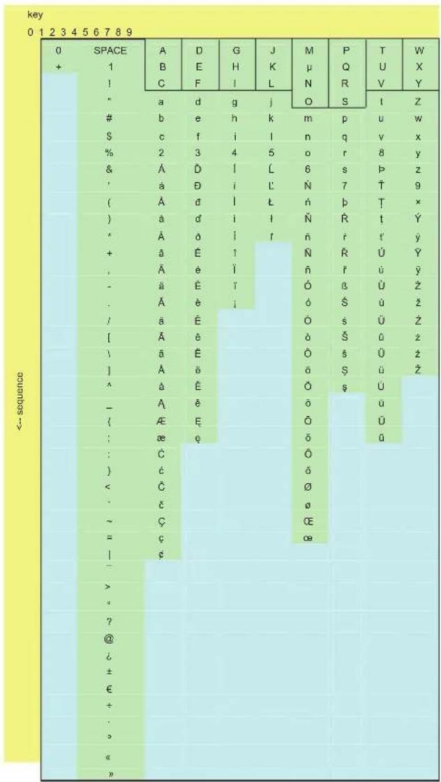
After selecting the desired character, wait for a moment for the cursor to move forward before entering the next character.
If an error occurs, the entered characters or numbers can be deleted by pressing "☐".
Pressing the R button exits the insert user mode and returns to the "agenda management" menu.
Deleting an inserted user
From the "agenda management" menu select option 2.


The user to be deleted is highlighted by the "" symbol



If the procedure is successful the message "DELETED" appears
At the end of the procedure the entrance panel remains in "delete user" mode, therefore more users can be deleted if required.
Pressing the R button returns to the "agenda management" menu.
Erasing the agenda
CAUTION: The following procedure deletes all users present in the agenda!
From the "agenda management" menu, select option 3. The following message appears:
"ERASE AGENDA"
Press a button

Pressing any button displays the following message:
"confirmation code"
The entrance panel prompts for the confirmation code before erasing the agenda.
Enter the code 123

Pressing the “ 🔊” button erases the entire agenda
If the procedure is successful the message "DELETED" appears and the entrance panel returns to the "agenda management" menu.
If you wish to exit the "erase agenda" menu without erasing the agenda, press the R button several times until you return to the main menu.
Using the agenda
If users have been stored in the agenda, they can be accessed by pressing the "💡" button or the "💡" and "💡" buttons if they have not been assigned to another function. Pressing the "💡" button accesses the agenda search menu. It is possible to find a user by scrolling the list with the and buttons or by entering the first letters of the user's name and scrolling the list of names found using the "💡" and "💡" buttons.
The selected user is highlighted by the flashing " 🔊" symbol.
Press the "☐" button to call the selected user.
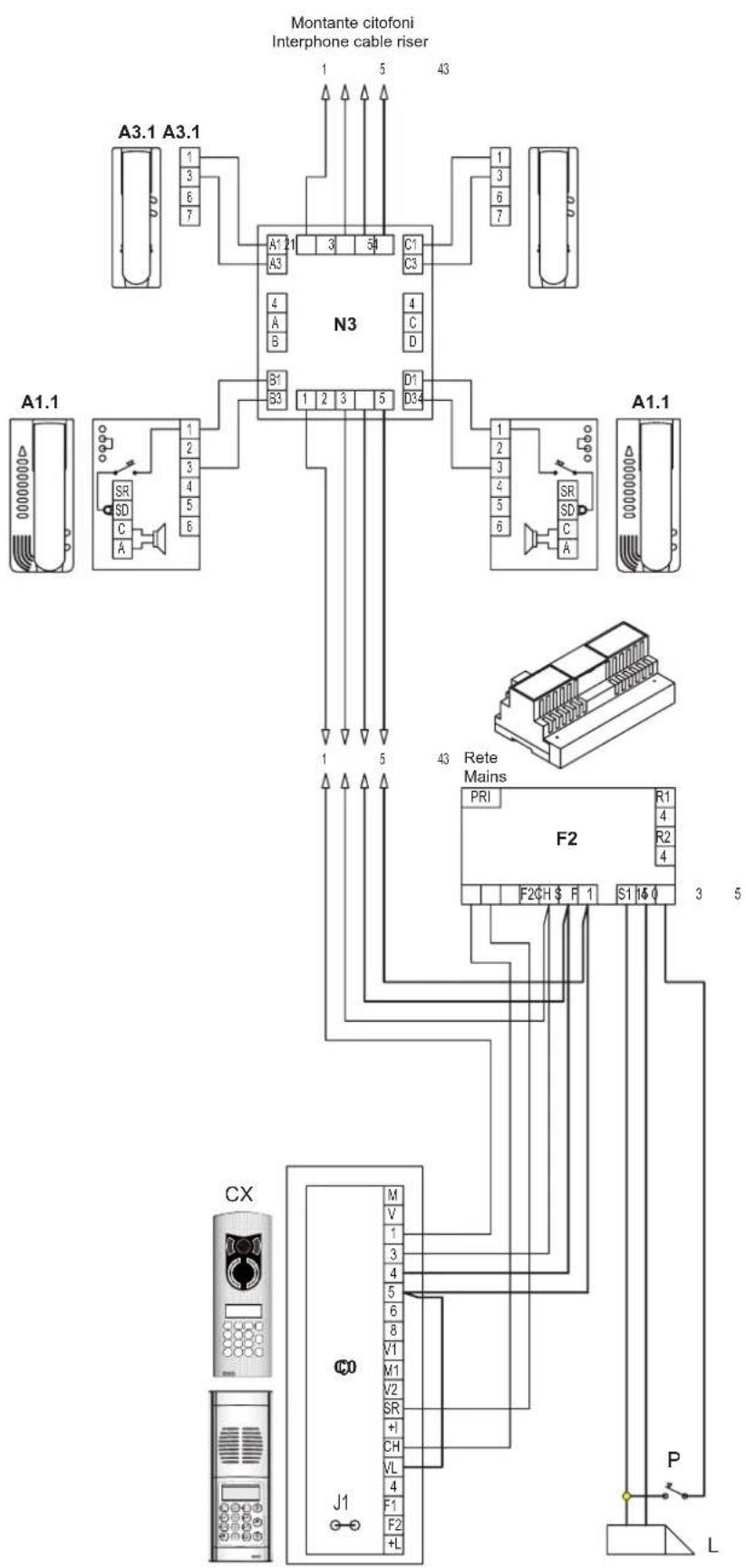
A1 - Petrarca series phone 6204
A1.0 - Petrarca series phone 62K4
A2 - 6600 series phone 6604/AU, 6704/AU
A3 - 8870 series phone 887B, 887B/1
C0 - Audio electronic unit with keypad and display 1282
CX - Entrance panel
DX - Entrance panel
L - Electric lock 12V A.C.
P - Additional push-button for lock
IMPIANTO CONDOMINIALE SEMPLICE CON DERIVATORE DIGITALE AL PIANO
SIMPLE RESIDENTIAL INSTALLATION WITH FLOOR DISTRIBUTORS EQUIPPED WITH INTERNAL DECODING.
flowchart
graph TD
    A["Montante citofoni Interphone cable riser"] --> B["A3.1 A3.1"]
    A --> C["A1.1"]
    A --> D["A1.1"]
    A --> E["CX"]
    A --> F["J1"]
    B --> G["N3"]
    C --> G
    D --> G
    E --> H["Rete Mains"]
    F --> H
    G --> I["F2"]
    H --> J["R1"]
    H --> K["R2"]
    H --> L["S1"]
    H --> M["S0"]
    I --> N["P"]
    J --> O["L"]
    K --> P["P"]
    L --> Q["L"]
    style A3.1 fill:#f9f,stroke:#333
    style A1.1 fill:#ccf,stroke:#333
    style CX fill:#cfc,stroke:#333
    style J1 fill:#fcc,stroke:#333
    style F fill:#cff,stroke:#333
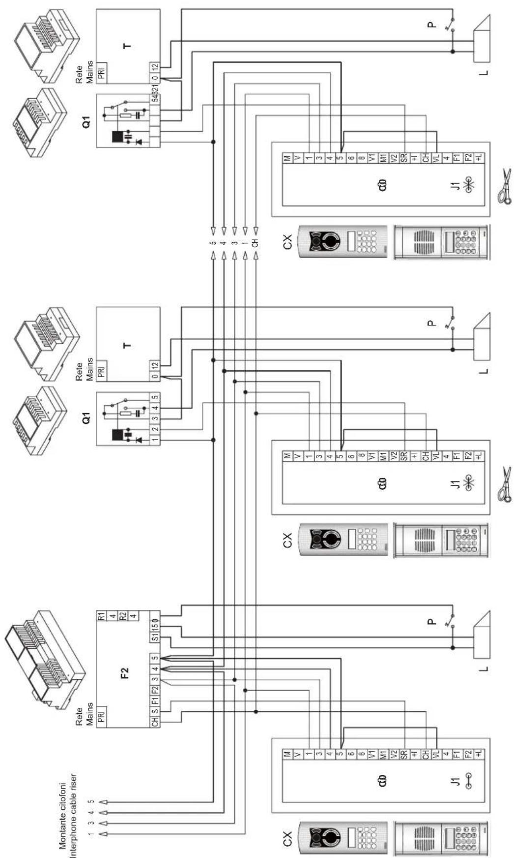
A3.1 - 8870 series phone 8877
C0 - Audio electronic unit with keypad and display 1282
CX - Entrance panel
DX - Entrance panel
L - Electric lock 12V A.C.
N3 - Distributor 949B
P - Additional push-button for lock
IMPIANTO CONDOMINIALE SEMPLICE CON DUE O PIÙ TARGHE IN PARALLELO SIMPLE RESIDENTIAL INSTALLATION WITH TWO OR MORE PANELS IN PARALLEL.
flowchart
graph TD
    A["Montante citofoni Interphone cable riser"] --> B["F2"]
    B --> C["Rete Mains"]
    C --> D["T"]
    D --> E["Q1"]
    E --> F["T"]
    F --> G["Q1"]
    G --> H["T"]
    H --> I["54B21"]
    I --> J["5"]
    J --> K["P"]
    K --> L["L"]
    L --> M["CX"]
    M --> N["J1"]
    N --> O["CX"]
    O --> P["Q1"]
    P --> Q["T"]
    Q --> R["Q1"]
    R --> S["54B21"]
    S --> T["P"]
    T --> U["L"]
    U --> V["CX"]
    V --> W["J1"]
    W --> X["CX"]
    X --> Y["Q1"]
    Y --> Z["T"]
    Z --> AA["Q1"]
    AA --> AB["L"]
    AB --> AC["P"]
C0 - Audio electronic unit with keypad and display 1282
CX - Entrance panel F2 - Power supply 6948 (6941)
L - Electric lock 12V A.C. P - Additional push-button for lock
T - Transformer M832 Q1 - Relay 0170/001
Rif. schema si030 Ref. diagram si030
IMPIANTO CONDOMINIALE CON UNA TARGA PRINCIPALE E DUE O PIÙ TARGHE A PIÈ SCALA (complesso edilizio). RESIDENTIAL INSTALLATION WITH ONE MAIN PANEL AND TWO OR MORE SECONDARY PANELS (BUILDING COMPLEX).
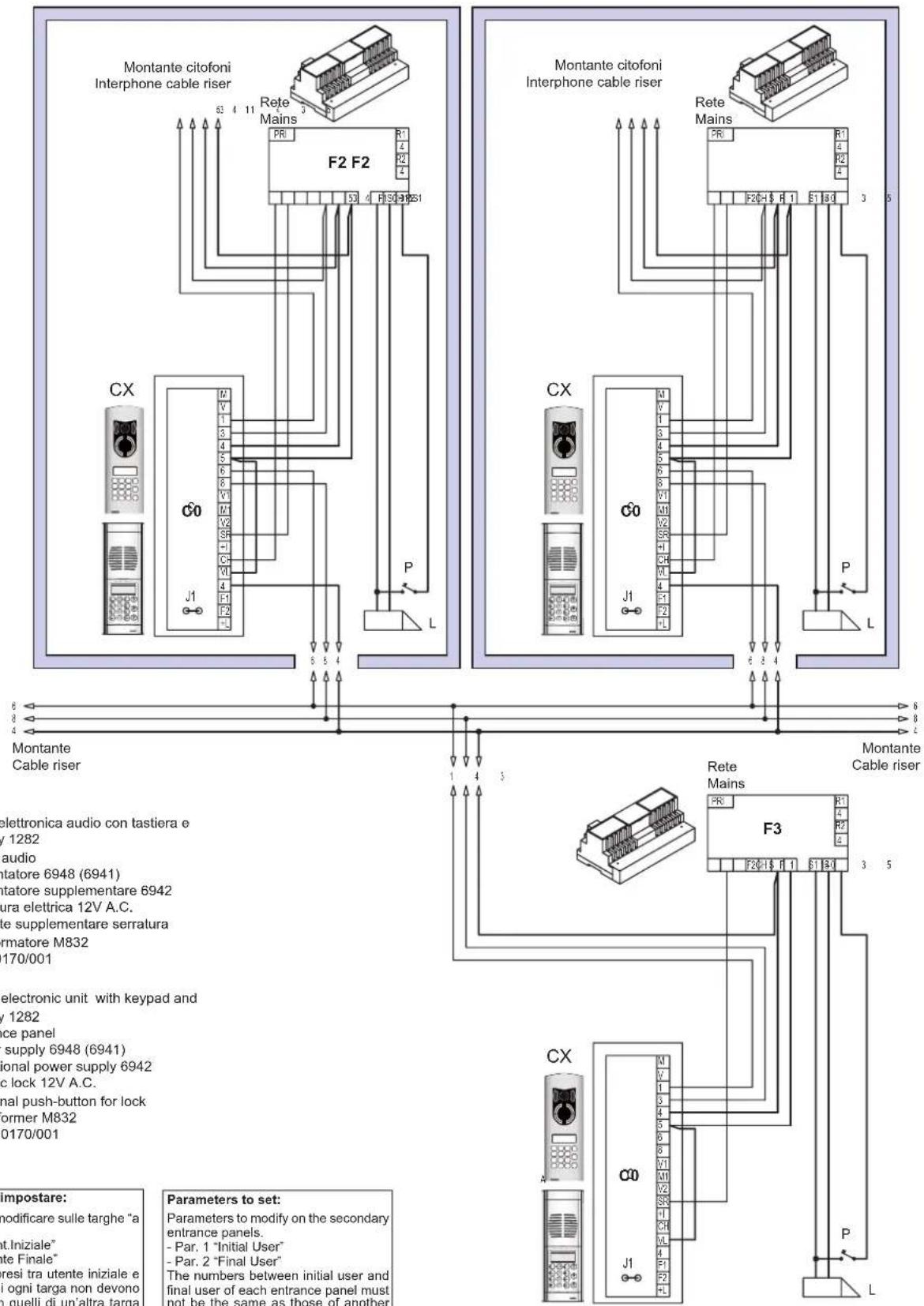
Parametri da impostare:
Parameters to modify on the secondary entrance panels.
- Par. 1 "Initial User"
- Par. 2 "Final User"
The numbers between initial user and final user of each entrance panel must not be the same as those of another secondary entrance panel.
Parameters to modify on the main entrance panel.
- Par. 19 "Conv. Duration"
The call time of the main entrance panel must be greater than the call time of the secondary panels (by at least one second).
Rif. schema si031
Ref. diagram si031
IMPIANTO CONDOMINIALE CON DUE O PIÙ TARGHE PRINCIPALI E DUE O PIÙ TARGHE A PIÈ SCALA (complesso edilizio). RESIDENTIAL INSTALLATION WITH TWO OR MORE MAIN PANELS AND TWO OR MORE SECONDARY PANELS (BUILDING COMPLEX).

flowchart
graph TD
    subgraph "Montante citofoni Interphone cable riser"
        A["CX"] --> B["C0"]
        B --> C["J1"]
        C --> D["L"]
        D --> E["P"]
        E --> F["L"]
    end

    subgraph "Montante citofoni Interphone cable riser"
        G["CX"] --> H["C0"]
        H --> I["J1"]
        I --> J["L"]
        J --> K["P"]
        K --> L["L"]
    end

    subgraph "Montante Cable riser"
        M["CX"] --> N["C0"]
        N --> O["J1"]
        O --> P["L"]
        P --> Q["P"]
        Q --> R["L"]
    end

    style A fill:#f9f,stroke:#333
    style B fill:#f9f,stroke:#333
    style H fill:#f9f,stroke:#333
    style I fill:#f9f,stroke:#333
    style N fill:#f9f,stroke:#333
    style O fill:#f9f,stroke:#333
    style P fill:#f9f,stroke:#333
    style Q fill:#f9f,stroke:#333
    style R fill:#f9f,stroke:#333
    style_S["F2"] --> T["Rete Mains"]
    S --> U["F2"]
    S --> V["F2"]
    T --> W["Rete Mains"]
    U --> X["Rete Mains"]
    V --> Y["Rete Mains"]
    W --> Z["Rete Mains"]
    X --> AA["Rete Mains"]
    Y --> AB["Rete Mains"]
    Z --> AC["Rete Mains"]
    AA --> AD["Rete Mains"]
    AB --> AE["Rete Mains"]
    AC --> AF["Rete Mains"]
    AD --> AG["Rete Mains"]
    AE --> AH["Rete Mains"]
    AF --> AI["Rete Mains"]
    AG --> AJ["Rete Mains"]
    AH --> AK["Rete Mains"]
    AI --> AL["Rete Mains"]
    AJ --> AM["Rete Mains"]
    AK --> AN["Rete Mains"]
    AL --> AO["Rete Mains"]
    AM --> AP["Rete Mains"]
    AN --> AQ["Rete Mains"]
    AO --> AR["Rete Mains"]
    AP --> AS["Rete Mains"]
    AQ --> AT["Rete Mains"]
    AR --> AU["Rete Mains"]

    note1["Montante Cable riser"]
    note2["C0 - Unità ele display"]
    note3["CX - Targa a"]
    note4["F2 - Alimenta"]
    note5["F3 - Alimenta"]
    note6["L - Serratura"]
    note7["P - Pulsante"]
    note8["T - Trasform"]
    note9["Q1 - Relè 01"]

    note10["C0 - Audio el display"]
    note11["CX - Entrance"]
    note12["F2 - Power s"]
    note13["F3 - Addiction"]
    note14["L - Electric le"]
    note15["P - Addition"]
    note16["T - Transfor"]
    note17["Q1 - Relay 01"]
NOTE: The last video distributor must be loaded with a 75 Ohm resistor connected to free terminal V.
B1 - Videocitofono serie 7200 7214
B2 - Videocitofono serie 6600
6614,6714,6624,6724,662D
B4 - Videocitofono serie Petrarca
6023 + 6204 + 6145, 6023 + 6204 + 6145
B5 - Videocitofono serie Giotto 6344, 6354
N1 - Distributore 5555
N2 - Distributore 5556/004
B1 - 7200 series monitor 7214
B2 - 6600 series monitor
6614,6714,6624,6724,662D
B4 - Petrarca series monitor
6023 + 6204 + 6145, 6023 + 6204 + 6145
B5 - Giotto series monitor 6344, 6354
N1 - Distributor 5555
N2 - Distributor 5556/004
MONTANTE MONITOR CON DISTRIBUTORE AL PIANO 949B MONITOR RISER WITH FLOOR DISTRIBUTOR 949B

flowchart
graph TD
    subgraph Montante videocitofoni
        A["Monitor cable riser"] --> B["B5.1"]
        A --> C["B2.1"]
    end
    subgraph N3
            D["N3"] --> E["V1"]
            D --> F["V2"]
            D --> G["V3"]
            D --> H["V4"]
            D --> I["V5"]
            D --> J["V6"]
            D --> K["V7"]
            D --> L["V8"]
            D --> M["V9"]
            D --> N["V10"]
            D --> O["V11"]
            D --> P["V12"]
            D --> Q["V13"]
            D --> R["V14"]
            D --> S["V15"]
            D --> T["V16"]
            D --> U["V17"]
            D --> V["V18"]
            D --> W["V19"]
            D --> X["V20"]
            D --> Y["V21"]
            D --> Z["V22"]
            D --> AA["V23"]
            D --> AB["V24"]
            D --> AC["V25"]
            D --> AD["V26"]
            D --> AE["V27"]
            D --> AF["V28"]
            D --> AG["V29"]
            D --> AH["V30"]
            D --> AI["V31"]
            D --> AJ["V32"]
            D --> AK["V33"]
            D --> AL["V34"]
            D --> AM["V35"]
            D --> AN["V36"]
            D --> AO["V37"]
            D --> AP["V38"]
            D --> AQ["V39"]
            D --> AR["V40"]
            D --> AS["V41"]
            D --> AT["V42"]
            D --> AU["V43"]
            D --> AV["V44"]
            D --> AW["V45"]
            D --> AX["V46"]
            D --> AY["V47"]
            D --> AZ["V48"]
            D --> BA["V49"]
            D --> BB["V50"]
            D --> BC["V51"]
            D --> BD["V52"]
            D --> BE["V53"]
            D --> BF["V54"]
            D --> BG["V55"]
            D --> BH["V56"]
            D --> BI["V57"]
            D --> BJ["V58"]
            D --> BK["V59"]
            D --> BL["V60"]
            D --> BM["V61"]
            D --> BN["V62"]
            D --> BO["V63"]
            D --> BP["V64"]
            D --> BQ["V65"]
            D --> BR["V66"]
            D --> BS["V67"]
            D --> BT["V68"]
            D --> BU["V69"]
            D --> BV["V70"]
            D --> BW["V71"]
            D --> BX["V72"]
            D --> BY["V73"]
            D --> BZ["V74"]
            D --> CA["V75"]
            BZ --> CB["CN1"]
    end
    subgraph N1/N2
        AD["Monitor cable riser"] --> AE
        AD --> AF
        AD --> AG
        AD --> AH
        AD --> AI
        AD --> AJ
        AD --> AK
        AD --> AL
        AD --> AM
        AD --> AN
        AD --> AO
        AD --> AP
        AD --> AQ
        AD --> AR
        AD --> AS
        AD --> AT
        AD --> AU
        AD --> AV
        AD --> AW
        AD --> AX
        AD --> AY
        AD --> AZ
        AD --> BA
        AD --> BB
        AD --> BC
        AD --> BD
        AD --> BE
        AD --> BF
        AD --> BG
        AD --> BH
        AD --> BI
        AD --> BJ
        AD --> BK
        AD --> BL
        AD --> BM
        AD --> BN
        AD --> BO
        AD --> BP
        AD --> AR
        AD --> AS
        AD --> AT
        AD --> AU
        AD --> AV
        AD --> AW
        AD --> AX
        AD --> AY
        AD --> AZ
        AD --> BA
        AD --> BB
        AD --> BC
        AD --> BD
        AD --> BE
        AD --> BF
        AD --> BG
        AD --> BH
        AD --> BI
        AD --> BJ
    end
Montante videocitofoni
Monitor cable riser
All'alimentatore 6948
To power supply 6948
N.B. L'ultimo distributore video deve essere caricato con la resistenza da 75 Ohm collegata al morsetto V libero.
NOTE: The last video distributor must be loaded with a 75 Ohm resistor connected to free terminal V.
B4.1 - Videocitofono serie Petrarca 6020 + 6145 + 6201
N1 - Distributore 5555
N2 - Distributore 5556/004
N3 - Distributore 949B
B4.1 - Petrarca series monitor 6020 + 6145 + 6201
N1 - Distributor 5555
N2 - Distributor 5556/004
N3 - Distributor 949B
Rif. schema si036.00 Ref. diagram si036.00
IMPIANTO CONDOMINIALE SEMPLICE CON VIDEOCITOFONI MUNITI DI DECODIFICA INTERNA SIMPLE RESIDENTIAL INSTALLATION WITH MONITORS EQUIPPED WITH INTERNAL DECODING.

6614,6714,6624,6724,662D
B2 - 6600 series monitor
6614,6714,6624,6724,662D
B4 - Petrarca series monitor
6023 + 6204 + 6145, 6023 + 6204 + 6145
B5 - Giotto series monitor 6344, 6354
D0 - Video electronic unit with keypad and display 1286
DX - Entrance panel
F1 - Power supply 6948
L - Electric lock 12V A.C.
N1 - Distributor 5555
N2 - Distributor 5556/004
P - Additional push-button for lock
IMPIANTO CONDOMINIALE SEMPLICE CON DERIVATORI AL PIANO MUNITI DI DECODIFICA INTERNA. SIMPLE RESIDENTIAL INSTALLATION WITH DISTRIBUTORS EQUIPPED WITH INTERNAL DECODING.
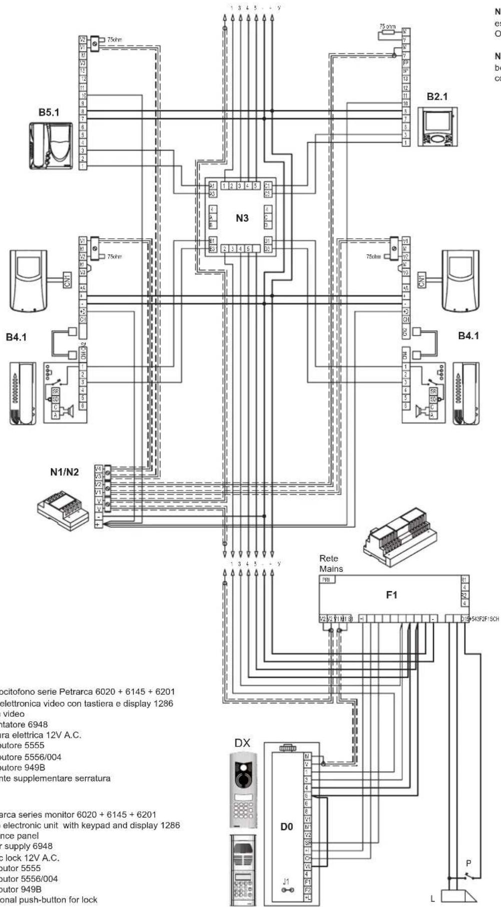
NOTE: The last video distributor must be loaded with a 75 Ohm resistor connected to free terminal V.
Rif. schema si034
Ref. diagram si034
B4.1 - Petrarca series monitor 6020 + 6145 + 6201
D0 - Video electronic unit with keypad and display 1286
DX - Entrance panel
F1 - Power supply 6948
L - Electric lock 12V A.C.
N1 - Distributor 5555
N2 - Distributor 5556/004
N3 - Distributor 949B
P - Additional push-button for lock
IMPIANTO CONDOMINIALE SEMPLICE CON DUE O PIÙ TARGHE IN PARALLELO SIMPLE RESIDENTIAL INSTALLATION WITH TWO OR MORE PANELS IN PARALLEL

flowchart
graph TD
    A["Montante videocitofoni Monitor cable riser"] --> B["5Q3"]
    B --> C["F1"]
    C --> D["F3"]
    D --> E["T"]
    subgraph Module_F1
        F1 --> G["F1"]
        G --> H["F3"]
    end
    subgraph Module_F3
        I1 --> J1
        J1 --> K1
        K1 --> L1
    end
    subgraph DDX_D0
        M1 --> N1
        M2 --> O1
        M3 --> P1
        M4 --> Q1
    end
    subgraph DDX_D0
        R1 --> S1
        R2 --> T1
        R3 --> U1
        R4 --> V1
        R5 --> W1
        R6 --> X1
        R7 --> Y1
        R8 --> Z1
        R9 --> AA1
    end
    subgraph DDX_D0
        AB1 --> AC1
        AB2 --> AD1
        AB3 --> AE1
        AB4 --> AF1
        AB5 --> AG1
        AB6 --> AH1
        AB7 --> AI1
        AB8 --> AJ1
        AB9 --> AK1
    end
F5 - Addictional power supply 6982
C - Audio electronic unit with push-buttons 1283
CX - Entrance panel
D0 - Video electronic unit with keypad and display 1286
DX - Entrance panel
F1 - Power supply 6948
F3 - Addictional power supply 6942
F5 - Addictional power supply 6982
L - Electric lock 12V A.C.
N2 - Distributor 5556/004
P - Additional push-button for lock
Parametri da impostare:
Parameters to modify on the secondary entrance panels.
- Par. 1 "Initial User"
- Par. 2 "Final User"
The numbers between initial user and final user of each entrance panel must not be the same as those of another secondary entrance panel.
Parameters to modify on the main entrance panel.
- Par. 19 "Conv. Duration"
The call time of the main entrance panel must be greater than the call time of the secondary panels (by at least one second).
IMPIANTO CONDOMINIALE CON UNA TARGA PRINCIPALE E DUE O PIÙ TARGHE A PIÈ SCALA (Complesso edilizio).
RESIDENTIAL INSTALLATION WITH ONE MAIN PANEL AND TWO OR MORE STAIRWAY PANELS (BUILDING COMPLEX).
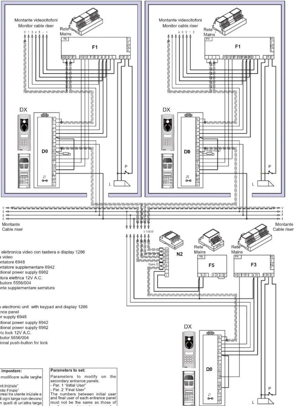
F5 - Addictional power supply 6982
D0 - Video electronic unit with keypad and display 1286
DX - Entrance panel
F1 - Power supply 6948
F3 - Addictional power supply 6942
F5 - Addictional power supply 6982
L - Electric lock 12V A.C.
N2 - Distributor 5556/004
P - Additional push-button for lock
Parametri da impostare:
Parameters to modify on the secondary entrance panels.
- Par. 1 "Initial User"
- Par. 2 "Final User"
The numbers between initial user and final user of each entrance panel must not be the same as those of another secondary entrance panel.
Parameters to modify on the main entrance panel.
- Par. 19 "Conv. Duration"
The call time of the main entrance panel must be greater than the call time of the secondary panels (by at least one second).
Rif. schema si038
Ref. diagram si038
IMPIANTO CONDOMINIALE CON DUE O PIÙ TARGA PRINCIPALE VIDEO E DUE O PIÙ TARGHE A PIÈ SCALA VIDEO O AUDIO
INSTALLATION FOR BLOCK OF FLATS WITH TWO OR MORE MAIN VIDEO ENTRANCE PANELS OR MORE VIDEO OR AUDIO OUTDOOR ENTRANCE PANEL (BUILDING COMPLEX).

flowchart
graph TD
    subgraph "Monitor cable riser"
        A["DX"] --> B["D0"]
        B --> C["P"]
        C --> D["L"]
        D --> E["P"]
        E --> F["Montante Cable riser"]
    end

    subgraph "Monitor cable riser"
        G["DX"] --> H["D0"]
        H --> I["P"]
        I --> J["L"]
        J --> K["P"]
        K --> L["Montante Cable riser"]
    end

    subgraph "Video electronic unit with keypad and display 1286"
        M["DX"] --> N["Entrance panel"]
        N --> O["F1 - Power supply 6948"]
        O --> P["F3 - Addictional power supply 6942"]
        P --> Q["F5 - Addictional power supply 6982"]
        Q --> R["L - Electric lock 12V A.C."]
        R --> S["N2 - Distributor 5556/004"]
        S --> T["P - Additional push-button for lock"]
        T --> U["T - Transformer M832"]
        U --> V["Q1 - Relay 0170/001"]
        V --> W["Q3 - Relay 0170/051"]

    subgraph "Distribution 5556/004"
        X["DX"] --> Y["D0"]
        Y --> Z["P"]
        Z --> AA["L"]
        AA --> AB["P"]
        AB --> AC["Montante Cable riser"]
    end

    subgraph "Parameters to set"
        AD["DX"] --> AE["D0"]
        AE --> AF["P"]
        AF --> AG["L"]
        AG --> AH["P"]
        AH --> AI["Montante Cable riser"]
    end

    style "Monitor cable riser" fill:#f9f,stroke:#333
    style "Video electronic unit with keypad and display 1286" fill:#ccf,stroke:#333
    style "Distribution 5556/004" fill:#cfc,stroke:#333
    style "Parameters to set" fill:#fcc,stroke:#333

Disconnect the metal jumper located on the side of the terminal block.
Parametri da impostare:
Parameters to modify on the secondary entrance panels.
- Par. 1 "Initial User"
- Par. 2 "Final User"
The numbers between initial user and final user of each entrance panel must not be the same as those of another secondary entrance panel.
Parameters to modify on the main entrance panel.
- Par. 19 "Conv. Duration"
The call time of the main entrance panel must be greater than the call time of the secondary panels (by at least one second).
Connection of auxiliary functions F1 - F2 in systems equipped with internal decoding or without internal decoding.
In some cases, enabling the functions requires the addition of supplementary buttons and connections to be made in addition to the basic connections. Interphones type 6204 and 6201 are fitted as standard with only the lock release button; for the use of a second auxiliary function, it is necessary to add button 6152 (pack containing 8 N.O. push-button in interphones type 6201 and type 6C59 (pair of N.O. push-buttons) in interphones type 6204. It is possible to activate an auxiliary function F1 controlled by the interphones or monitors by connecting a relay 0170/001 as shown in the diagram (terminals R1-4 of the power supply unit).
| During programming of the entrance panel it is possible to change the following two parameters: | |||
| Par. 21 | T_F1 | Funct.1 activation time | F1 function activation duration in seconds (F1 line) |
| Par. 22 | T_F2 | Funct.2 activation time | F2 function activation duration in seconds (F2 line) |
The buttons "F1" and 🙏 activate the function F1. The buttons "F2" and □ activate function F2.
Citofoni con codifica interna Interphones with internal coding

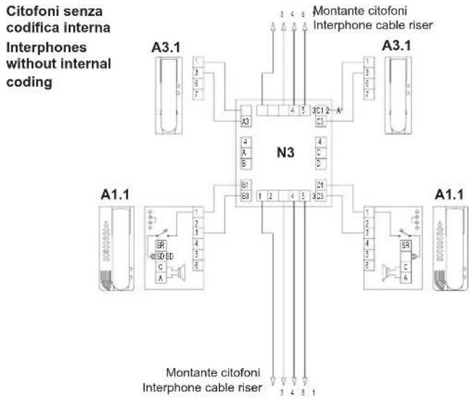
flowchart
graph TD
    A["A3.1"] --> B["Interphone Cable Riser"]
    C["A3.1"] --> D["Interphone Cable Riser"]
    E["A1.1"] --> F["Interphone Cable Riser"]
    G["A1.1"] --> H["Interphone Cable Riser"]
    I["Montante citofoni Interphone cable riser"] --> J["Interphone Cable Riser"]
    K["Montante citofoni Interphone cable riser"] --> L["Interphone Cable Riser"]
    M["Montante citofoni Interphone cable riser"] --> N["Interphone Cable Riser"]
Collegamento relè per funzioni supplementari targa esterna
Connection of relays for additional functions
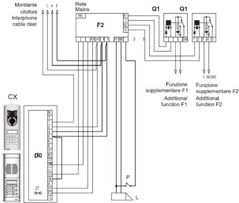
flowchart
graph TD
    A["Montante citofoni Interphone cable riser"] --> B["F2"]
    B --> C["Q1"]
    C --> D["Q1"]
    D --> E["Funzione supplementare F1 Additional function F1"]
    D --> F["Funzione supplementare F2 Additional function F2"]
    G["CX"] --> H["D0"]
    H --> I["J1"]
    I --> J["P"]
    J --> K["L"]
    L["Rete Mains"] --> M["F2"]
    M --> N["Q1"]
    N --> O["Q1"]
    P["CX"] --> Q["M"]
    Q --> R["V"]
    R --> S["1"]
    S --> T["3"]
    T --> U["4"]
    U --> V["5"]
    V --> W["6"]
    W --> X["8"]
    X --> Y["V1"]
    Y --> Z["M"]
    Z --> AA["V2"]
    AA --> AB["S"]
    AB --> AC["+"]
    AC --> AD["C1"]
    AD --> AE["V1"]
    AE --> AF["4"]
    AF --> AG["F1"]
    AG --> AH["F2"]
    AH --> AI["L"]
Wiring diagram for connection of Digibus sytem electronic entrance panel with keypad and additional numerical display with luminous name-tag for 13 names type 805N or for street number type 80PN.
The additional power supply type 6582 is used to power the LEDs for the name-tags lighting when there are more than 5 additional name-tags modules (type 12TS, or 12TD) or more than 5 additional name-tags modules (type 805N, or 80PN). One power supply type 6582 can power up to 30 modules of panel with name-tags modules (type 12TS, or 12TD) or up to 65 modules of panel with name-tags modules (type 805N, or 80PN)
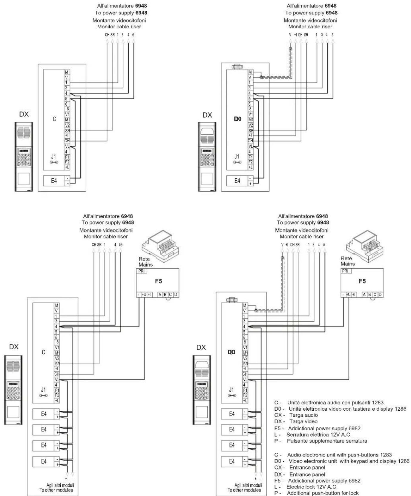
The instruction manual is downloadable from the site www.vimar.com
Installation rules
Installation should be carried out by qualified personnel in compliance with the current regulations regarding the installation of electrical equipment in the country where the products are installed.
Conformity
EMC directive
Standards EN 61000-6-1 and EN 61000-6-3.

WEEE - Information for users
If the crossed-out bin symbol appears on the equipment or packaging, this means the product must not be included with other general waste at the end of its working life. The user must take the worn product to a sorted waste center, or return it to the retailer when purchasing a new one. Products for disposal can be consigned free of charge (without any new purchase obligation) to retailers with a sales area of at least 400m², if they measure less than 25cm. An efficient sorted waste collection for the environmentally friendly disposal of the used device, or its subsequent recycling, helps avoid the potential negative effects on the environment and people's health, and encourages the re-use and/or recycling of the construction materials.
- Description
- The electronic units are to be used with 1200 series or modular 8000 series plates and components, supplied separately.
- Entrance panel operating characteristics
- ELECTRONIC UNIT
- TERMINAL BLOCK
- Terminal Description
- PRELIMINARY OPERATIONS
- (only for versions 1282/P and 1286/P)
- PROGRAMMING THE HARDWARE OF ADDITIONAL PUSH-BUTTON MODULES
- (make changes with system switched off)
- PROCEDURE FOR ACCESSING ENTRANCE PANEL FUNCTIONS
- QUICK FUNCTION BUTTONS
- THE PANEL SETUP MENUS
- PROGRAMMING ENTRANCE PANEL TECHNICAL PARAMETERS
- ACCESSING THE ENTRANCE PANEL PARAMETER MENU
- PROGRAMMING WITH "ANALYZER"
- ENTRANCE PANEL PARAMETERS
- DESCRIPTION OF FUNCTIONS AND PARAMETERS
- Connection of entrance panels in parallel in building-complex systems:
- Entrance panel code "Panel Number" (3).
- Pre-code (4) and number of pre-code digits (22).
- Enable camera "Enab. Camera" (16).
- Enable entrance panel tone "Enab. Panel Tone" (17).
- Enable Self-start "Enab. Self-start" (18).
- Enable Switchboard Call "Enab.Switchboard Call" (19), Switchboard call button "Switchbd button" (20).
- -1286
- Backlight minimum brightness "Min LED Lux (%)" (32).
- First number in memory "1 Num. Memory" (47).
- Second number in memory "2 Num. Memory" (48).
- ENTRANCE PANEL VOLUME ADJUSTMENT
- PROGRAMMING KEYCODES
- To program a key:
- To modify a key:
- To modify the entrance panel optional data:
- ERASING ALL KEYCODES
- HARDWARE – SOFTWARE ASSOCIATION
- (Only for version 1282/P and 1286/P)
- ENTRANCE PANEL HW - SW ASSOCIATION MENU
- PROGRAMMING WITH 950B
- OPERATING MODES
- PROGRAMMING TIME BANDS
- PROGRAMMING THE TIME BAND
- DAY OF THE WEEK
- FIRST TIME WINDOW
- SECOND TIME WINDOW
- AGENDA PROGRAMMING AND USE
- Accessing the agenda management menu
- Inserting a new user
- Deleting an inserted user
- Erasing the agenda
- Using the agenda
- Parametri da impostare:
- MONTANTE MONITOR CON DISTRIBUTORE AL PIANO 949B MONITOR RISER WITH FLOOR DISTRIBUTOR 949B
- Wiring diagram for connection of Digibus sytem electronic entrance panel with keypad and additional numerical display with luminous name-tag for 13 names type 805N or for street number type 80PN.
- Installation rules
- Conformity
- WEEE - Information for users
Brand : Vimar
Model : ELVOX 1282
Category : Video Intercom