QCI 3 - Speaker TANNOY - Free user manual and instructions
Find the device manual for free QCI 3 TANNOY in PDF.
Download the instructions for your Speaker in PDF format for free! Find your manual QCI 3 - TANNOY and take your electronic device back in hand. On this page are published all the documents necessary for the use of your device. QCI 3 by TANNOY.
USER MANUAL QCI 3 TANNOY
2 QCI 3/QCI 8DC/PCI 8DC
Terminals marked with this symbol carry electrical current of sucient magnitude to constitute risk of electric shock. Use only high-quality professional speaker cables with ¼" TS or twist-locking plugs pre-installed. Allother installation or modication should be performed only by qualiedpersonnel. This symbol, wherever it appears, alerts you to the presence of uninsulated dangerous voltage inside the enclosure - voltage that may be sucient to constitute a risk ofshock. This symbol, wherever it appears, alerts you to important operating and maintenance instructions in the accompanying literature. Please read themanual. Caution To reduce the risk of electric shock, do not remove the top cover (or the rear section). No user serviceable parts inside. Refer servicing to qualiedpersonnel. Caution To reduce the risk of re or electric shock, do not expose this appliance to rain and moisture. Theapparatus shall not be exposed to dripping or splashing liquids and no objects lled with liquids, such as vases, shall be placed on the apparatus. Caution These service instructions are for use by qualied service personnel only. Toreduce the risk of electric shock do not perform any servicing other than that contained in the operation instructions. Repairshave to be performed by qualied servicepersonnel.
1. Read these instructions.
2. Keep these instructions.
3. Heed all warnings.
4. Follow all instructions.
5. Do not use this apparatus near water.
6. Clean only with dry cloth.
7. Do not block any ventilation openings.
Install in accordance with the manufacturer’s instructions.
8. Do not install near any heat sources
such as radiators, heat registers, stoves, or other apparatus (including ampliers) that produce heat.
9. Do not defeat the safety purpose of the
polarized or grounding-type plug. A polarized plug has two blades with one wider than the other. A grounding-type plug has two blades and a third grounding prong. The wide blade or the third prong are provided for your safety. Ifthe provided plug does not t into your outlet, consult an electrician for replacement of the obsolete outlet.
10. Protect the power cord from being
walked on or pinched particularly at plugs, convenience receptacles, and the point where they exit from the apparatus.
11. Use only attachments/accessories
specied by themanufacturer.
12. Use only with the cart,
stand, tripod, bracket, or table specied by the manufacturer, or sold with the apparatus. When a cart is used, use caution when moving the cart/ apparatus combination to avoid injury from tip-over.
13. Unplug this app aratus during lightning
storms or when unused for long periods of time.
14. Refer all servicing to qualied service
personnel. Servicing is required when the apparatus has been damaged in any way, such as power supply cord or plug is damaged, liquid has been spilled or objects have fallen into the apparatus, the apparatus has been exposed to rain or moisture, does not operate normally, or has beendropped.
15. The apparatus shall be connected to
a MAINS socket outlet with a protective earthing connection.
16. Where the MAINS plug or an appliance
coupler is used as the disconnect device, the disconnect device shall remain readily operable.
17. Correct disposal of this
product: This symbol indicates that this product must not be disposed of with household waste, according to the WEEE Directive (2012/19/EU) and your national law. This product should be taken to a collection center licensed for the recycling of waste electrical and electronic equipment (EEE). The mishandling of this type of waste could have a possible negative impact on the environment and human health due to potentially hazardous substances that are generally associated with EEE. At the same time, your cooperation in the correct disposal of this product will contribute to the ecient use of natural resources. For more information about where you can take your waste equipment for recycling, please contact your local city oce, or your household waste collection service.
18. Do not install in a conned space, such as
a book case or similar unit.
19. Do not place naked ame sources, such
as lighted candles, on the apparatus.
20. Please keep the environmental aspects
of battery disposal in mind. Batteries must be disposed-of at a battery collection point.
4 QCI 3/QCI 8DC/PCI 8DC
6 QCI 3/QCI 8DC/PCI 8DC
BESCHRÄNKTE GARANTIE
Die geltenden Garantiebedingungen und zusätzliche Informationen bezüglich der von Music Tribe gewährten beschränkten Garantie nden Sie online unter community.musictribe. com/pages/support#warranty Aviso! Terminais marcados com o símbolo carregam corrente elétrica de magnitude suciente para constituir um risco de choque elétrico. Use apenas cabos de alto-falantes de alta qualidade com plugues TS de ¼" ou plugues com trava de torção pré-instalados. Todas as outras instalações e modicações devem ser efetuadas por pessoasqualicadas. Este símbolo, onde quer que o encontre, alerta-o para a leitura das instruções de manuseamento que acompanham o equipamento. Por favor leia o manual deinstruções. Atenção De forma a diminuir o risco de choque eléctrico, nãoremover a cobertura (ouasecção de trás). Não existem peças substituíveis por parte do utilizador no seu interior. Para esse efeito recorrer a um técnicoqualicado. Atenção Para reduzir o risco de incêndios ou choques eléctricos o aparelho não deve ser exposto à chuva nem à humidade. Alémdisso, não deve ser sujeito a salpicos, nem devem ser colocados em cima do aparelho objectos contendo líquidos, taiscomojarras. Atenção Estas instruções de operação devem ser utilizadas, emexclusivo, por técnicos de assistência qualicados. Para evitar Wichtige Sicherheitshinweise Instruções de Segurança Importantes9Quick Start Guide
8 QCI 3/QCI 8DC/PCI 8DC
10 QCI 3/QCI 8DC/PCI 8DC
12 QCI 3/QCI 8DC/PCI 8DC
- Premium, high-definition loudspeaker for ceiling installation applications • 8" Dual Concentric driver featuring Tannoy point-source symmetrical dispersion technology • Tulip Waveguide enhances the point source symmetrical dispersion properties, providing exceptional high frequency clarity and articulation • Blue Kevlar® cone with high-excursion, rubber surround for high power handling • 3-way variable HF switch for customised performance preferences QCI 8DC
- High-performance loudspeaker for ceiling installation applications • 8" Dual Concentric driver featuring Tannoy Omnimagnet technology • Polypropylene cone with rubber surround for high-excursion linearity QCI 3
- High-performance loudspeaker for in-ceiling installation applications • 3" full-range driver with high excursion rubber surround • Glass fibre cone for excellent sound quality and dynamic full range performance • Compact, small footprint design for smaller spaces Common Features:
- Extremely thin bezel for discreet installation • Includes round and square baffles and grilles for versatile applications • Rigid chassis for improved bass performance and durable application • Integrated construction for easy installation • Semi matt white finish fits unobtrusively in any environment • Powder coated UV resistant perforated steel mesh grille with dust protection • Removable grilles for custom painting • Self-aligning clamp mounting system • Optional Tannoy logo grille badge included Unpacking Every Tannoy product and accessory is carefully inspected before packing. After unpacking, please inspect your product to make sure no damage has occurred in transit. In the unlikely event of any damage, would you please notify your dealer immediately and retain your shipping carton, as your dealer may ask you to return the faulty unit to them for inspection. Safety Notices Some regional construction codes require the use of a secondary method of securing loudspeakers in ceiling to provide security of a backup support. A secondary support line should be attached from the rear of the product to a source point on the ceiling. Please consult the relevant construction codes in your region. When using a power driver to install the product it is essential to use the correct torque level settings to avoid over tightening and damage to the ceiling material or clamps. Recommended torque setting: 1.5 Nm. Tannoy will not be held responsible for any damages caused by the improper installation of these loudspeakers. 15Quick Start Guide
1. WARNING: To avoid potential damage to your loudspeaker, ensure that the amplier is switched OFF prior to
connecting or disconnecting any cables.
2. Before switching the amplier ON, double check that all connections are secure and that the polarity is correct.
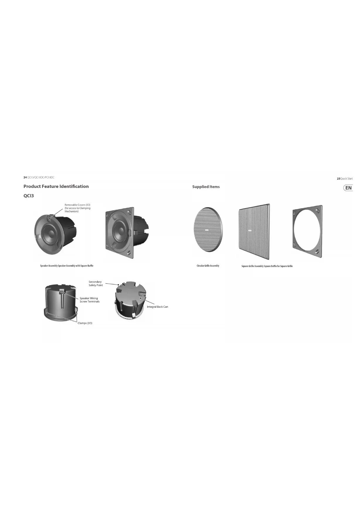
3. Note: For each speaker in this series, the correct square or circular bae has to be tted before connecting the
speaker wiring. (The baes are tted from behind, and so the speaker wires cannot be connected while the baes are being installed.)
4. The two screw terminals on the rear of each speaker are labled positive (+) and negative (-). These connect
respectively to the positive (+) and negative (-) output terminals of your audio power amplier.
5. Strip o approximately 8 mm (¼") of the outer protective layer of one conductor and twist its inner cores
together to prevent shorting from stray wires. Insert the core into the screw terminal while ensuring that correct polarity is maintained. Repeat this for both speaker wires. Tighten the two screws to make a secure connection.
6. The screw terminals for the QCI3 and QCI 8DC are located on the rear of each speaker. The screw terminals for the
PCI 8DC are located on the speaker frame. The PCI 8DC frame can be preinstalled and wired up, and the speaker assembly added at a later stage. QCI3 Terminals QCI 8DC Terminals PCI 8DC Terminals Installation QCI3
1. WARNING: To avoid potential damage to your loudspeaker, ensure that the amplier is switched OFF prior to
connecting or disconnecting any cables.
2. The procedure below describes the installation of the QCI3 speaker into a typical stud ceiling or wall with
drywall/plasterboard.
3. Locate a suitable mounting position for the speaker, using a stud-nder.
WARNING: Make sure that there are no power lines, other cables, or plumbing such as water, sewer, gas lines in
the chosen cutout location. Also make sure that the location is far enough from the closest wall stud so that the clamping mechanism can operate without interference.
4. Carefully mark and cutout a 117 mm (4.6") diameter hole in the drywall/plasterboard, and remove any debris.
5. Run the speaker wire from your amplier to this location, leaving enough slack to allow for the connection.
6. To use the square speaker grille, push the speaker into the supplied square bae.
The circular grille does not need a circular bae, as it ts directly over the speaker. Square Bae 31Quick Start Guide 30 QCI 3/QCI 8DC/PCI 8DC7. Pull out the 3 covers from the front of the speaker which hide the clamping system.
8. Each clamp can move up and down in its slot by rst pulling out the “cable-ties” from their tucked (stowed) position,
and releasing the tab. With the tab held, move each clamp backwards down the slot as far as it will go, so the clamps will be at the rear of the can, and inside the diameter of the cutout hole.
9. Follow the information on the previous pages to connect the speaker wires from your power amplier to the
speaker terminals. Make sure to check that the polarity is correct and that the positive and negative wires are securely and correctly connected.
10. Press the speaker (or speaker and square bae assembly) into the cutout hole in the wall, making sure that the
speaker wires are not trapped.
11. Pull the clamp cable-ties forward as far as they will go. This will move the clamps forward and secure the
speaker to the wall. Covers (X3) Cable-ties (X3) Release Tab Release Tab UP Cable-tie in tucked position Cable-tie pulled out
12. CAUTION: do not cut o the excess cable-tie length, or the clamps can no longer be reused. Instead, tuck the excess
length back into the slots and then re-install the three covers. 13. To remove the speaker at any time, remove the three covers, pull the cable-ties out of their tucked position, and then press the tabs, and this will allow you to pull the speaker forwards and out of the hole.
14. Install the circular grille by pressing it over the speaker. Small magnets hold it in place.
Covers (X3) Cable-ties (X3) tucked Magnets (X4) 33Quick Start Guide 32 QCI 3/QCI 8DC/PCI 8DC15. Alternatively, install the square grille by pressing it over the square bae. Small magnets in the speaker surround and the square bae hold it in place. Note: After installation, if the square bae does not press at against the drywall, insert a ½" long screw in the oval depression in each corner of the bae, and hand-tighten until the bae is at against the drywall. Magnets (X8) Insert extra screw here, if required (see note) INSTALLATION QCI 8DC
1. WARNING: To avoid potential damage to your loudspeaker, ensure that the amplier is switched OFF prior to
connecting or disconnecting any cables.
2. The procedure below describes the installation of the speaker into a typical stud ceiling or wall with
drywall/plasterboard.
3. Locate a suitable mounting position for the speaker, using a stud-nder.
WARNING: Make sure that there are no power lines, other cables, or plumbing such as water, sewer, gas lines in
the chosen cutout location. Also make sure that the location is far enough from the closest wall stud so that the clamping mechanism can operate without interference.
4. Use the supplied cutout template as a guide, and cut out a circular hole in the drywall/plasterboard. Remove any
debris from the hole. Use a suitable adhesive in the local area inside the hole to seal the drywall to the studs and joists, to prevent ceiling buzzing.
5. Run the speaker wire from your amplier to this location, leaving enough slack to allow for the connection.
Cutout Installation Template 35Quick Start Guide 34 QCI 3/QCI 8DC/PCI 8DC6. To use the square speaker grille, rst move the mounting clamps out of the way by undoing the four screws accessible from the front of the speaker. Remove the backing from the strips of double-sided tape, and push the speaker into the supplied square bae.
7. If you want to use the circular speaker grille, install the supplied circular bae instead.
8. Follow the information on the previous pages to connect the speaker wires from your power amplier to the speaker
terminals. Make sure to check that the polarity is correct and that the positive and negative wires are securely and correctly connected.
9. Make sure that the clamps are all in their rest position, then press the speaker/bae assembly into the cutout hole in
the wall, making sure that the speaker wires are not trapped. Clamp Screws (X4) Square Bae Square Bae and Speaker Circular Bae Circular Bae and Speaker
10. Tighten the four screws accessable from the front of the speaker, until all four clamps are holding the
speaker in place. As the screws are tightened, the clamps rotate out of their rest postion and clamp to the drywall/plasterboard. Note: After installation, if the square bae does not press at against the drywall, insert a ½" long screw in the oval depression in each corner of the bae, and hand-tighten until the bae is at against the drywall.
11. Install the square grille by pressing it into the square bae. Small magnets hold it in place.
Clamp Screws (X4) Insert extra screw here, if required (see note) 37Quick Start Guide 36 QCI 3/QCI 8DC/PCI 8DC12. Alternatively, Install the circular grille by pressing it into the circular bae. Small magnets hold it in place.
13. The grilles may be painted to match the decor, before they are tted onto the speaker bae.
14. Use the supplied square or circular masks to help protect the speaker cones when painting.
Painting Masks in Place INSTALLATION PCI 8DC
1. WARNING: To avoid potential damage to your loudspeaker, ensure that the amplier is switched OFF prior to
connecting or disconnecting any cables.
2. The procedure below describes the installation of the speaker into a typical stud ceiling with drywall/
plasterboard. The PCI 8DC speaker frame is installed and wired, then the speaker assembly can be added later.
3. Locate a suitable mounting position for the speaker, using a stud-nder. WARNING: Make sure that there are no
power lines, other cables, or plumbing such as water, sewer, gas lines in the chosen cutout location. Also make sure that the location is far enough from the closest wall stud so that the clamping mechanism can operate without interference.
4. Use the supplied cutout template as a guide, and cut out a circular hole in the drywall/plasterboard. Remove any
debris from the hole. Use a suitable adhesive in the local area inside the hole to seal the drywall to the studs and joists, to prevent ceiling buzzing.
5. Run the speaker wire from your amplier to this location, leaving enough slack to allow for the connection.
Cutout Installation Template 39Quick Start Guide 38 QCI 3/QCI 8DC/PCI 8DC6. To use the square speaker grille, rst move the mounting clamps out of the way as described in step 9 below. Remove the backing from the strips of double-sided tape, and push the speaker frame into the supplied square bae.
7. To use the circular speaker grille, push the speaker frame into the supplied circular bae instead.
Speaker Frame Square Bae Speaker Frame with Square Bae Speaker Frame Circular Bae Speaker Frame with Circular Bae
8. Follow the information on the previous pages to connect the speaker wires from your power amplier to the speaker
terminals on the speaker frame. Make sure to check that the polarity is correct and that the positive and negative wires are securely and correctly connected. Secure the speaker wiring to the rear ring of the frame with tie-wraps to prevent movement.
9. Carefully press the speaker frame into the cutout hole, making sure the speaker wires are not pinched. Reach
inside the frame and rotate the clamps outwards and pull the clamps forward on their rails to secure the speaker frame to the drywall/plasterboard. To remove the speaker frame from the hole, press the release tabs and push the clamps back. PCI 8DC Terminals Clamps (X4) Clamp Rail Release 41Quick Start Guide 40 QCI 3/QCI 8DC/PCI 8DC10. Use the supplied square or circular masks to help protect the speaker cones when painting.
11. The grilles can be painted separately.
12. To mount the speaker into the mounted speaker frame, align the connecter on the speaker, with the
corresponding connector on the speaker frame. Painting Masks in Place Alignment guide
13. To lock the speaker in place in the frame, press down on the three lock buttons on the front of the speaker.
Note: After installation, if the square bae does not press at against the drywall, insert a ½" screw in the oval depression in each corner of the bae, and hand-tighten until the bae is at against the drywall.
14. To unlock the speaker from the speaker frame, rst support the weight of the speaker, and rotate each lock with
a screwdriver less than half a turn.
15. The HF switch has three positions, with 0 dB being at. Adjust as necessary to suit the room position
and acoustic conditions. Locks Press in to Lock Turn to unlock HF switch HF Switch +1.5 dB 0 dB +3 dB Insert extra screw here, if required (see note) 43Quick Start Guide 42 QCI 3/QCI 8DC/PCI 8DC4216. Install the square grille by pressing it into the square bae. Small magnets hold it in place. Alternatively, install the circular grille by pressing it into the circular bae. QCI3 Terminals QCI 8DC Terminals PCI 8DC Terminals Cableado y conguración Conexiones de terminales
Covers (X3) Cable-ties (X3) tucked Magnets (X4)
Painting Masks in Place INSTALLATION PCI 8DC
5. Run the speaker wire from your amplier to this location, leaving enough slack to allow for the connection.
alto-falante na parede. Covers (X3) Cable-ties (X3) Release Tab Release Tab UP Cable-tie in tucked position Cable-tie pulled out
Painting Masks in Place INSTALAÇÃO PCI 8DC
Speaker Frame Square Bae Speaker Frame with Square Bae Speaker Frame Circular Bae Speaker Frame with Circular Bae
Covers (X3) Cable-ties (X3) tucked Magnets (X4)
Painting Masks in Place INSTALLATIE PCI 8DC
Speaker Frame Square Bae Speaker Frame with Square Bae Speaker Frame Circular Bae Speaker Frame with Circular Bae
Covers (X3) Cable-ties (X3) tucked Magnets (X4)
Painting Masks in Place Insert extra screw here, if required (see note) 143Quick Start Guide
Magnets (X8) Insert extra screw here, if required (see note) INSTALACJA QCI 8DC
Painting Masks in Place INSTALACJA PCI 8DC
Speaker Frame Square Bae Speaker Frame with Square Bae Speaker Frame Circular Bae Speaker Frame with Circular Bae
Performance Frequency response (±3 dB) 110 Hz – 20 kHz 35 Hz – 20 kHz 50 Hz – 20 kHz Frequency response (-10 dB) 80 Hz – 20 kHz 25 Hz – 20 kHz 30 Hz – 20 kHz Sensitivity (1 W @ 1m) 84 dB 87 dB Directivity factor (Q) 6.4 averaged 1 kHz to 10 kHz 6.8 averaged 1 kHz to 10 kHz 6.6 averaged 1 kHz to 10 kHz Directivity index (DI) 8 averaged 1 kHz to 10 kHz 8.3 averaged 1 kHz to 10 kHz 8.2 averaged 1 kHz to 10 kHz Power handling (IEC) Average 40 W 80 W Programme 80 W 160 W Peak 160 W 320 W Recommended amplier power 120 W @ 8 Ω 240 W @ 8 Ω Nominal Impedance (Lo Z) 8 Ω Rated maximum SPL (1 m, Lo Z) 103 dB 109 dB Average 100 dB 106 dB Peak 106 dB 112 dB Crossover point NA 1.6 kHz Coverage angles 500 Hz 180° horizontal, 180° vertical 180° horizontal, 145° vertical 1 kHz 180° horizontal, 180° vertical 117° horizontal, 117° vertical 117° horizontal, 135° vertical 2 kHz 135° horizontal, 135° vertical 108° horizontal, 108° vertical 85° horizontal, 99° vertical 4 kHz 66° horizontal, 66° vertical 121° horizontal, 121° vertical 124° horizontal, 141° vertical 171Quick Start Guide
your new Music Tribe equipment right after you purchase it by visiting musictribe. com. Registeringyour purchase using our simple online form helps us to process your repair claims more quickly and eciently. Also, read the terms and conditions of our warranty, ifapplicable.
2. Malfunction. Should your Music
Tribe Authorized Reseller not be located in your vicinity, you may contact the Music Tribe Authorized Fulller for your country listed under “Support” at musictribe. com. Shouldyour country not be listed, pleasecheck if your problem can be dealt with by our “OnlineSupport” which may also be found under “Support” at musictribe. com. Alternatively, please submit an online warranty claim at musictribe.com BEFORE returning theproduct.
175Quick Start Guide Hereby, Music Tribe declares that this product is in compliance with Directive 2011/65/EU and Amendment 2015/863/EU, Directive 2012/19/ EU, Regulation 519/2012 REACH SVHC and Directive 1907/2006/EC, and this passive product is not applicable to EMC Directive 2014/30/EU, LV Directive 2014/35/EU. Full text of EU DoC is available at https://community.musictribe.com/ EU Representative: Music Tribe Brands DK A/S Address: Gammel Strand 44, DK-1202 København K, Denmark UK Representative: Music Tribe Brands UK Ltd. Address: 6 Lloyds Avenue, Unit 4CL London EC3N 3AX, United Kingdom