SRM 15A - Speaker TANNOY - Free user manual and instructions
Find the device manual for free SRM 15A TANNOY in PDF.
Download the instructions for your Speaker in PDF format for free! Find your manual SRM 15A - TANNOY and take your electronic device back in hand. On this page are published all the documents necessary for the use of your device. SRM 15A by TANNOY.
USER MANUAL SRM 15A TANNOY
are generally associated with EEE. At the same time, your cooperation in the correct disposal of this product will contribute to the ecient use of natural resources. For more information about where you can take your waste equipment for recycling, please contact your local city oce, or your household waste collection service.
18. Do not install in a conned space,
such as a book case or similar unit.
19. Do not place naked ame sources,
such as lighted candles, on the apparatus.
20. Please keep the environmental
aspects of battery disposal in mind. Batteries must be disposed-of at a battery collection point.
fuentes de calor tales como radiadores, acumuladores de calor, estufas u otros aparatos (incluyendo amplicadores) que puedan producir calor. Instrucciones de seguridad Terminals marked with this symbol carry electrical current of sucient magnitude to constitute risk of electric shock. Use only high-quality professional speaker cables with ¼" TS or twist-locking plugs pre-installed. Allother installation or modication should be performed only by qualiedpersonnel. This symbol, wherever it appears, alertsyou to the presence of uninsulated dangerous voltage inside the enclosure-voltage that may be sucient to constitute a risk ofshock. This symbol, wherever it appears, alertsyou to important operating and maintenance instructions in the accompanying literature. Please read the manual. Caution To reduce the risk of electric shock, donot remove the top cover (or the rear section). No user serviceable parts inside. Refer servicing to qualied personnel. Caution To reduce the risk of re or electric shock, do not expose this appliance to rain and moisture. The apparatus shall not be exposed to dripping or splashing liquids and no objects lled with liquids, suchas vases, shall be placed on the apparatus. Caution These service instructions are for use by qualied service personnel only. Toreduce the risk of electric shock do not perform any servicing other than that contained in the operation instructions. Repairs have to be performed by qualied servicepersonnel.
1. Read these instructions.
2. Keep these instructions.
3. Heed all warnings.
4. Follow all instructions.
6. Clean only with dry cloth.
7. Do not block any ventilation
openings. Install in accordance with the manufacturer’s instructions.
8. Do not install near any heat sources
such as radiators, heat registers, stoves, or other apparatus (including ampliers) that produce heat.
9. Do not defeat the safety purpose
of the polarized or grounding-type plug. A polarized plug has two blades with one wider than the other. A grounding-type plug has two blades and a third grounding prong. The wide blade or the third prong are provided for your safety. Ifthe provided plug does not t into your outlet, consult an electrician for replacement of the obsolete outlet.
10. Protect the power cord from being
walked on or pinched particularly at plugs, convenience receptacles, and the point where they exit from the apparatus.
11. Use only attachments/accessories
specied by themanufacturer.
the cart, stand, tripod, bracket, or table specied by the manufacturer, orsold with the apparatus. When a cart is used, use caution when moving the cart/ apparatus combination to avoid injury from tip-over.
13. Unplug this apparatus during
lightning storms or when unused for long periods of time.
14. Refer all servicing to qualied service
personnel. Servicing is required when the apparatus has been damaged in any way, such as power supply cord or plug is damaged, liquid has been spilled or objects have fallen into the apparatus, the apparatus has been exposed to rain or moisture, does not operate normally, or has beendropped.
15. The apparatus shall be connected to
a MAINS socket outlet with a protective earthing connection.
16. Where the MAINS plug or an
appliance coupler is used as the disconnect device, the disconnect device shall remain readily operable.
17. Correct disposal
of this product: This symbol indicates that this product must not be disposed of with household waste, according to the WEEE Directive (2012/19/EU) and your national law. This product should be taken to a collection center licensed for the recycling of waste electrical and electronic equipment (EEE). The mishandling of this type of waste could have a possible negative impact on the environment and human health due to potentially hazardous substances that Important Safety Instructions4 SRM 10A/12A/15A Quick Start Guide
BESCHRÄNKTE GARANTIE
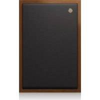
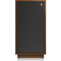
Introduction Thank you for purchasing Tannoy SRM-series monitors. These are professional mid-eld reference monitors which provide unrivaled musical articulation and outstanding dynamics and accuracy. Using advanced dual concentric drivers, they oer the advantages of point source operation in a very cost-eective design. The attractive wood panel cabinet and front panel contribute to their excellent acoustic performance. Due to the point source operation, they will perform equally well in both landscape and portrait orientation. This quick start guide is intended to provide the user with some useful advice on how to install and use the loudspeakers, as well as technical information about how the system is designed and its detailed specications. We hope you get the best results from your monitoring system. Once you have set up your new monitors as described in this document, please register your product online at www.tannoy.com – this does not limit your legal rights. Unpacking To get the speaker out of the carton without damage, open the aps fully and bend them right back. Turn the package upside-down on the oor and lift the carton vertically up to leave the speaker resting on its packing tray. Inspect each speaker for signs of transit damage. In the unlikely event of this having occurred, inform the carrier and the supplier. Keep all the packaging if damage has occurred as this will show evidence of excessive handling force. It is also a good idea to keep the carton for future transportation. Caution These monitors are capable of generating high sound levels over a sustained period of time. Because of their low levels of distortion, it is not always obvious that the sound level is high when working with these monitors. Please be aware that exposure to excessive levels over a sustained period of time can lead to permanent hearing damage. (3) (4) (1) (2) (1) (2) (3) (4) (5) (6) (7) (8) (9) (10)
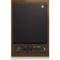
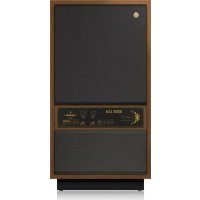
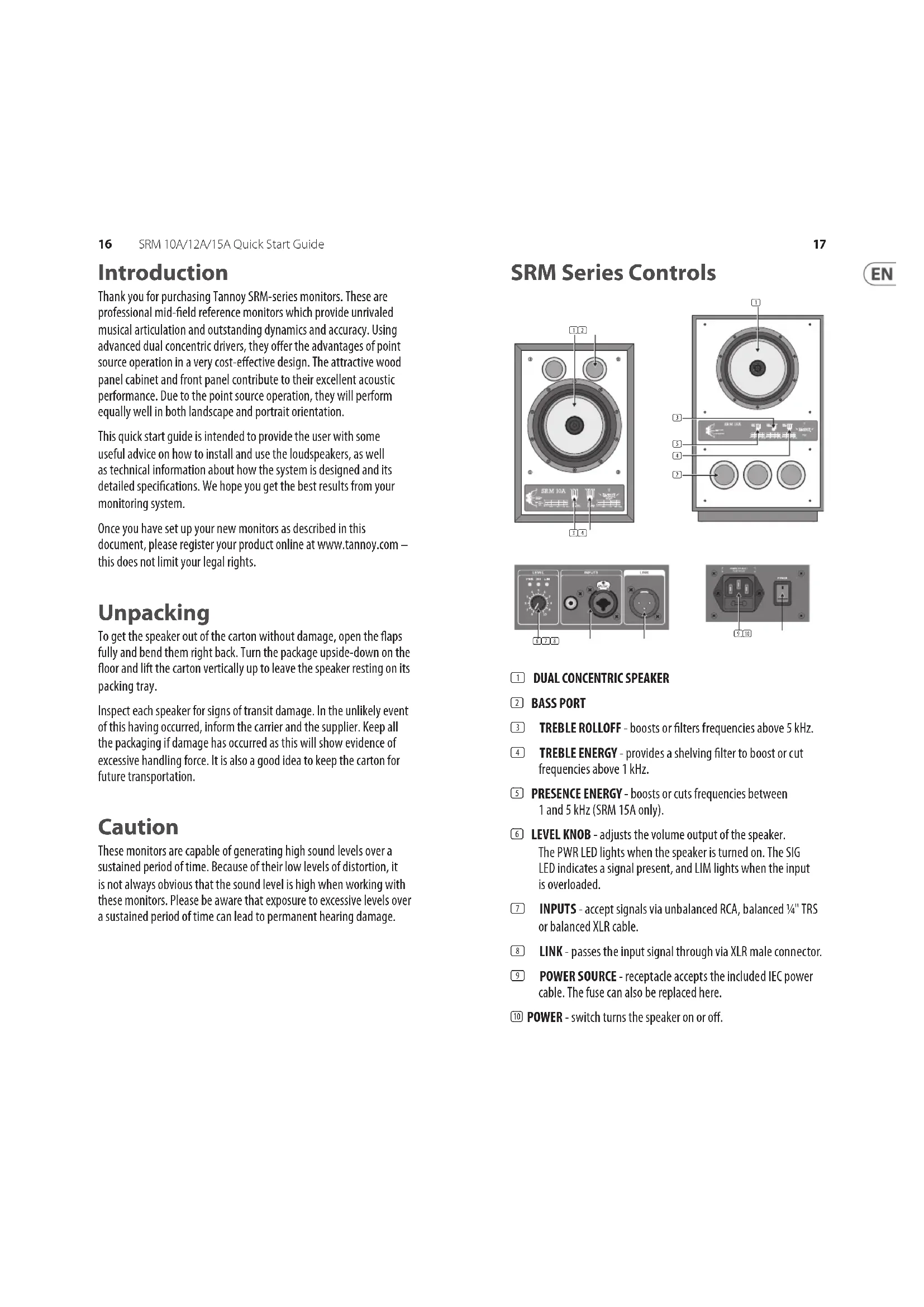
(1) DUAL CONCENTRIC SPEAKER
(2) BASS PORT (3) TREBLE ROLLOFF - boosts or lters frequencies above 5 kHz. (4) TREBLE ENERGY - provides a shelving lter to boost or cut frequencies above 1 kHz. (5) PRESENCE ENERGY - boosts or cuts frequencies between 1 and 5 kHz (SRM 15A only). (6) LEVEL KNOB - adjusts the volume output of the speaker. The PWR LED lights when the speaker is turned on. The SIG LED indicates a signal present, and LIM lights when the input is overloaded. (7) INPUTS - accept signals via unbalanced RCA, balanced ¼" TRS or balanced XLR cable. (8) LINK - passes the input signal through via XLR male connector. (9) POWER SOURCE - receptacle accepts the included IEC power cable. The fuse can also be replaced here. (10) POWER - switch turns the speaker on or o. SRM Series Controls18 SRM 10A/12A/15A Quick Start Guide
Operation Installation When choosing a suitable location for the monitors, bear in mind that the physical mounting of loudspeakers can have a large inuence on performance. For best results, the monitors should be mounted on a rigid structure, supported on pads making contact with the laminated panel. Self-adhesive foam pads are provided with the loudspeakers for that purpose. If you intend to arrange the monitors in landscape format, detach the whole pad from the backing paper and stick it on the large side to become the bottom of the cabinet; for portrait arrangement the pad is pre-cut so that one half can be easily detached to match the smaller size of the bottom panel. We recommend positioning of the monitors so that the drive units are toed inwards, with their axes oriented towards the listening position. The distance between the two speakers should be 2 to 3 metres, depending on the monitoring position. The distance between the monitoring position and each speaker should be slightly greater than the distance between the speakers. If the speakers are placed too close to each other, the full stereo image may not develop. On the other hand, if you place them too far apart you will notice a hole in the middle of the stereo image. Ensure that the console position does not obscure the direct sound radiation from the Dual Concentric drive unit when sitting down. The engineer and producer should have a clear, uninterrupted view of the monitor loudspeakers. Connect the audio signal source (console or interface output) to one of the input connectors on the rear of the speaker. Connections can be made via unbalanced RCA cable, but balanced ¼" TRS or XLR cables are recommended. The ¼"/XLR combo jack is wired as shown: Having chosen an appropriate location for your monitors and arranged them accordingly, connect the power cord to the mains socket and turn the power on. The PWR LED on the rear panel should now be illuminated. XLR Input ¼" TRS Input Signal (+) Pin 2 Tip (T) Signal (-) Pin 3 Ring (R) Ground Pin 1 Screen (S) Adjustment With the LEVEL knob set at the center (12:00) position, slowly raise the output from your console or interface while audio is playing. The green SIG LED should light up whenever audio enters the speakers INPUTS. If the red LIM LED ever lights, reduce the output of your source audio. If more volume is needed, raise the LEVEL knob to an appropriate setting. Each loudspeaker model features two controls labeled Treble Energy and Treble Roll-O, and the SRM 15A has an additional control called Presence Energy. These allow the high frequency response to be tailored to your listening environment. To make adjustments, each speaker should be operated one at a time in mono. Pan the output from your source audio so that the full signal passes only to the left or right speaker. The Treble Energy control increases or decreases the HF driver over its entire frequency range from 1 kHz to 20 kHz, while the Treble Roll-O only aects the highest frequencies above 5 kHz. Presence Energy boosts or cuts frequencies between 1 and 5 kHz. All controls should be set to the ‘Level’ position initially. If the sound is too bright or dull, the Treble Energy can be used for broad adjustments. After this setting has been established, further ne tuning with the Treble Energy (and Presence Energy for the SRM 15A) can be made as necessary. Changes to each control can be fairly subtle and may not be heard at all if the audio being monitored has little energy in the spectrum being adjusted. Keep in mind that speaker positioning and room acoustics also aect a speaker’s response.20 SRM 10A/12A/15A Quick Start Guide
Servicing Cleaning the cabinet To remove marks and scus, use a medium soft brush. If necessary, a little warm water and detergent can be used, but under no circumstances use a solvent or abrasive cleaner. The surface will change colour when wet but will return to normal when dry. Dual Concentric driver removal Before any servicing operation, the amplier should be disconnected from signal input and mains power. Lay the cabinet on its back, taking care to protect the rear plate. Remove the four hexagonal bolts and set aside. Ease the driver from the front of the cabinet, taking care not to mark the front surface. Use a piece of stout cardboard to lever against if necessary. Remove the driver and disconnect the internal wiring, taking care not to damage the moving parts of the LF driver. To ret the driver, connect the cables from the wiring harness to the LF (red +ve and blue -ve) and HF (white +ve and black -ve) terminals. Fit the driver into the mounting hole, fasten the bolts nger tight and then progressively torque them down so that the driver seats evenly. Drive unit servicing The HF unit may be tted with a new diaphragm assembly. With the driver face down, release the three bolts securing the HF assembly and lift the HF unit vertically upwards and away from magnetic attraction caused by the LF magnet. Replace the diaphragm - it is self-centering - taking care to align the parts correctly. To ret the HF unit, hold it about 30 cm vertically above the LF magnet in both hands while resting on your elbows. Slide your elbows apart and lower the HF unit onto the back of the LF magnet. As the HF unit gets close to the magnet you will feel the magnetic elds repelling. Align the xing holes and secure with the bolts, tightening down evenly. Do not tighten the bolts nally until you are sure the HF unit is seated correctly and the two magnet systems appear parallel. The LF unit may be re-coned in the normal way. Use only the parts and adhesive supplied in the re-cone kit. Checking the unit The whole unit can be checked using a sine wave generator connected to the input. A high quality, low distortion (preferably a beat frequency) oscillator will be required to check for any buzz and rattle noise generated by the drive unit. The voltage to be applied at the input should be 0.2 Vrms. Testing the whole unit has an obvious drawback in that, in the case of any defect it may be dicult to determine whether the drive unit or the amplier is faulty. In which case each part would have to be checked independently, meaning that the drive unit should be removed (refer to above). If for whatever reason the amplier needs to be removed from the cabinet, care should be taken to remove only the relevant screws (there are 8 mounting screws, 2 on each side of the plate). Fuse A fuse is located just under the mains input. Replacement is simple and a spare fuse is provided inside the fuse housing itself. Always use the correctly rated fuse, as indicated on the silk screen printing, there are two dierent types according to the operating voltage. Any other servicing regarding the electronic section should be undertaken by qualied and authorised personnel only. In case of any malfunction of the unit, the rst thing to be checked should be the input connection, especially if the source has unbalanced outputs as improper connection can result in signicant level reduction and aect the response.22 SRM 10A/12A/15A Quick Start Guide
System Frequency response 40 Hz – 30 kHz ±6 dB 38 Hz – 30 kHz ±6 dB 35 Hz – 30 kHz ±6 dB Nominal dispersion 90° conical @ -6 dB point 90° conical @ -6 dB point 90° conical @ -6 dB point Maximum SPL 116 dB 121 dB 126 dB Crossover type 2 way, active 2 way, active 2 way, active Crossover frequency 1.2 kHz 1.2 kHz 1.1 kHz Transducers 1 x 10" (254 mm) paper pulp cone with twin roll impregnated fabric surround 2" (52 mm) edge-wound voice coil 1 x 1.3" (33 mm) aluminium/ magnesium alloy dome with edge- wound voice coil 1 x 12" (300 mm) paper pulp cone with twin roll impregnated fabric surround 2" (52 mm) edge-wound voice coil 1 x 1.3" (33 mm) aluminium/ magnesium alloy dome with edge- wound voice coil 1 x 15" (380 mm) paper pulp cone with twin roll impregnated fabric surround 2" (52 mm) edge-wound voice coil 1 x 1.3" (33 mm) aluminium/ magnesium alloy dome with edge-wound voice coil Limiter Independent high and low frequency limiters Independent high and low frequency limiters Independent high and low frequency limiters Magnetic shielding No No Amplier Maximum output power* 600 W 600 W Type LF: Class-D HF: Class AB LF: Class-D HF: Class AB Protection Short circuit, thermal Short circuit, thermal Connectors Inputs 1 x XLR / 1/4" TRS combo jack, balanced / unbalanced 1 x RCA, unbalanced 1 x XLR / 1/4" TRS combo jack, balanced / unbalanced 1 x RCA, unbalanced Sensitivity for max out with Level control at 5 XLR: +4 dBu / RCA: -10 dB V,nominal XLR: +4 dBu / RCA: -10 dB V,nominal Input impedance XLR: 11 kΩ unbalanced / 22 kΩ balanced, RCA: 11 kΩ unbalanced XLR: 11 kΩ unbalanced / 22 kΩ balanced, RCA: 11 kΩ unbalanced Maximum input level +20 dBu +20 dBu Outputs Link: 1 x XLR, balanced Link: 1 x XLR, balanced User controls Power on / o, level, treble roll o, treble energy Power on / o, level, treble roll o, treble energy Power on / o, level, treble roll o, treble energy, presence energy72 SRM 10A/12A/15A Quick Start Guide
Other important information
Please register your new Music Tribe equipment right after you purchase it by visiting tannoy.com. Registering your purchase using our simple online form helps us to process your repair claims more quickly and eciently. Also, read the terms and conditions of our warranty, if applicable.
2. Malfunction. Should your
Music Tribe Authorized Reseller not be located in your vicinity, you may contact the Music Tribe Authorized Fulller for your country listed under “Support” at tannoy. com. Should your country not be listed, please check if your problem can be dealt with by our “Online Support” which may also be found under “Support” at tannoy.com. Alternatively, please submit an online warranty claim at behringer. com BEFORE returning the product.
3. Power Connections.
Before plugging the unit into a power socket, please make sure you are using the correct mains voltage for your particular model. Faulty fuses must be replaced with fuses of the same type and rating without exception.
Other important information
FEDERAL COMMUNICATIONS COMMISSION COMPLIANCE INFORMATION Responsible Party Name: Music Tribe Commercial NV Inc. Address: 122 E. 42nd St.1, 8th Floor NY, NY 10168, United States Email Address: legal@musictribe.com
This equipment has been tested and found to comply with the limits for a Class A digital device, pursuant to part 15 of the FCC Rules. These limits are designed to provide reasonable protection against harmful interference when the equipment is operated in a commercial environment. This equipment generates, uses, and can radiate radio frequency energy and, if not installed and used in accordance with the instruction manual, may cause harmful interference to radio communications. Operation of this equipment in a residential area is likely to cause harmful interference in which case the user will be required to correct the interference at his own expense. This equipment complies with Part 15 of the FCC Rules. Operation is subject to the following two conditions: (1) This device may not cause harmful interference, and (2) This device must accept any interference received, including interference that may cause undesired operation.
Operation of this equipment in a residential environment could cause radio interference. Hereby, Music Tribe declares that this product is in compliance with Directive 2014/35/EU,Directive 2014/30/ EU, Directive 2011/65/EU and Amendment 2015/863/EU, Directive 2012/19/EU, Regulation 519/2012 REACH SVHC and Directive 1907/2006/EC. Full text of EU DoC is available at https://community.musictribe.com/ EU Representative: Music Tribe Brands DK A/S Address: Gammel Strand 44, DK-1202 København K, Denmark UK Representative: Music Tribe Brands UK Ltd. Address: 6 Lloyds Avenue, Unit 4CL London EC3N 3AX, United Kingdom