
MF3580 - Sewing machine JUKI - Free user manual and instructions
Find the device manual for free MF3580 JUKI in PDF.
| Product Type | Industrial double chain stitch sewing machine (401 LSc-3) |
| Number of needles | 3 |
| Number of threads | 6 |
| Applications | Denim, workwear, felt |
| Maximum sewing speed | 4,500 stitches/min |
| Recommended sewing speed | 3,500 stitches/min |
| Needle spacing | 8 mm (3.2 mm between needles, total width 6.4 mm) |
| Stitch length | 2.1 to 3.6 mm (standard 3.2 mm) |
| Needle type | UY130GS (standard), No. 140 (#22) |
| Needle bar stroke | 33 mm |
| Head dimensions | 420 × 285 × 345 mm |
| Head weight | 23.5 kg |
| Presser foot lift height | 9 mm max (standard 6.5 mm) |
| Lubrication | Automatic rotary pump, JUKI MACHINE OIL No. 18 |
| Oil tank capacity | 140 ml |
| Operating temperature | 5 to 35 °C |
| Operating humidity | 35 to 85% (non-condensing) |
| Power supply | Single phase, 50/60 Hz, rated voltage ±10% |
| Sound level at workstation | 80 dB(A) (ISO 10821, at 3,500 sti/min) |
| Maintenance and cleaning | Regular cleaning of oil filter, oil drain and refill, manual lubrication of joints every 3 months |
| Safety | Belt guard, needle cover, emergency stop, mandatory grounding |
| Spare parts and repairability | Original JUKI parts, maintenance by qualified technician |
Frequently Asked Questions - MF3580 JUKI
User questions about MF3580 JUKI
0 question about this device. Answer the ones you know or ask your own.
Ask a new question about this device
Download the instructions for your Sewing machine in PDF format for free! Find your manual MF3580 - JUKI and take your electronic device back in hand. On this page are published all the documents necessary for the use of your device. MF3580 by JUKI.
USER MANUAL MF3580 JUKI
natural_image
Technical line drawing of a Juki sewing machine (no text or symbols present)| 注意:このたびは、当社の製品をお買い上げいただきましてありがとうございました。安全に使用していただくために、使用前に必ずこの取扱説明書をお読みください。また、いつでもすぐに読めるように、この取扱説明書を保管してください。 |
| NOTE:Read safety instructions carefully and understand them before using.Retain this Instruction Manual for future reference. |
| HINWEIS:Lesen Sie die Sicherheitsanweisungen aufmerksam durch, um sich mit ihnen vertraut zu machen, bevor Sie diese Maschine in Betrieb nehmen. Bewahren Sie diese Bedienungsanleitung für spätere Bezugnahme auf. |
| NOTE:Avant d’utiliser la machine, lire attentivement toutes les consignes de sécurité.Conserver ce manuel pour pouvior le consulter en cas de besoin. |
| NOTA:Antes de comenzar a usar esta máquina lea con detención hasta comprender todas las instrucciones de seguridad. Conserve este Manual de instrucciones a mano para futuras consultas. |
| NOTA:Leggere attentamente e compredere tutte le istruzioni per la sicurezza prima di inziare l’uso di questa macchina. Conservare questo Manuale d’Instruzioni per pronto riferimento. |
| 注意:为了安全地使用,请您在使用之前一定阅读本使用说明书。另外,请您注意保管本使用说明书,以便随时查阅。 |
日本語
安全にご使用していただくために
natural_image
Line drawing of hands holding a handheld electronic device with no visible text or symbols
natural_image
Technical line drawing of a mechanical assembly with hands operating a tool (no text or symbols)

natural_image
Technical line drawing of a mechanical component with concentric rings and mounting holes (no text or symbols)
5. 糸切りメスの取り付け方
注意
natural_image
Technical line drawing of a sewing machine with no visible text or symbols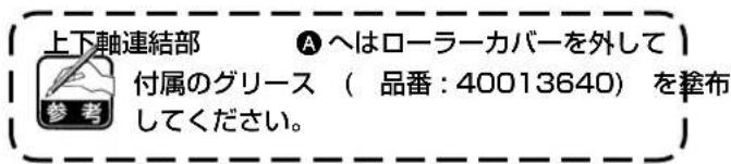
natural_image
Technical line drawing of a mechanical assembly with gears and shafts (no text or symbols)natural_image
Technical line drawing of a mechanical assembly with no visible text or symbolsルーパーが倒れた状態


natural_image
Technical line drawing of a mechanical assembly with spring and mounting bracket (no text or symbols)
natural_image
Technical line drawing of a hand operating a mechanical component with a labeled arrow (B), no readable text or symbols present.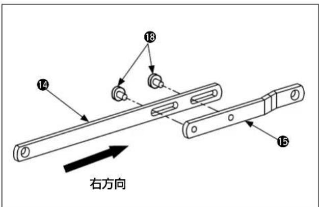
差動なし
(2) 差動送り量の調整
natural_image
Technical line drawing of a mechanical assembly with gears and shaft (no text or symbols)(1) 上送りローラー引き量の調整
natural_image
Technical line drawing of a mechanical assembly with no visible text or symbolsnatural_image
Technical line drawing of a mechanical assembly with no visible text or symbolsnatural_image
Technical line drawing of a mechanical clamp or bracket assembly (no text or symbols)natural_image
Technical line drawing of a mechanical assembly with bolts and a clamp (no text or symbols)natural_image
Mechanical assembly diagram showing a rotating component with a directional arrow indicating motion (no text or symbols present)natural_image
Technical line drawing of a mechanical device with no visible text or symbols頭部右側面
圧力調節板バネ関係

頭部左側面
ゲージ関係部分(差動あり機構)

ゲージ関係部分(差動なし機構)
(6) 主送り歯・差動送り歯の調整方法

(2) フォルダーの取り付け位置の調整
natural_image
Technical line drawing of a mechanical assembly with no visible text or symbols※ この作業は、
TO ENSURE SAFE USE OF YOUR SEWING MACHINE
For the sewing machine, automatic machine and ancillary devices (hereinafter collectively referred to as "machine"), it is inevitable to conduct sewing work near moving parts of the machine. This means that there is always a possibility of unintentionally coming in contact with the moving parts. Operators who actually operate the machine and maintenance personnel who are involved in maintenance and repair of the machine are strongly recommended to carefully read to fully understand the following SAFETY PRECAUTIONS before using/maintaining the machine. The content of the SAFETY PRECAUTIONS includes items which are not contained in the specifications of your product.
The risk indications are classified into the following three different categories to help understand the meaning of the labels. Be sure to fully understand the following description and strictly observe the instructions.
( I ) Explanation of risk levels
 | DANGER:This indication is given where there is an immediate danger of death or serous injury if the person in charge or any third party mishandles the machine or does not avoid the dangerous situation when operating or maintaining the machine. |
 | WARNING:This indication is given where there is a potentiality for death or serious injury if the person in charge or any third party mishandles the machine or does not avoid the dangerous situation when operating or maintaining the machine. |
 | CAUTION:This indication is given where there is a danger of medium to minor injury if the person in charge or any third party mishandles the machine or does not avoid the dangerous situation when operating or maintaining the machine. |
 | Items requiring special attention. |
(II) Explanation of pictorial warning indications and warning labels
| Pictorial warning indication |  | There is a risk of injury if contact-ing a moving section. | Pictorial warning indication | Be aware that holding the sewing machine during operation can hurt your hands. | |
 | There is a risk of electrical shock if contacting a high-voltage section. | There is a risk of entanglement in the belt resulting in injury. | |||
 | There is a risk of a burn if contact-ing a high-temperature section. | There is a risk of injury if you touch the button carrier. | |||
 | Be aware that eye deficiency can be caused by looking directly at the laser beam. | Indication label | The correct direction is indicated. | ||
 | There is a risk of contact between your head and the sewing ma-chine. | Connection of a earth cable is indicated. |


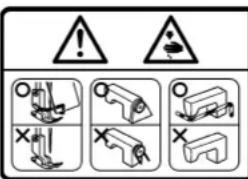
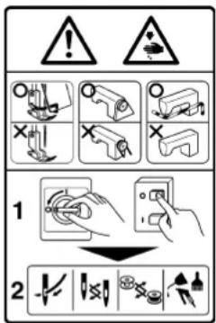


There is the possibility that slight to serious injury or death may be caused. There is the possibility that injury may be caused by touching moving part.
② · To perform sewing work with safety guard.
• To perform sewing work with safety cover.
- To perform sewing work with safety protection device.
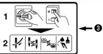
③ • Be sure to turn the power OFF before carrying out "machine-head threading", "needle changing", "bobbin changing" or "oiling and cleaning".


Hazardous voltage will cause injury. Turn off main switch and unplug power cord and wait at least 5 minutes before opening this cover.

DANGER
- When it is necessary to open the control box containing electrical parts, be sure to turn the power off and wait for five minutes or more before opening the cover in order to prevent accident leading to electrical shock.

CAUTION
Basic precaution
- Be sure to read the instruction manual and other explanatory documents supplied with accessories of the machine before using the machine. Carefully keep the instruction manual and the explanatory documents at hand for quick reference.
- The content of this section includes items which are not contained in the specifications of your product.
- Be sure to wear safety goggles to protect against accident caused by needle breakage.
- Those who use a heart pacer have to use the machine after consultation with a medical specialist.
Safety devices and warning labels
- Be sure to operate the machine after verifying that safety device(s) is correctly installed in place and works normally in order to prevent accident caused by lack of the device(s).
- If any of the safety devices is removed, be sure to replace it and verify that it works normally in order to prevent accident that can result in personal injury or death.
- Be sure to keep the warning labels adhered on the machine clearly visible in order to prevent accident that can result in personal injury or death. If any of the labels has stained or come unstuck, be sure to change it with a new one.
Application and modification
- Never use the machine for any application other than its intended one and in any manner other than that prescribed in the instruction manual in order to prevent accident that can result in personal injury or death. JUKI assumes no responsibility for damages or personal injury or death resulting from the use of the machine for any application other than the intended one.
- Never modify and alter the machine in order to prevent accident that can result in personal injury or death. JUKI assumes no responsibility for damages or personal injury or death resulting from the machine which has been modified or altered.
Education and training
- In order to prevent accident resulting from unfamiliarity with the machine, the machine has to be used only by the operator who has been trained/educated by the employer with respect to the machine operation and how to operate the machine with safety to acquire adequate knowledge and operation skill. To ensure the above, the employer has to establish an education/training plan for the operators and educate/train them beforehand.
Items for which the power to the machine has to be turned off
Turning the power off: Turning the power switch off, then removing the power plug from the outlet. This applies to the following.
- Be sure to immediately turn the power off if any abnormality or failure is found or in the case of power failure in order to protect against accident that can result in personal injury or death.
- To protect against accident resulting from abrupt start of the machine, be sure to carry out the following operations after turning the power off. For the machine incorporating a clutch motor, in particular, be sure to carry out the following operations after turning the power off and verifying that the machine stops completely.
2-1. For example, threading the parts such as the needle, looper, spreader etc. which have to be threaded, or changing the bobbin.
2-2. For example, changing or adjusting all component parts of the machine.
2-3. For example, when inspecting, repairing or cleaning the machine or leaving the machine. - Be sure to remove the power plug by holding the plug section instead of the cord section in order to prevent electrical-shock, earth-leakage or fire accident.
- Be sure to turn the power off whenever the machine is left unattended between works.
- Be sure to turn the power off in the case of power failure in order to prevent accident resulting of breakage of electrical components.
PRECAUTIONS TO BE TAKEN IN VARIOUS OPERATION STAGES
Transportation
- Be sure to lift and move the machine in a safe manner taking the machine weight in consideration. Refer to the text of the instruction manual for the mass of the machine.
- Be sure to take sufficient safety measures to prevent falling or dropping before lifting or moving the machine in order to protect against accident that can result in personal injury or death.
- Once the machine has been unpacked, never re-pack it for transportation to protect the machine against breakage resulting from unexpected accident or dropping.
Unpacking
- Be sure to unpack the machine in the prescribed order in order to prevent accident that can result in personal injury or death. In the case the machine is crated, in particular, be sure to carefully check nails. The nails have to be removed.
- Be sure to check the machine for the position of its center of gravity and take it out from the package carefully in order to prevent accident that can result in personal injury or death.
Installation
(I) Table and table stand
- Be sure to use JUKI genuine table and table stand in order to prevent accident that can result in personal injury or death. If it is inevitable to use a table and table stand which are not JUKI genuine ones, select the table and table stand which are able to support the machine weight and reaction force during operation.
- If casters are fitted to the table stand, be sure to use the casters with a locking mechanism and lock them to secure the machine during the operation, maintenance, inspection and repair in order to prevent accident that can result in personal injury or death.
(II) Cable and wiring
- Be sure to prevent an extra force from being applied to the cable during the use in order to prevent electrical-shock, earth-leakage or fire accident. In addition, if it is necessary to cable near the operating section such as the V-belt, be sure to provide a space of 30 mm or more between the operating section and the cable.
- Be sure to avoid starburst connection in order to prevent electrical-shock, earth-leakage or fire accident.
- Be sure to securely connect the connectors in order to prevent electrical-shock, earth-leakage or fire accident. In addition, be sure to remove the connector while holding its connector section.
(III) Grounding
- Be sure to have an electrical expert install an appropriate power plug in order to prevent accident caused by earth-leakage or dielectric strength voltage fault. In addition, be sure to connect the power plug to the grounded outlet without exceptions.
- Be sure to ground the earth cable in order to prevent accident caused by earth leakage.
(IV) Motor
- Be sure to use the specified rated motor (JUKI genuine product) in order to prevent accident caused by burnout.
- If a commercially available clutch motor is used with the machine, be sure to select one with an entanglement preventive pulley cover in order to protect against being entangled by the V-belt.
Before operation
- Be sure to make sure that the connectors and cables are free from damage, dropout and looseness before turning the power on in order to prevent accident resulting in personal injury or death.
- Never put your hand into the moving sections of the machine in order to prevent accident that can result in personal injury or death. In addition, check to be sure that the direction of rotation of the pulley agrees with the arrow shown on pulley.
- If the table stand with casters is used, be sure to secure the table stand by locking the casters or with adjusters, if provided, in order to protect against accident caused by abrupt start of the machine.
During operation
- Be sure not to put your fingers, hair or clothing close to the moving sections such as the handwheel, hand pulley and motor or place something near those sections while the machine is in operation in order to prevent accident caused by entanglement that can result in personal injury or death.
- Be sure not to place your fingers near the surround area of the needle or inside the thread take-up lever cover when turning the power on or while the machine is in operation in order to prevent accident that can result in personal injury or death.
- The machine runs at a high speed. Never bring your hands near the moving sections such as looper, spreader, needle bar, hook and cloth trimming knife during operation in order to protect your hands against injury. In addition, be sure to turn the power off and check to be sure that the machine completely stops before changing the thread.
-
Be careful not to allow your fingers or any other parts of your body to be caught between the machine and table when removing the machine from or replacing it on the table in order to prevent accident that can result in personal injury or death.
-
Be sure to turn the power off and check to be sure that the machine and motor completely stop before removing the belt cover and V-belt in order to prevent accident caused by abrupt start of the machine or motor.
- If a servomotor is used with the machine, the motor does not produce noise while the machine is at rest. Be sure not to forget to turn the power off in order to prevent accident caused by abrupt start of the motor.
- Never use the machine with the cooling opening of the motor power box shielded in order to prevent fire accident by overheat.
Lubrication
- Be sure to use JUKI genuine oil and JUKI genuine grease to the parts to be lubricated.
- If the oil adheres on your eye or body, be sure to immediately wash it off in order to prevent inflammation or irritation.
- If the oil is swallowed unintentionally, be sure to immediately consult a medical doctor in order to prevent diarrhea or vomiting.
Maintenance
- In prevention of accident caused by unfamiliarity with the machine, repair and adjustment has to be carried out by a service technician who is thoroughly familiar with the machine within the scope defined in the instruction manual. Be sure to use JUKI genuine parts when replacing any of the machine parts. JUKI assumes no responsibility for any accident caused by improper repair or adjustment or the use of any part other than JUKI genuine one.
- In prevention of accident caused by unfamiliarity with the machine or electrical-shock accident, be sure to ask an electrical technician of your company or JUKI or distributor in your area for repair and maintenance (including wiring) of electrical components.
- When carrying out repair or maintenance of the machine which uses air-driven parts such as an air cylinder, be sure to remove the air supply pipe to expel air remaining in the machine beforehand, in order to prevent accident caused by abrupt start of the air-driven parts.
- Be sure to check that screws and nuts are free from looseness after completion of repair, adjustment and part replacement.
- Be sure to periodically clean up the machine during its duration of use. Be sure to turn the power off and verify that the machine and motor stop completely before cleaning the machine in order to prevent accident caused by abrupt start of the machine or motor.
- Be sure to turn the power off and verify that the machine and motor stop completely before carrying out maintenance, inspection or repair of the machine. (For the machine with a clutch motor, the motor will keep running for a while by inertia even after turning the power off. So, be careful.)
- If the machine cannot be normally operated after repair or adjustment, immediately stop operation and contact JUKI or the distributor in your area for repair in order to prevent accident that can result in personal injury or death.
- If the fuse has blown, be sure to turn the power off and eliminate the cause of blowing of the fuse and replace the blown fuse with a new one in order to prevent accident that can result in personal injury or death.
- Be sure to periodically clean up the air vent of the fan and inspect the area around the wiring in order to prevent fire accident of the motor.
Operating environment
- Be sure to use the machine under the environment which is not affected by strong noise source (electromagnetic waves) such as a high-frequency welder in order to prevent accident caused by malfunction of the machine.
- Never operate the machine in any place where the voltage fluctuates by more than "rated voltage ± 10% in order to prevent accident caused by malfunction of the machine.
- Be sure to verify that the air-driven device such as an air cylinder operates at the specified air pressure before using it in order to prevent accident caused by malfunction of the machine.
- To use the machine with safety, be sure to use it under the environment which satisfies the following conditions:
Ambient temperature during operation 5°C to 35°C
Relative humidity during operation 35 % to 85 %
- Dew condensation can occur if bringing the machine suddenly from a cold environment to a warm one. So, be sure to turn the power on after having waited for a sufficient period of time until there is no sign of water droplet in order to prevent accident caused by breakage or malfunction of the electrical components.
- Be sure to stop operation when lightning flashes for the sake of safety and remove the power plug in order to prevent accident caused by breakage or malfunction of the electrical components.
- Depending on the radio wave signal condition, the machine may generate noise in the TV or radio. If this occurs, use the TV or radio with kept well away from the machine.
- In order to ensure the work environment, local laws and regulations in the country where the sewing machine is installed shall be followed. In the case the noise control is necessary, an ear protector or other protective gear should be worn according to the applicable laws and regulations.
- Disposal of products and packages and treatment of used lubricating oil should be carried out properly according to the relevant laws of the country in which the sewing machine is used.
Precautions to be taken so as to use the MS-3580 Series more safely
| 1. To prevent accidents caused by electric shock, never open the motor control box cover or touch the components inside the control box while the power switch is ON. | |
| 1. Never bring your fingers under the needle when the power switch is turned ON or the machine is in operation.2. Never bring your fingers, hair or clothes close to the handwheel and needle or place anything on the handwheel and under the needle while the machine is in operation.3. Loudness and quality of sound will change by kind and shape of the sewing product including sewing speed, and sewing conditions by number of overlapped pieces, stitch length, etc.When using the sewing machine for a long period of time, there is a case where a sense of disharmony is felt sometimes. At this time, operate the sewing machine with your ears stopped by earmuffs or the like.4. Be sure to turn OFF the power and perform the work after ascertaining that the sewing machine does not run even when the starting pedal is depressed in case of checking, adjusting, cleaning, threading or replacing the needle of the sewing machine.5. Never operate the sewing machine with the ground wire for the power supply removed so as to ensure safety.6. Be sure to turn OFF the power switch in advance in case of inserting/removing the power plug.7. In time of thunder and lightning, stop your work and disconnect the power plug from the receptacle so as to ensure safety.8. When you move the sewing machine from a cold place directly to a warm place, dew condensation may result. Turn ON the power to the machine after you have confirmed that there is no fear of dew condensation.9. In case of maintenance, inspection, or repair, be sure to turn OFF the power switch and confirm that the sewing machine and the motor have completely stopped before starting the work. (In case of the clutch motor, it continues rotating for a while by the inertia even after turning OFF the power switch. So, be careful.)10. Be careful of handling this product so as not to pour water or oil, shock by dropping, and the like since this product is a precision instrument. |

CAUTION
In addition, be aware that the safety devices such as the "eye protection cover" and "finger guard" are sometimes omitted in the sketches, illustrations and figures included in the Instruction Manual for the explanation's sake. In the practical use, never remove those safety devices.
DECLARATION OF INCORPORATION OF PARTLY COMPLETED MACHINERY
We hereby declare that the sewing machine (sewing head) described below ;
- Must not be put into service until the machinery to which it is incorporated has been declared in conformity with the provisions of the Directive 2006/42/EC, and
- Conforms to the essential requirements of the Directive 2006/42/EC, described in the technical documentation, and
- To be prepared with the above technical documentation compiled in accordance with part B of Annex VII, and
- Also to conform to the RoHS Directive 2011/65/EU
- Relevant information on which should be transmitted in response to a reasoned request by the national authorities, by the electronic method or other according to the request.
Model
MS-3580 Series
Description Industrial Sewing Machine
Function make stitches and sew
Applied harmonized standards, in particular :
EN ISO12100, EN ISO10821, EN 50581
Manufacturer :
JUKI CORPORATION
2-11-1, Tsurumaki, Tama-shi, Tokyo, Japan
CONTENTS
I. SPECIFICATIONS....1
II. INSTALLATION 2
- Installing the machine head .... 2
- Installing the belt cover (only for the sewing machine provided with a clutch motor)....3
- Relation between the motor pulley and the belt (only for the sewing machine provided with a clutch motor)......4
- Installing the presser lifting lever 5
- Installing the thread trimming knife....5
- Installing the cloth puller cover 6
- Installing the handwheel 6
- Installing the thread stand....6
- Installing procedure of the thread take-up lever oil guard 7
III. PREPARATION AND OPERATION 8
- Names of machine head ....8
- Lubrication....9
- Checking the direction of rotation 12
- Attaching the needles 12
- How to pass the threads....13
- Presser adjustment 16
- Adjustment of feed mechanisms .... 18
- Adjustment of drawing amount of upper feed roller 19
IV. STANDARD ADJUSTMENT 22
- How to remove the gauge components and upper feed roller (mechanism with differential feed and mechanism without differential feed)....22
- Timing between the looper and needle bar....24
- Adjustment of the needle entry positions in the right-left and front-rear directions .....26
- Looper adjustment 27
- Adjusting the height of the needle bar 29
- Adjustment of the looper motion paths....30
- Adjustment of rear needle guard 32
- Adjustment of feed dog height and longitudinal movement (mechanism with differential feed) 33
- Adjustment of feed dog height and longitudinal movement (mechanism without differential feed)....35
- Adjustment of upper feed roller 38
- Adjustment of needle thread path....40
- Adjustment of looper thread cam 42
- Adjustment of tension disk floating....43
- Adjustment of folder....44
- Cleaning the sewing machine head....46
V. TROUBLES AND CORRECTIVE MEASURES 47
VI. DRAWING OF THE TABLE ....53
VII. TABLE MACHINING DIAGRAM (only for the sewing machine provided with a clutch motor) 54
I. SPECIFICATIONS
Roller mechanism/clutch type
| No. | Model Specifications | ||
| Item MS-3580SF/1SN | MS-3580SF/0SN | ||
| 1 Stitch type 3-needle, 6-thread, double chainstitch machine (401 LSc-3) | |||
| 2 Application Denim, working clothes, felt, etc. | |||
| 3 Max. sewing speed 4,500 sti/min | |||
| 4 Sewing speed 3,500 sti/min | |||
| 5 Needle gauge 8 gauge: 3.2 mm, total width: 6.4 mm | |||
| 6 Stitch length 2.1 to 3.6 mm (standard : 3.2 mm) at 1-inch intervals | |||
| 7 | Needle(standard size) | UY130GS (standard) | |
| 140 (#22) | |||
| 8 Needle bar stroke 33mm | |||
| 9 Number of threads 6 pcs. | |||
| 10 External dimensions H : 420 x W : 285 x D : 345 mm | |||
| 11 Machine head weight | 23.5kg | ||
| 12 Lifting amount of presser | Max. 9 mm (At the time of delivery from factory : 6.5 mm) | ||
| 13 Feed roller width | 11.9mm | ||
| 14 Feed roller shape | Standard (narrow type) | ||
| 15 | Feed adjustment | Main feed : Slide type stitch pitch adjusting system | |
| With differential feed lever adjusting system | Without differential feed | ||
| 16 | Lubrication | Automatic rotary pump lubrication system | |
| 17 | Lubricating oil | JUKI MACHINE OIL No. 18 | |
| 18 | Oil tank capacity | Tank capacity : 140 ml | |
| 19 | Installation | Table and auxiliary drive type | |
| 20 | Working temperature/humidity ranges | Temperature : 5 - 35°C, humidity: 35 - 85% (No dew condensation permissible) | |
| 21 | Supply voltage/frequency | Rated voltage ±10%, 50/60Hz | |
| 22 | Noise | - Equivalent continuous emission sound pressure level (LpA) at the workstation:A-weighted value of 80.0 dB; (Includes KpA = 2.5 dB); according to ISO 10821-C.6.2-ISO 11204 GR2 at 3,500 sti/min. | |
II. INSTALLATION

WARNING :
Be sure to perform the installation work of the machine head with two persons or more.
1. Installing the machine head
At the beginning, the procedure of pulling out the machine head after opening the package is explained.
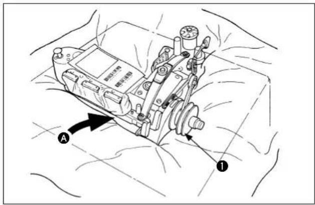
1) There is a gap Ⓐ under the center of the frame. Put there one of your hands and support the machine head.
Next, hold handwheel ① with the other hand.
natural_image
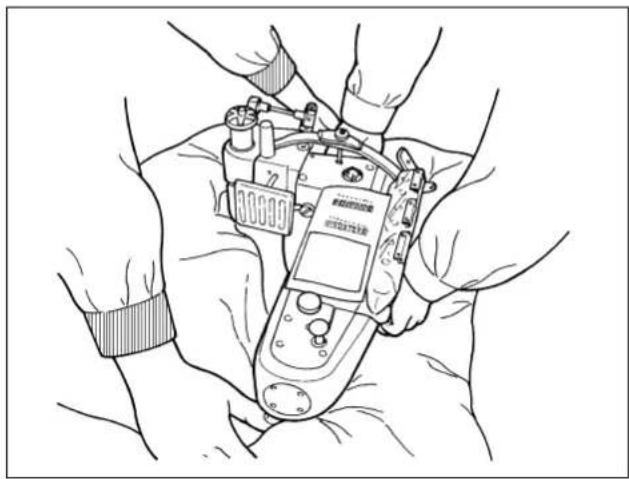
Line drawing of hands holding a device with no visible text or symbols2) Pull out the machine head while another worker is pressing the packing material.
Next, the procedure of installing the machine head is explained.
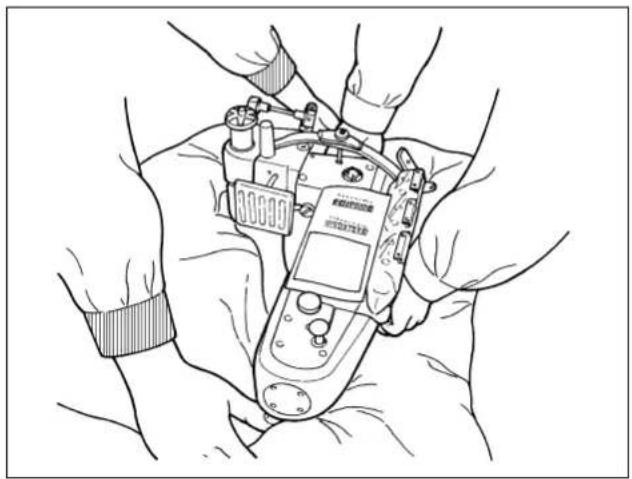
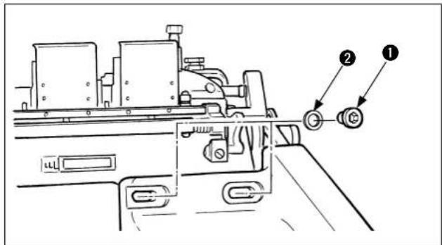
Fix the machine head with head fi xing screw ^① and washer ^② by two persons or more as shown in Fig. 1. In addition, tightening torque of head fi xing screw ^① is 12 to 15 N·m.

natural_image
Technical line drawing of a mechanical assembly with hands operating a tool (no text or symbols present)The work of installing/removing the machine head is accompanied with the danger of the fall of machine head.
Be sure to use the exclusive lift or execute

the work with two persons or more and do not take the hands off until the head fi xing screw is securely tightened.
In addition, when tightening the fi xing screw, laterally adjust the head position so that V-belt is set straight.
If the V-belt is set bent, the progress of abrasion of V-belt is increased.
2. Installing the belt cover (only for the sewing machine provided with a clutch motor)
When your machine uses a clutch motor, it is necessary to firstly mount the belt cover supplied with the unit over the motor to ensure safety. The supplied belt cover is intended for separately-available JUKI's exclusive mount base. If you use a different mount base, a belt cover specific to that mount base should be attached. If your mount base is not provided with its exclusive belt cover as an accessory, please contact the distributor or the manufacturer of your mount base to get a belt cover specific to your mount base.

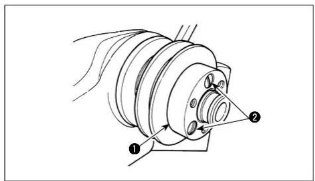
1) Attach spac① with three setscrews ②.
2) Place V-belt ④ in belt cover ③.

natural_image
Technical line drawing of a mechanical component with concentric rings and mounting holes (no text or symbols)3) Pass belt cover ③ through the sewing machine pulley. Put V-belt④ on the pulley. Refer to "Ⅱ-7. Installing the handwheel" for further information on the handwheel.
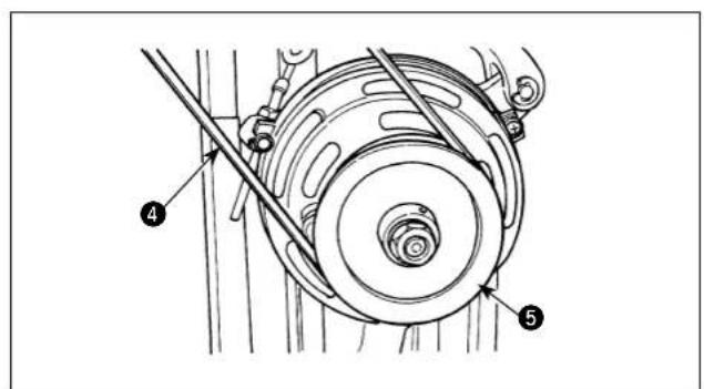
4) Put V-be onto pulley 5 of the clutch motor.
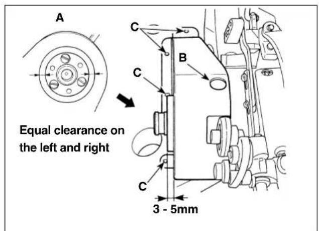
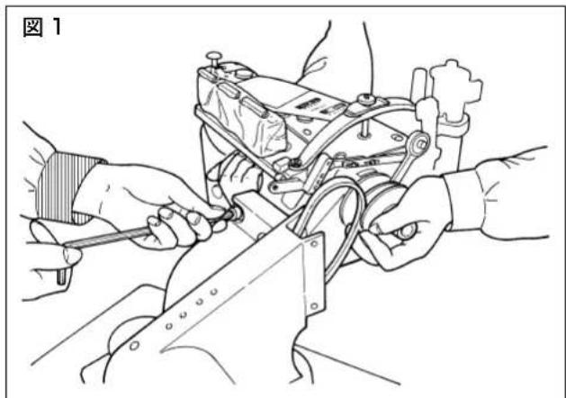
5) Adjust the lateral position of belt cover ③ using the projecting amount, 3 to 5 mm, of spacer ① as a guide. Adjust the longitudinal position of the cover so that the clearance provided between the rim of spacer ① and belt cover ③ is uniform on the right and left sides (A). Once the belt cover is correctly positioned, fi x the belt cover on the table by tightening four washers and four wood screws in the hole C in the belt cover.
6) Fit plug in section B. This hole is used as the oil hole for the connecting rod asm. (40068581).
3. Relation between the motor pulley and the belt (only for the sewing machine provided with a clutch motor)
1) Use a clutch motor with output power of 400 W or more. Use the M-type V-belt.
2) The relation of the motor pulley, belt length and number of revolutions of the machine is as shown in the following table.
| Outside diameter of motor pulley | JUKI part No. of motor pulley | Number of revolutions (sti/min) | Belt length (inch) | JUKI part No. of V-belt | |
| 50Hz 60Hz | 50" MTJVM005000 | 00 | |||
| 110 mm MTKP0105000 | 4420 | ||||
| 105 mm MTKP0100000 | 4210 | ||||
| 100 mm MTKP0095000 | 4000 | ||||
| 95 mm MTKP0090000 | 3790 | ||||
| 90 mm MTKP0085000 | 3580 4320 | 49" MTJVM004900 | 00 | ||
| 85 mm MTKP0080000 | 3370 4070 | ||||
| 80 mm MTKP0075000 | 3160 3810 | ||||
| 75 mm MTKP0070000 | 2950 3560 | ||||
| 70 mm MTKP0065000 | 2740 3300 | ||||
* The effective diameter of the motor pulley is obtained by subtracting 5 mm from the outside diameter.
* The direction of rotation of the motor is counterclockwise as observed from the pulley side. Take care not to allow the motor to rotate in the reverse direction.
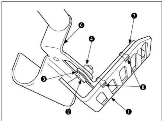
4. Installing the presser lifting lever
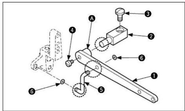
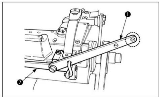
At the beginning, insert boss section A of presser lifting lever 1 into bracket 2. In this state, fi x it on thread tension base 7 with setscrew 3.
Next, pass connecting link ⑤ as shown in the figure and insert O-ring ⑥ into the both ends of it. Finally, fi x it with setscrew ④.
Apply the grease (Part No.: 40013640)

supplied with the unit to the sliding parts encircled with (four locations) at least once every three months.
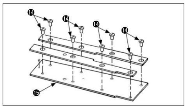
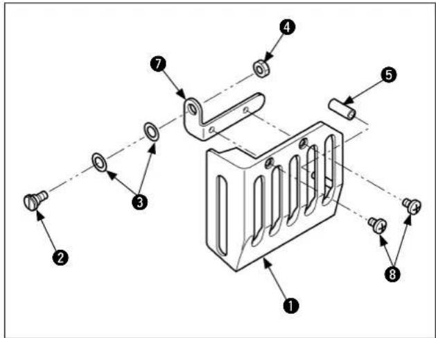
5. Installing the thread trimming knife

CAUTION :
- Turn OFF the power before starting the work so as to prevent accidents caused by abrupt start of the sewing machine.
- Do not touch your fingers or hands to the blade section of knife. so as to prevent fatal accidents.
- Perform the adjustment work by the maintenance engineers who are familiar with the sewing machine and trained for the safety so as to prevent accidents caused by unfamiliarity or wrong adjustment.
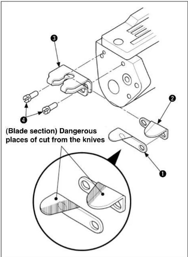
Put bottom thread trimming knife ① on top thread trimming knife ②, insert them into knife cover ③, and install them with two screws ④ as shown in the figure.

stalling the knives, perform the work while taking care of the cut of fingers.
6. Installing the cloth puller cover
• Install top feed cloth puller cover ② with two setscrews ① supplied with the machine as accessories.
- Tightening torque of the screw is 2.5 to 3 N·m.
Turning the sewing machine by hand, per-

form positioning of the cover so that the cover does not come in contact with the sewing machine.
7. Installing the handwheel
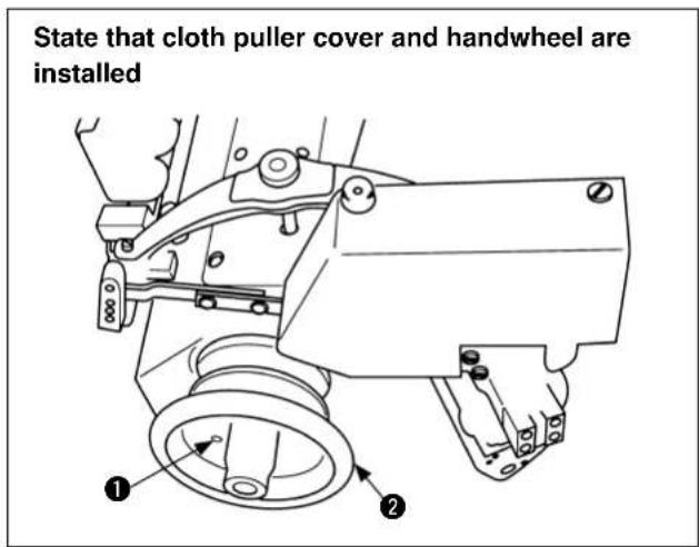
• Install handwh with three setscrews ① supplied with the machine as accessories. (It is not necessary when MT03 is installed.)
- Tightening torque of the screw is 2.5 to 3 N·m.
8. Installing the thread stand
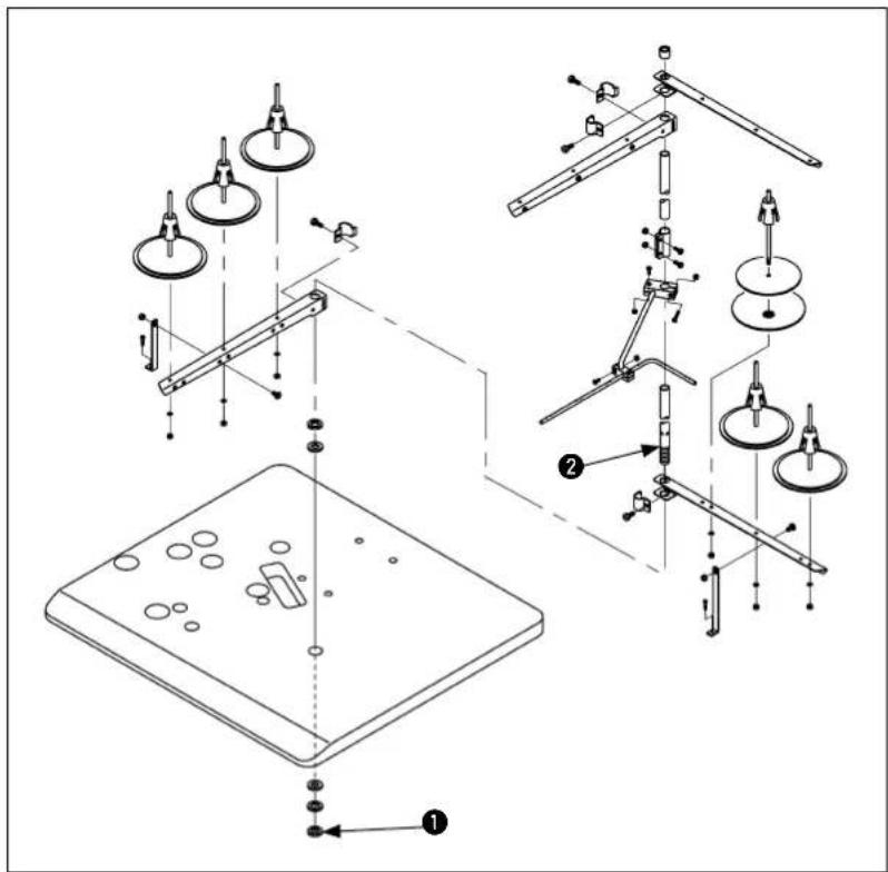
1) Assemble the thread stand as shown in the figure and install it in the hole of the table.
2) Tighten nu to such an extent that the thread stand does not move.
3) When using power supplied by the overhead power line, pass the power supply cord through thread stand ②.
9. Installing procedure of the thread take-up lever oil guard
Attachments for the thread take-up lever oil guard are as shown in the left-hand figure.
Take them out from the accessory box.
① Thread take-up lever oil guard
② Hinge screw
Wave washer
4 Hexagon nut
⑤ Tube hose
⑦ Thread take-up lever oil guard base
⑧ Screws for the thread take-up lever oil guard
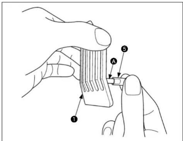
First, insert tube hose ⑤ into protrusion A of thread take-up lever oil guard ① until it goes no further.
Be careful not to forcibly insert the tube hose since it may break.
Then, install the aforementioned thread take-up lever oil guard ① on puller drive cover ⑥ on the machine head side as illustrated in the figure at left.
Firstly, fi x thread take-up lever oil guard base with hinge screw ② and wave washer ③. Secondly, fi x thread take-up lever oil guard ① on thread take-up lever oil guard base with screws ⑧.
At this time, check to be sure that thread take-up lever oil guard ① can be smoothly opened/closed.
Finally, fi x hexagon nut ^4 to prevent the hinge screw from loosening.
Tightening torque is 0.5 to 1.0 N·m as the standard.
III. PREPARATION AND OPERATION
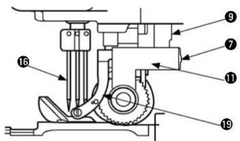
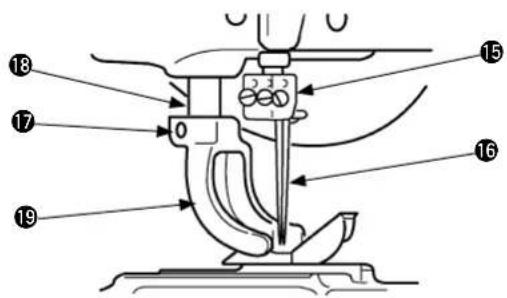
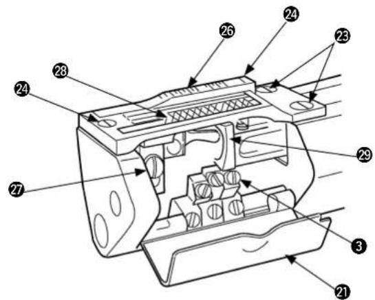
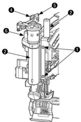
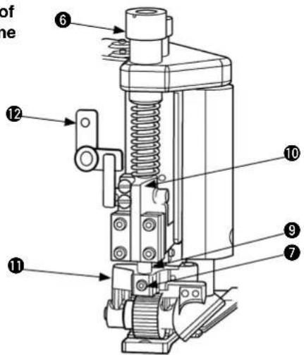
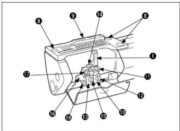
1. Names of machine head
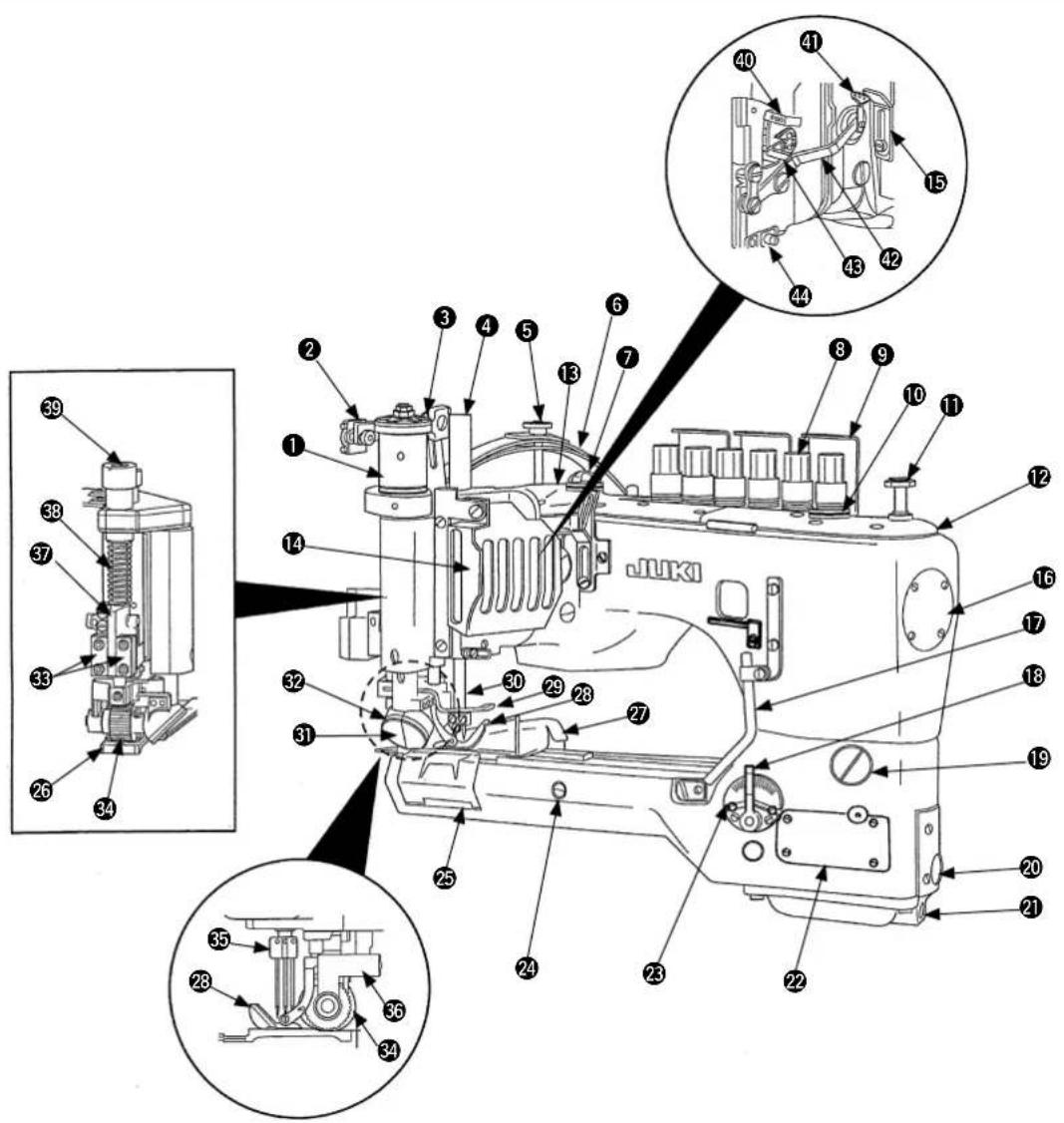
① Clutch asm.
② Clutch rod
③ Clutch lever
4 Cover for needle bar and roller
⑤ Pressure regulating nut
6 Pressure regulating plate spring assembly
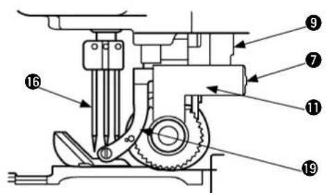
⑦ Oil circulation inspection window (rear)
8 Thread tension knob
9 Thread guide
⑩ Oil circulation inspection window (front)
11 Looper push button
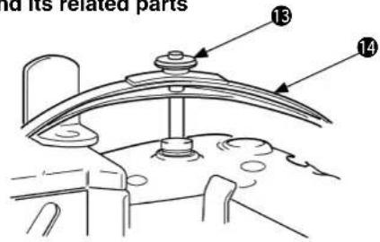
12 Front top cover
13 Rear top cover
14 Thread take-up lever oil guard
15 Needle thread adjusting path
16 End cover
17 Looper thread guide pipe
18 Differential feed adjusting lever
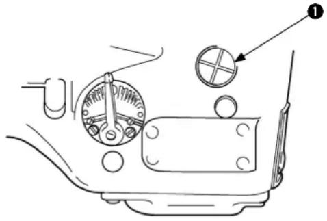
19 Window screw for both as stitch length adjustment and oil plug
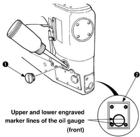
20 Oil gauge (front)
21 Oil discharge screw (front)
22 Cylinder side cover
23 Gauge plate
24 Feed rocking lever eccentric pin
25 Looper cover
26 Throat plate
27 Rolled hemming folder
28 Presser
29 Needle guard
30 Needle bar
31 Gear cover (front)
32 Gear cover (rear)
33 Upper feed roller frame
34 Upper feed roller
35 Needle clamp
36 Right and left guide plates
37 Roller bar guide plate
38 Roller pressure regulating spring
39 Roller pressure regulating screw
40 Needle thread lever-thread guide
41 Rocking thread take-up lever thread guide
42 Needle thread rocking thread take-up lever
43 Needle thread support adjust plate
44 Needle thread presser
2. Lubrication

WARNING :
Perform the work after turning OFF the power to prevent accidents caused by the abrupt start of the sewing machine.
Machine head with differential feed
(2) Oil drain spot
Machine head without differential feed
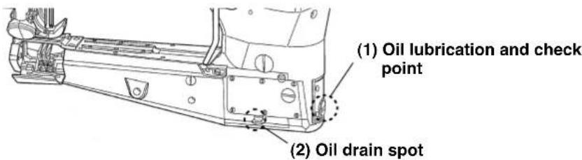
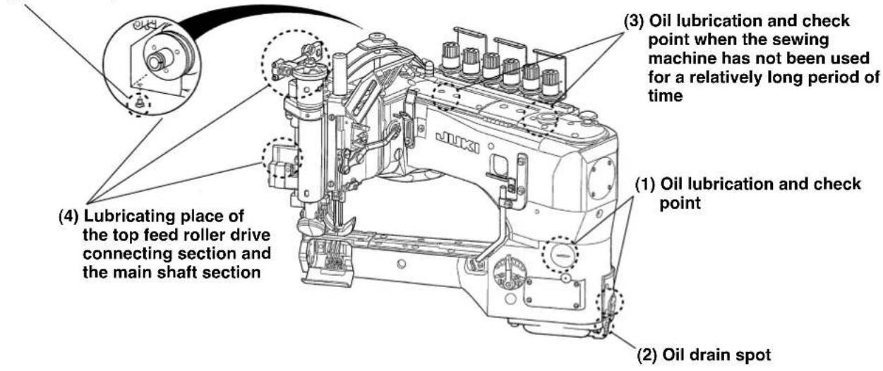
(1) Oil lubrication and check point
The sewing machine head section is of the rotary pump type auto lubrication system.
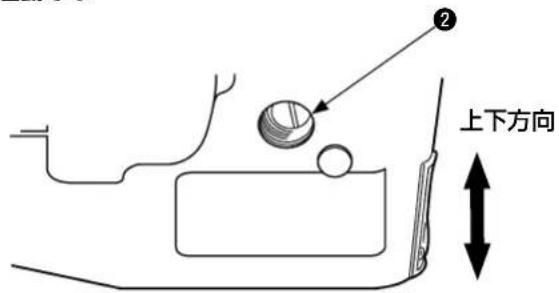
Remove oil plug ① and pour oil through the oil inlet until the upper engraved marker line on oil gauge (front) ② is reached. When starting pouring the oil, the oil is firstly fed to the rear part of the machine head. Therefore it appears that the oil level observed on the oil gauge gradually decreases. After running the machine for several hours, the oil amount becomes stable. At this time, re-check the oil level and add oil until the intermediate height between the upper and lower engraved marker lines is reached.

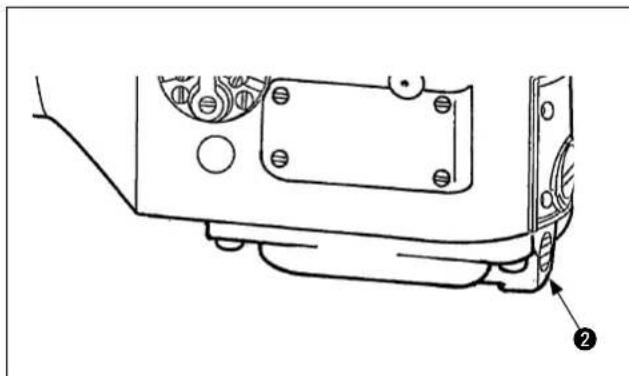
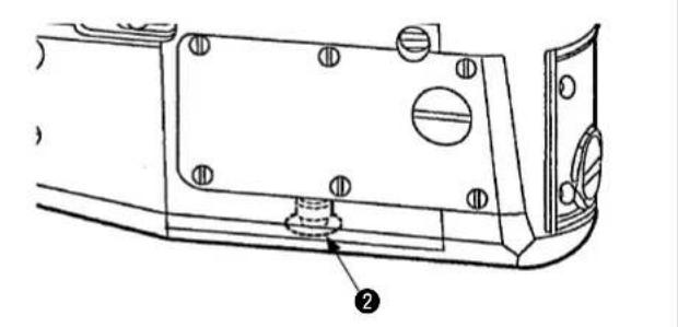
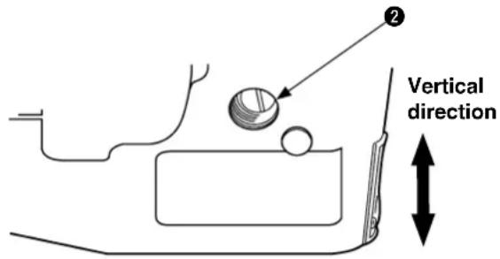
(2) Oil drain spot
To replace the lubricant, remove the oil drain (front) and (rear) screws ② and ①. Upon the completion of oil drainage, tighten the oil drain (front) and (rear) screws ② and ①.
natural_image
Technical line drawing of a mechanical component with mounting holes and a numbered annotation (no text or symbols present)Machine head without differential feedMachine head with different
natural_image
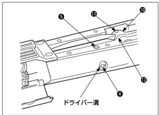
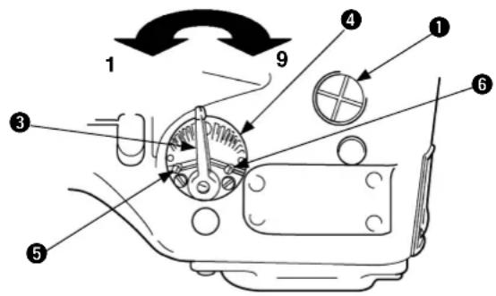
Technical line drawing of a mechanical component with mounting holes and a numbered annotation (no text or symbols present)(3) Oil lubrication and check point when the sewing machine has not been used for a relatively long period of time
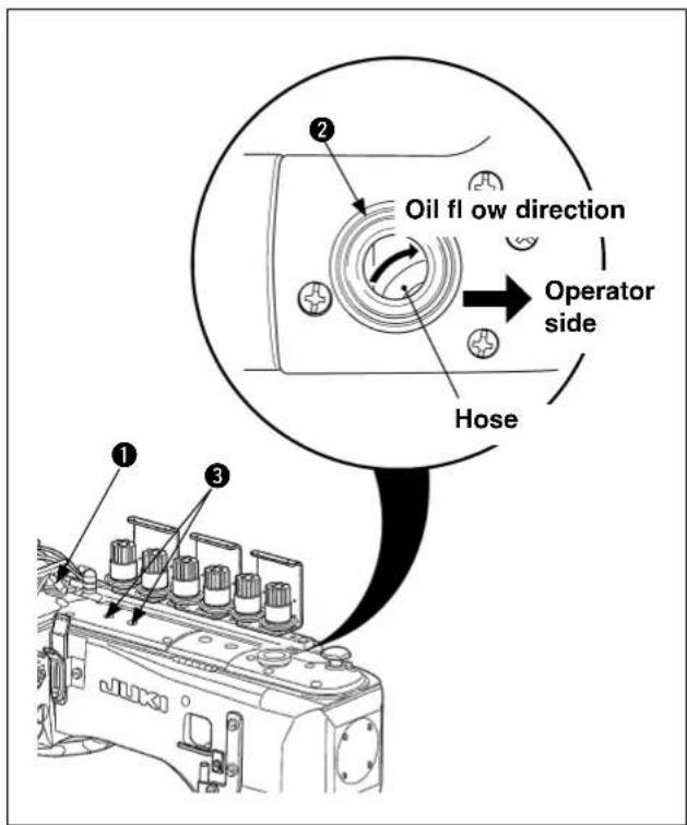
When the sewing machine has not been used for a relatively long period of time or something has been done to the components related to oil circulation at the time of maintenance and inspection, there is a case where the circulation function of oil has been lost. This occurs because air enters in the circulation route.
In this case, it can be checked with oil circulation check windows ① and ②.
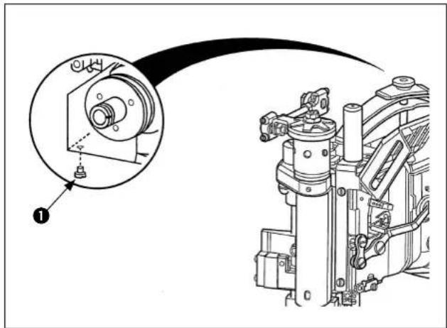
When the circulation of oil cannot be checked, remove two pump screws of ③, apply a few drops of oil until the oil surface can be checked there.
(4) Lubricating place of the top feed roller drive connecting section and the main shaft section
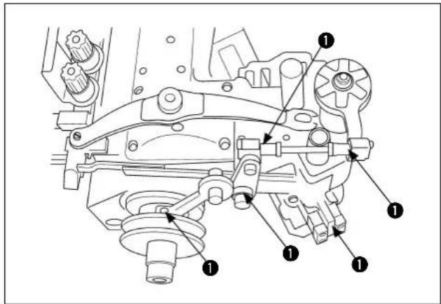
Apply one or two drops of oil once a week to five points ① of the upper feed roller drive connecting section and the main shaft section once every week.
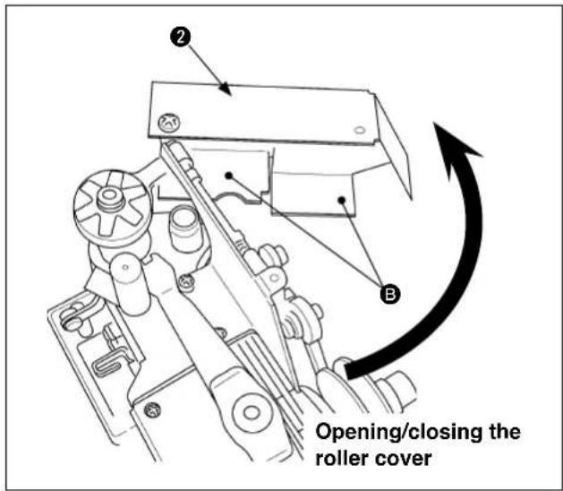
When applying oil to the top feed roller drive connecting section, perform oiling by opening and closing roller cover ②.
In addition, when oil adheres to oil receiving sections B of roller cover 2, wipe it out.
Perform oiling to the main shaft section by removing the rubber plug of the belt cover when using MT03.
Remove the thumbscrew when opening and closing the roller cover.
(5) Grease applying place
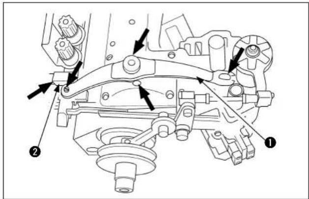
Apply grease supplied with the machine as the accessories every three months, as a standard, to the respective slide sections of presser spring ① and presser lifting bracket ②.
Remove the roller cover and apply grease

(Part No.: 40013640) supplied with the unit to joining part Ⓐ of main shaft and hook driving shaft.
3. Checking the direction of rotation
natural_image
Technical line drawing of a mechanical assembly with gears and levers (no text or symbols)Direction of rotation of the sewing machine is the same as that of the hand of watch as viewed from the handwheel side.
It is counterclockwise as viewed from the working position of the operator.

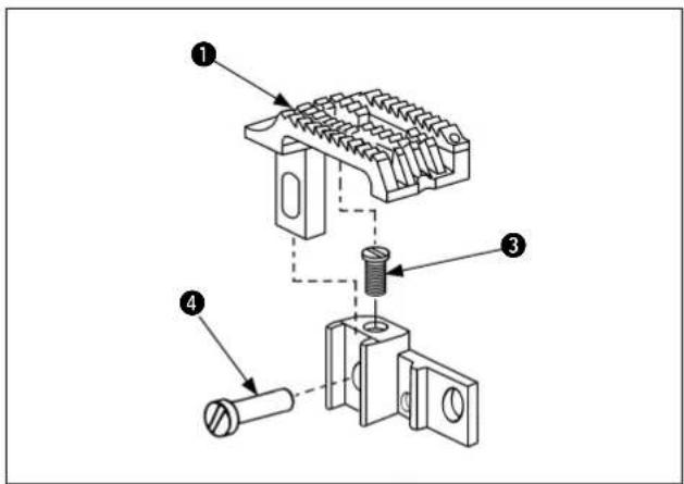
4. Attaching the needles
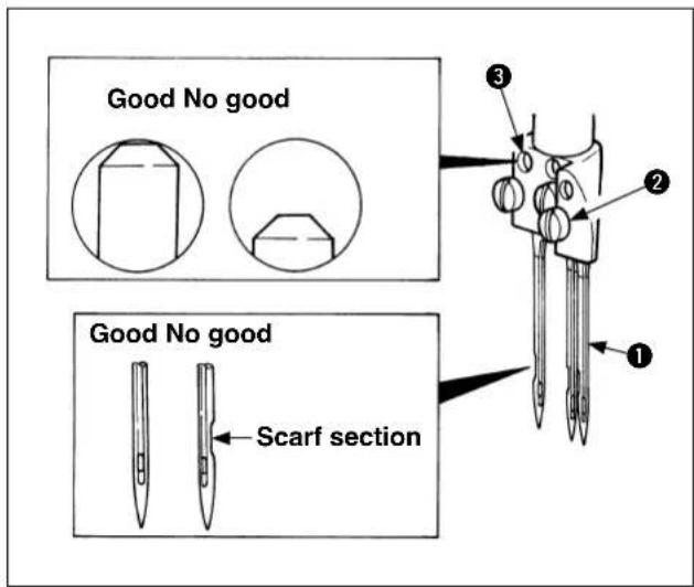
1) Loosen setscrew of needle ① with a screwdriver.
2) Insert new needles until they go up to the rear of the hole of needle clamp ③ in the way that the scarf is facing rearward as viewed from the operator's direction.
3) Tighten setscrew of needle.
5. How to pass the threads
(1) With differential feed (MS-3580SF/1SN)

WARNING :
Perform the work after turning OFF the power to prevent accidents caused by the abrupt start of the sewing machine.
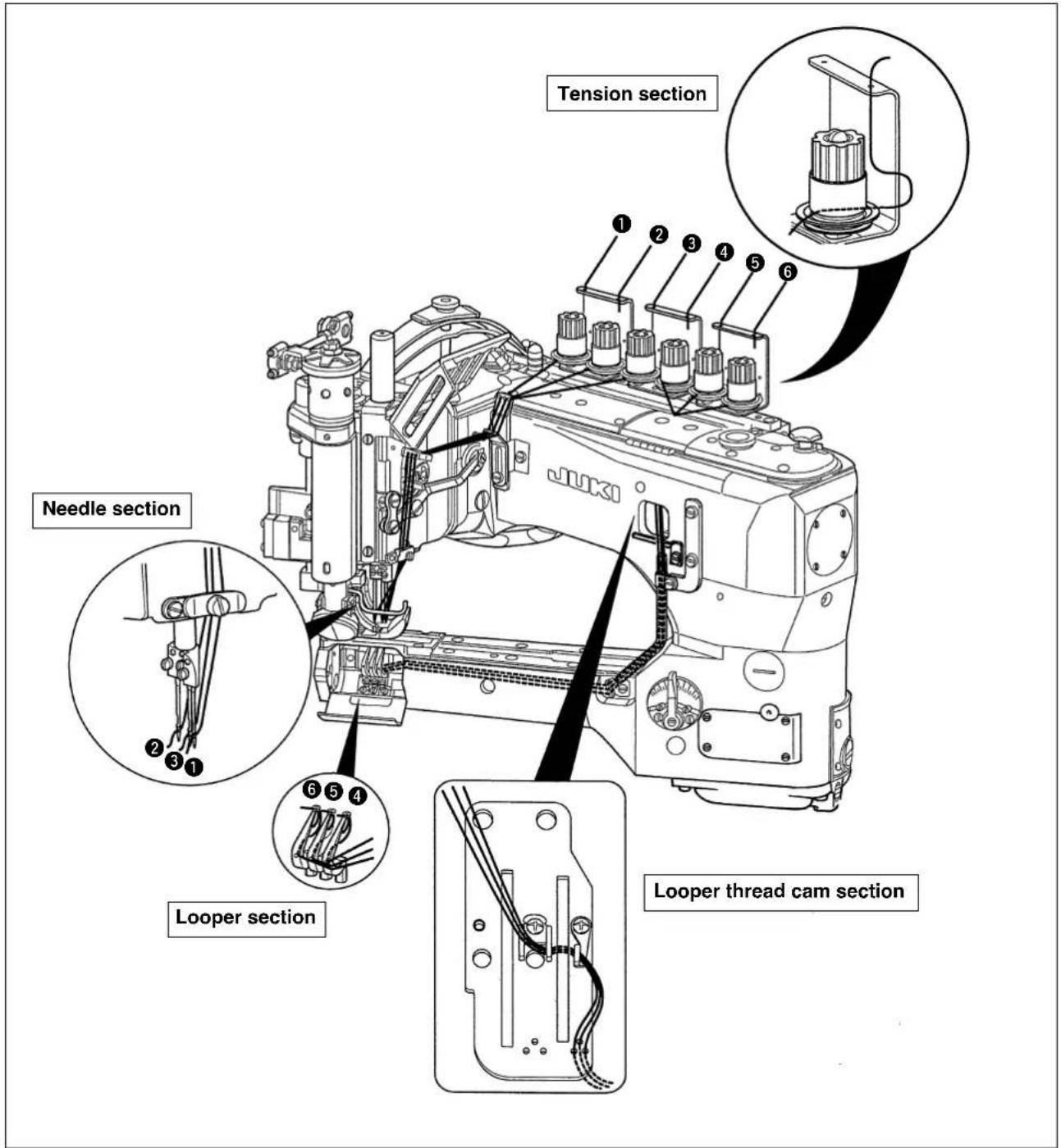
1) Threading diagram for the machine with differential feed
Needle thread : ① for left needle thread, ② for middle needle thread, ③ for right needle thread
Looper ④ for front looper, ⑤ for middle looper, ⑥ for rear looper
Perform threading in accordance with the threading diagram.
(2) Without differential feed (MS-3580SF/0SN)

WARNING :
Perform the work after turning OFF the power to prevent accidents caused by the abrupt start of the sewing machine.
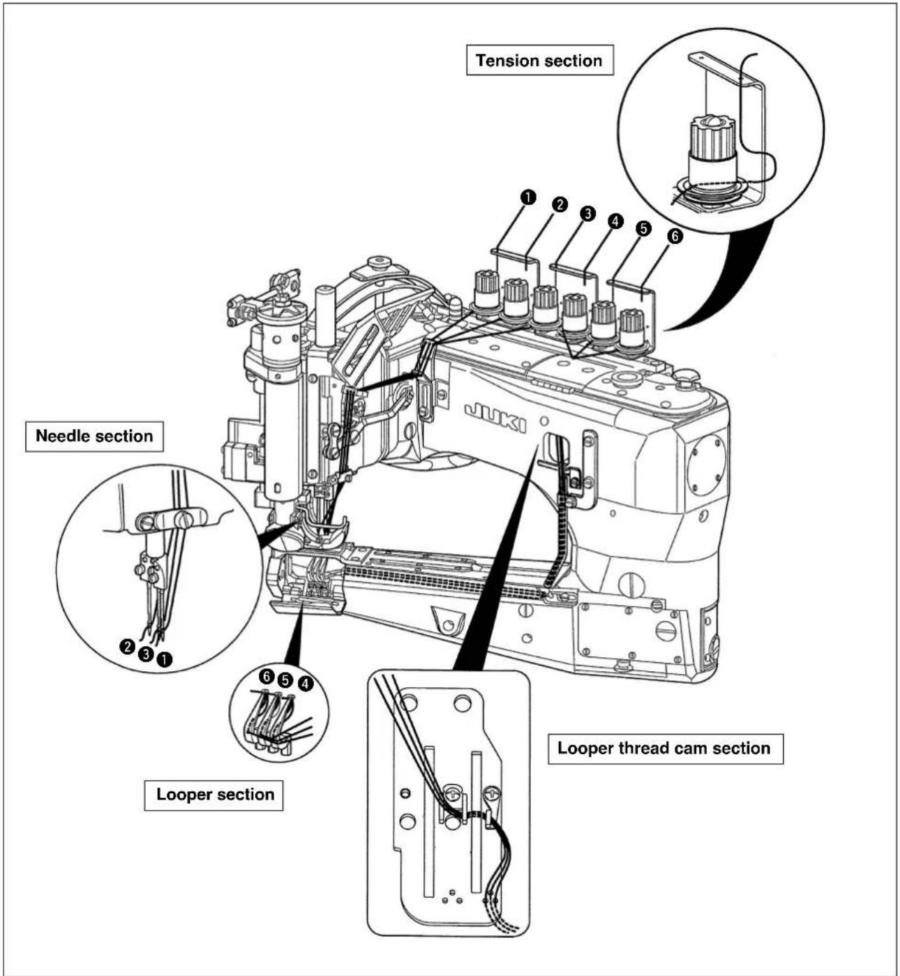
1) Threading diagram for the machine without differential feed
Needle thread: ① for left needle thread, ② for middle needle thread, ③ for right needle thread
Looper ④ for front looper, ⑤ for middle looper, ⑥ for rear looper
Perform threading in accordance with the threading diagram.
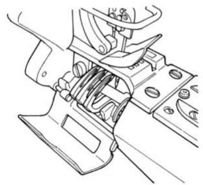
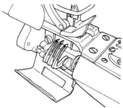
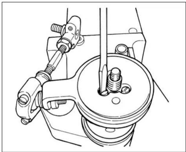
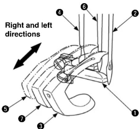
(3) looper

WARNING :
Perform the work after turning OFF the power to prevent accidents caused by the abrupt start of the sewing machine.

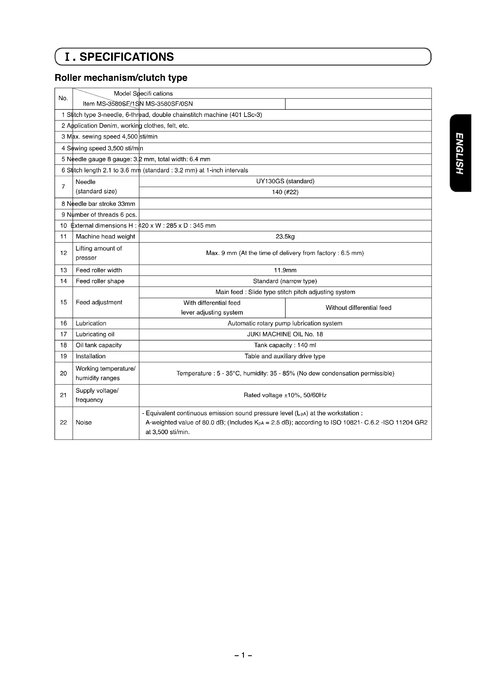
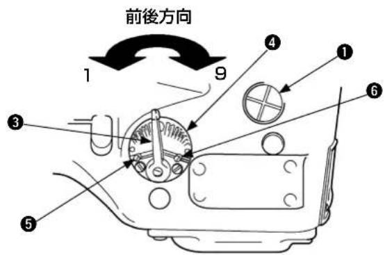
1) When passing the looper threads, press knob A near the lower dead point of needle bar and the loopers tilt front to facilitate to pass the threads.
Accordingly, perform threading with the loopers tilted front.
State before loopers tilt
natural_image
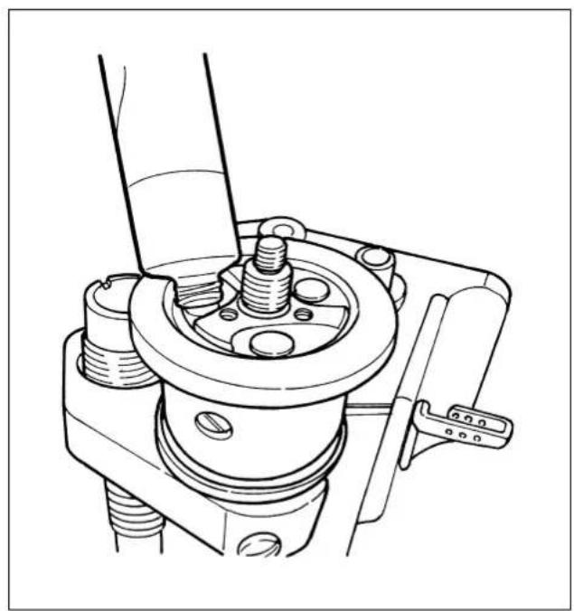
Technical line drawing of a mechanical assembly with no visible text or symbolsState loopers tilted

natural_image
Technical line drawing of a mechanical assembly with no visible text or symbols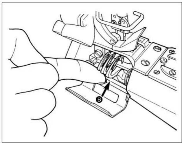
natural_image
Technical line drawing of a mechanical assembly with a hand operating a component (no text or symbols visible)2) After threading, press loopers of Ⓑ and they return to their home positions as shown in the figure.
When rotating the sewing machine with

loopers tilted front, be sure to return them to their home positions since they may come in contact with the cover or fingers may be caught in them.
6. Presser adjustment

WARNING :
Perform the work after turning OFF the power to prevent accidents caused by the abrupt start of the sewing machine.
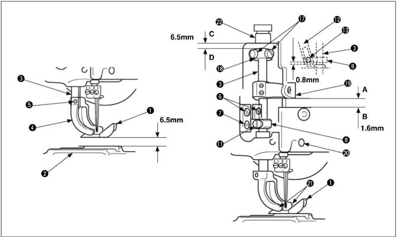
(1) Adjustment of amount of rise of presser
The standard amount of rise is 6.5mm for the standard class of the presser ① . (Maximum amount of rise : 9 mm) In standard positioning, the presser ① begins to rise faster by 3.2mm above the upper face of the throat plate ② before the upper feed roller begins to rise.
(2) Adjustment of presser bar pressure
Proper pressure of the presser ① shall be applied to the material while it is sewn. Turn the pressure adjusting nut ⑩ clockwise and counterclockwise to adjust pressure.

(3) Installation and pressure adjustment of presser and presser yoke
1) Raise the presser shaft ③, mount the presser yoke ④ on the presser shaft ③, and tighten the setscrew ⑤.
2) Confi rm whether the presser shaft ③ smoothly moves up and down, being free from rattling on the right and left.
If there is rattling on the right and left, loosen four setscrews ⑥ to set up the presser shaft guide ⑧ to eliminate right and left rattling by means of the right/left holding guide plate ⑦. Make adjustments to permit the presser shaft to perform light movement up and down.
Since then, tighten the setscrew 6.
3) Install the pressure adjusting leaf spring set ⑨ and turn the pressure adjusting nut ⑩ until pressure of the presser ⑪ is duly adjusted.
○ Turning the pressure adjusting nut ⑩ clockwise causes the pressure to increase.
○ Turning the pressure adjusting nut ⑩ counterclockwise causes the pressure to decrease.
4) In order to make the presser ① rise by 3.2mm faster than the upper feed roller, loosen the setscrew ⑪ of the presser shaft guide ⑧ and move the presser shaft guide ⑧ up and down until a clearance of 0.8mm is secured between the lower hole face of the lever link ⑫ and the bottom face of the lever link hanger setscrew ⑬ . (Lower dead point of the needle bar)
When the above-mentioned adjustments are made, the connecting positions shall be secured for the lifter lever 14 with slide hole and the lifter lever 15 by moving the lifter lever 14 with slide hole in the right direction. When proper positioning has been secured, tighten the setscrew 16.
5) To secure the standard amount of rise of 6.5mm for the presser ① , loosen the setscrew ⑰ and move the stop collar ⑱ up and down until a clearance of 6.5mm is secured between the lower face "C" of the mounting position of the presser shaft guide bush ⑲ and the upper face "D" of the stop collar ⑳ . Since then, tighten the setscrew ⑰ .
-
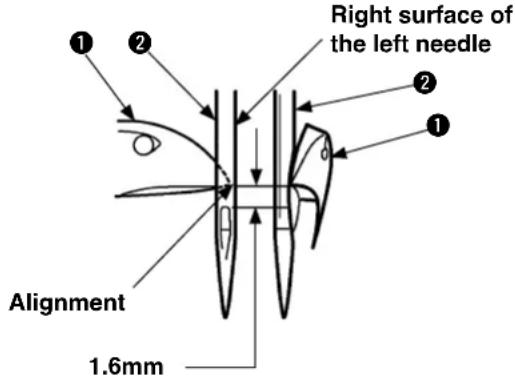
At the same time, check the mounting position of the needle thread rocking thread take-up lever connecting base 19.
-
At the lower dead point of the needle bar, a clearance of 1.6mm shall be secured between the bot-

-
If the amount of presser rise is too excessive than required, the presser will touch the needle clamp, thus causing needle breakage or stitch skipping.
-
If pressure of the presser is too insufficient or excessive than required, the material cloth will advance awkwardly.
(4) Removal and installation of presser only
To replace presser ① only, loosen the right and left setscrews ② and change the presser ①.
Then, tighten the right and left setscrews 21.
7. Adjustment of feed mechanisms

WARNING :
Perform the work after turning OFF the power to prevent accidents caused by the abrupt start of the sewing machine.
(1) Adjustment of stitch length (standard: 8 stitches/inch interval))
With differential feed
The stitch length can be adjusted within the range of 2.1 to 3.6 mm. Standard adjustment is 3.2 mm.
For the adjustment of the stitch length, loosen the lever setscrew ② and move the lever upwards or downwards until the required length is secured.
If the stitch length has been changed,
check "IV-7. Adjustment of rear needle guard" and make a proper readjustment.

stitch length within the range of 2.1 to 3.6 mm. If the stitch length is set to 3.6 mm or more, Do not set the stitch length to 3.6 mm or more since the interference of components may be caused.
Without differential feed
When the stitch length adjusting window screw ① is removed, the lever setscrew ② can be seen.
○ Loosen the lever setscrew ② to move the lever upwards and fasten the lever setscrew ② there. This action increases the stitch length.
○ Loosen the lever setscrew ② to move the lever downwards and fasten the lever setscrew ② there. This action decreases the stitch length.
- No graduation is available for the adjustment of the stitch length.
- When the stitch length is changed
If the forward or backward movement of

the main feed dog is changed, the contact amount is also changed between each needle and the rear needle holder. Since this can be a cause of stitch skipping the rear needle holder should be readjusted
(2) Adjustment of differential feed amount
Front-rear direction
In the case misalignment between the right and left materials occurs during sewing, adjust so that they are sewn with properly aligned by means of differential feed adjusting lever ③.
Scale plate ④ has markings numbered from 1 to 9. When differential feed adjusting lever ③ is set at the marking 5, the differential feed ratio of the differential feed amount to the main feed amount is 1:1. Turn the adjusting lever toward the marking 1 to decrease the differential feed amount or toward the marking 9 to increase it.

erential function is provided to the mechanism without differential feed.
○ In the case the right material is fed faster than the left one
Turn differential feed adjusting lever ③ toward markings 1 to 4 to adjust the misalignment between the right and left materials.
○ In the case the right material is fed slower than the left one
Turn differential feed adjusting lever ③ toward markings 6 to 9 to adjust the misalignment between the right and left materials.
※ When fixing the differential feed adjusting lever ③, pinch it with two setscrews ⑤ and ⑥.
8. Adjustment of drawing amount of upper feed roller

WARNING :
Perform the work after turning OFF the power to prevent accidents caused by the abrupt start of the sewing machine.
natural_image
Technical line drawing of a mechanical assembly with gears and shaft (no text or symbols)(1) Drawing amount of upper feed roller
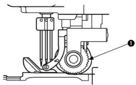
The standard amount of draw for the upper feed roller ① is defined to cause a slight pulling force for the sewing length (8 stitches/inch) of the feed dog.
The clutch connecting lever ② and the clutch set ③ are connected. The amount of draw for the material cloth can be changed by moving the clutch connecting rod ④ vertically.
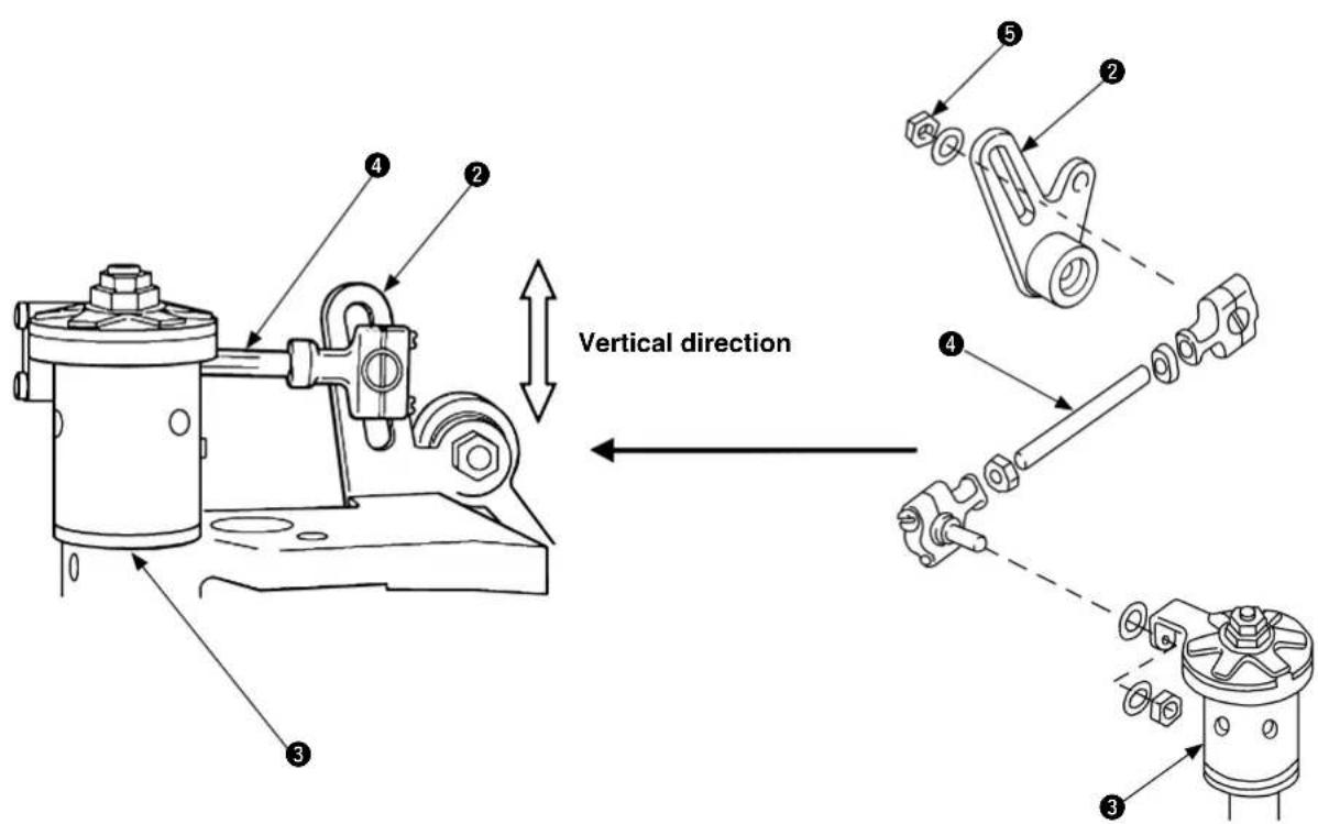
Loosen the nut ⑤, tighten the nut ⑤ after adjusting the clutch connecting rod ④ vertically.
- When the clutch connecting rod ④ is raised, the amount of draw for the material cloth is increased.
-
When the clutch connecting rod ④ is lowered, the amount of draw for the material cloth is decreased.
-
If the amount of draw for the upper feed roller
① is too much in conjunction with the sewing feed
amount, the number of stitches is increased.

amount of draw for the upper feed roller
① is too less, sewing problem occurs and this is a
cause of feed error. In particular, this problem occurs around the hinged section.
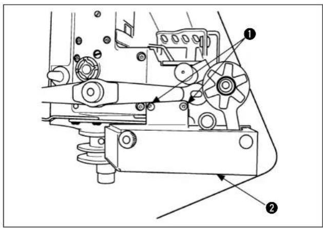
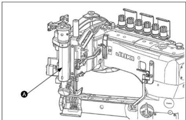
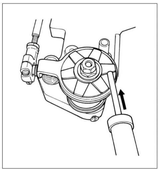
(2) How to fill grease into the upper feed roller and to adjust the brake spring
When the grease inside the upper feed roller has reduced, the amount of feed may be inconsistent or large noise may be generated. In such a case, carry out the following steps of procedure.
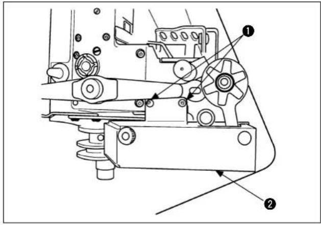
1) Remove setscre①. Remove cloth puller cover ②.
natural_image
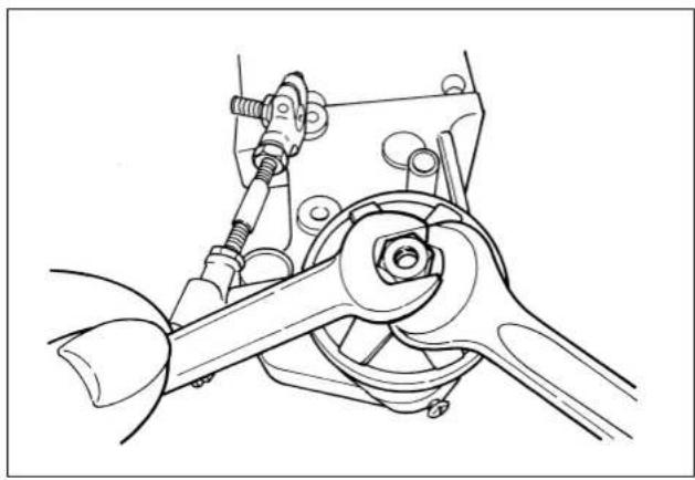
Technical line drawing of a mechanical assembly with springs and gears (no text or symbols)2) Remove the nut which secures the clutch lever with a spanner.
natural_image
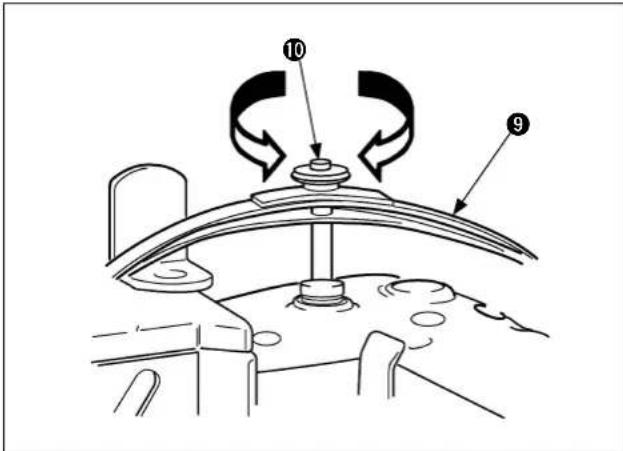
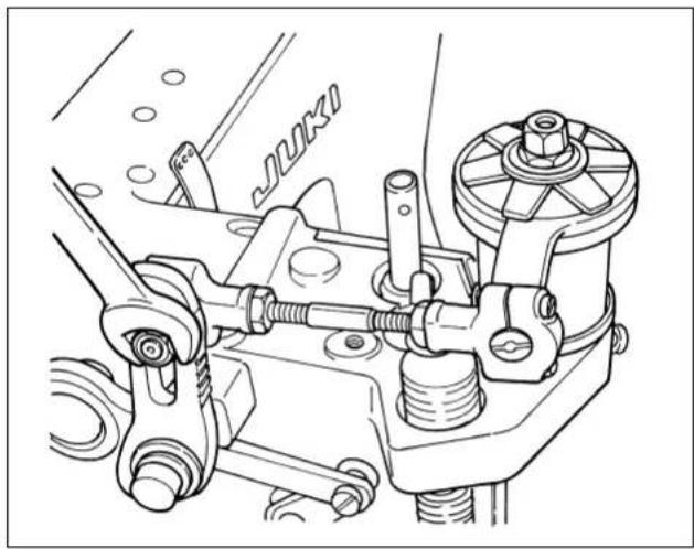
Technical line drawing of a mechanical assembly with no visible text or symbols3) Loosen two nuts with two spanners to remove the washer and brake spring from under the nuts.
natural_image
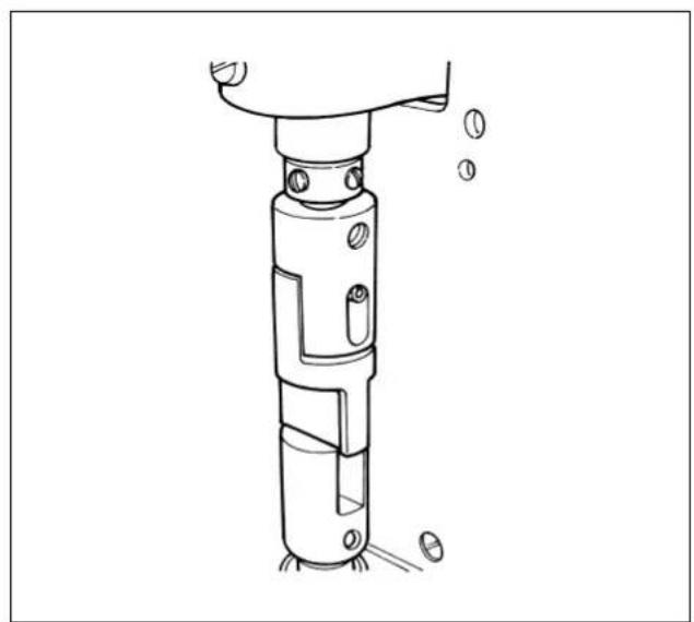
Technical line drawing of a mechanical assembly with springs and a central component (no text or symbols)4) Remove three setscrews to remove the clutch driving lever.
natural_image
Technical line drawing of a mechanical assembly with bolts and a clamp (no text or symbols)5) Fill the grease (Part No.: 40013640) supplied with the unit to the entire periphery of the clutch roller.
The clutch roller has two layers, upper and lower. For the sake of maintenance, only the upper layer should be filled with grease since the grease will gradually flows down to the lower layer.
natural_image
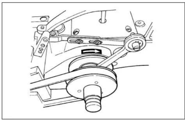
Mechanical assembly diagram showing a rotating component with a directional arrow indicating motion (no text or symbols present)6) Reassemble the removed parts back to their former state. Finally, adjust the brake spring pressure by the tightening amount of the two nuts.
For the standard adjustment, the upper feed roller rotates by pressing the spring balance as shown in the figure at left against the roller to apply a pressure of 10N to 30N.
The efficiency of feed may need to be increased in accordance with sewing conditions.
In such a case, increase the pressure.
natural_image
Technical line drawing of a mechanical device with no visible text or symbols7) When fi lling grease into the upper feed roller, the grease should be applied to the sliding part of the roller for increased smoothness of the roller connector.
If the upper feed roller loses its smoothness, the rotational resistance which causes the entire upper feed roller unit to feed smoothly will deviate.
IV. STANDARD ADJUSTMENT
1. How to remove the gauge components and upper feed roller (mechanism with differential feed and mechanism without differential feed)

WARNING :
Perform the work after turning OFF the power to prevent accidents caused by the abrupt start of the sewing machine.
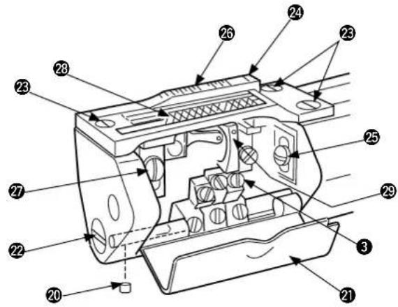
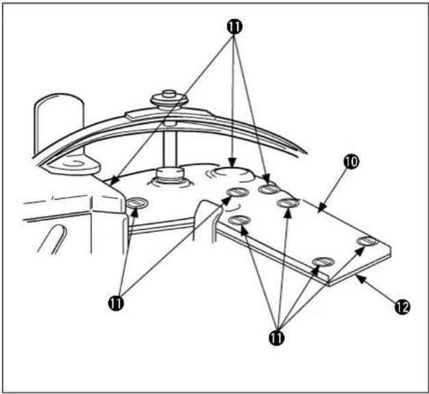
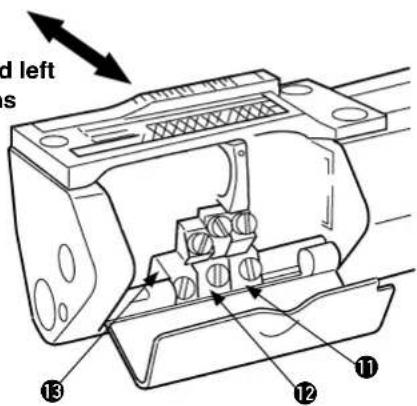
To perform the standard adjustment, remove the gauge components " needle 16, presser yoke 19, throat plate 24, differential feed dog 26, and main feed dog 28 ", the cover components " needle bar roller cover 2, and looper cover 21 ", upper feed roller frame 11 components, roller pressure regulating screw 6, and pressure regulating plate spring ssembly 14 before adjustment.
Left side of the machine head
The directions of front, rear, right, and left

during standard adjustment are based on the operator working position. Therefore, the forward rotation of the pulley is counterclockwise.
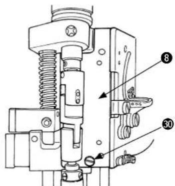
1) Loosen setscrew ^① and remove the needle bar and roller cover ^② .
2) Loosen setscreen and simultaneously remove side cover 8 and the packing.
3) Loosen n① and remove the washer and clutch connection rod ⑤.
4) Remove roller pressure regulating screw ⑥.
5) Loosen setscre ^7 in the upper feed roller shaft, lift upper feed roller shaft 9 and roller bar guide plate 10 and remove roller frame 11.
When the upper feed roller shaft ⑨ is lifted,

the guide fi nger⑩ interferes with the lift lever crank ⑫. Therefore, remove the upper feed roller assembly ⑪ after lifting the lift lever crank ⑫ slightly.
Rear side of the machine head
Right side of the machine head
Pressure regulating plate spring and its related parts
Left side of the machine head

Gauge components
(Mechanism with differential feed)
Gauge components
(Mechanism without differential feed)

6) Loosen the pressure regulating nut 13 and remove the pressure regulating plate spring assembly 14.
7) Loosen each setscrew 15 that securing corresponding needles and remove three of each needle 16.
8) Loosen the setsof securing the presser yoke and remove the presser yoke 19 after lifting the presser shaft 18.
9) Loosen the setscrew and remove the setscrew 21 securing the cover.
Removal of the setscrew allows you to remove the looper cover 22 and spring stud.
10) Loosen three setscrew ^23 securing the throat plate and remove the throat plate ^24 .
11) Loosen the setscrew 25 and remove the differential feed dog 26.
12) Loosen the setscre ^7 and remove the main feed dog ^28 .
13) Loosen the setscrew ③ securing the loopers ⑲ and remove the loopers ⑳.
The disassembly procedure mentioned
above mainly describes about the mechanism with differential feed.
mechanism without differential
feed, differential feed 26 and setscrew 25 are not provided.
2. Timing between the looper and needle bar

WARNING :
Perform the work after turning OFF the power to prevent accidents caused by the abrupt start of the sewing machine.
(1) Timing between the looper and needle bar (synchronization)
Gauge components are mounted to perform synchronization adjustment.
The standard position is that there is no clearance between the bottom surface of lower needle bar bushing ③ and the top surface of clip ④ when hexagonal wrench key (3 mm) ① touches throat plate ② by rotating the handwheel in the normal and reverse directions, (Be sure to rotate the handwheel in both directions to check the clearance.) The allowable clearance range is from 0 to 0.1 mm.

wallowable clearance between the hexagonal wrench key (3 mm)
① and the throat plate ② ranges
from 0 to 0.1mm when the bottom surface of the lower needle bar bushing ③ touches the top surface of the timing gauge ④ ahead of the other touch by rotating the pulley in both directions.
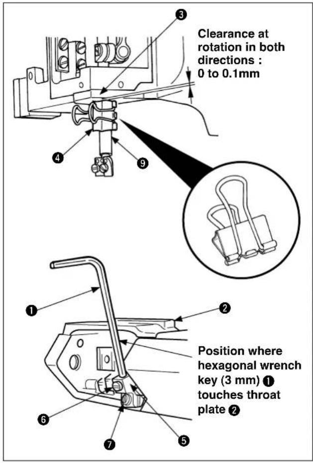
(2) Installing and adjustment procedure of the hexagonal wrench key and clip
1) Insert hexagonal wrench key (3 mm) ① into front looper base ⑤ and tighten setscrew ⑥.
2) Slightly loosen setscrew ⑦. Move looper base ⑤ into which the hexagon wrench key (3 mm) ① has been inserted until its leftmost point is reached.
3) Install throat plate ② and tighten setscrew ⑧
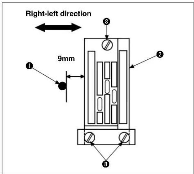
4) Turn the pulley to bring hexagonal wrench key (3 mm) ① to the leftmost point. Adjust the clearance measured from the right side face of the pulley to the left side face of throat plate ② to 9 mm. Then, temporarily tighten setscrew ⑦ in looper base ⑤. Further adjust the base to the correct position and securely tighten the setscrew.
5) Rotate the handwheel counterclockwise and stop it at the position where hexagonal wrench key (3 mm) ① touches the left surface of throat plate ②.
6) Attach clip ④ to needle bar ⑨.
* Attach a commercially-available alligator clip (small) with its upper face aligned with the mark-off line.
Attach clip ④ so that the top surface of clip ④ touches the bottom surface of lower needle bar bushing ③.
7) When the handwheel is rotated clockwise, hexagonal wrench key (3 mm) ① moves to the right and left. Touch the hexagonal wrench key with the left surface of throat plate ② again.
At this moment, make sure that the clearance between the bottom surface of lower needle bar bushing ③ and the top surface of clip ④ is within the allowable range.

The bottom surface of lower needle bar
bushing ③ may touch the top surface of clip ④ ahead of the other touch, in such a case, make sure that the clearance of the touching position between hexagonal wrench key (3 mm) ① and throat plate ② is within the allowable range.
8) If the timing between the looper (hexagonal wrench key (3 mm) ①) and needle bar ⑨ is inappropriate, follow the procedure below.

adjustment may cause stitch skipping or thread breakage.
(3) Corrective points and corrective measures
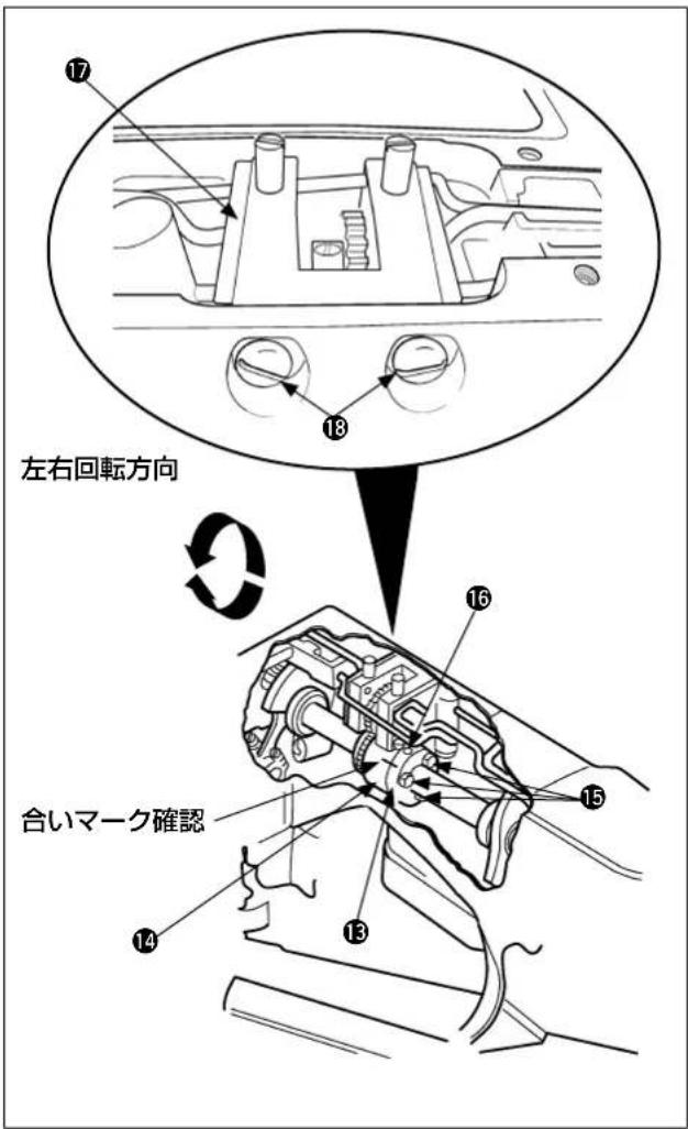
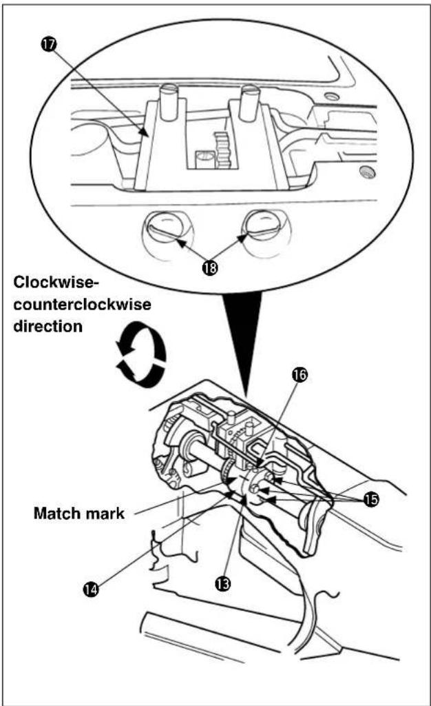
1) For adjusting the timing between the looper (hexagonal wrench key (3 mm) ①) and needle bar ⑨, loosen 9 setscrews ⑪ of rear top cover ⑩ and remove rear top cover ⑪ and packing ⑫.
2) Remove oil pump asm. ⑰ (which is fixed with two screws ⑱). Loosen three screws ⑲ in front and rear couplings ⑳ and ⑭ of the main shaft. Engage a key wrench with setscrew ⑮ in main-shaft front coupling ⑯ to turn the setscrew clockwise or counterclockwise for adjustment while keeping main-shaft rear coupling ⑰ from moving. Then reassemble the oil pump asm adjusting the backlash.
0.1 to 0.3 mm
* Loosen setscrews The backlash is increased by raising the oil pump or decreased by lowering it.
1. Align the match marks.
- For moving the front main shaft cou-

pling 13, temporarily tighten one of the fi xing nuts 15, which is close to the match mark, and make an adjustment.
To increase the clearance between hexagonal wrench key (3 mm) ① and throat plate ②, rotate front main shaft coupling ⑬ clockwise.
To decrease the clearance between hexagonal wrench key (3 mm) ① and throat plate ②, rotate front main shaft coupling ⑬ counterclockwise.
3) After adjustment, put the rear top cover ⑩ and packing ⑫ back on and tighten the setscrew ⑪.
3. Adjustment of the needle entry positions in the right-left and front-rear directions

WARNING :
Perform the work after turning OFF the power to prevent accidents caused by the abrupt start of the sewing machine.
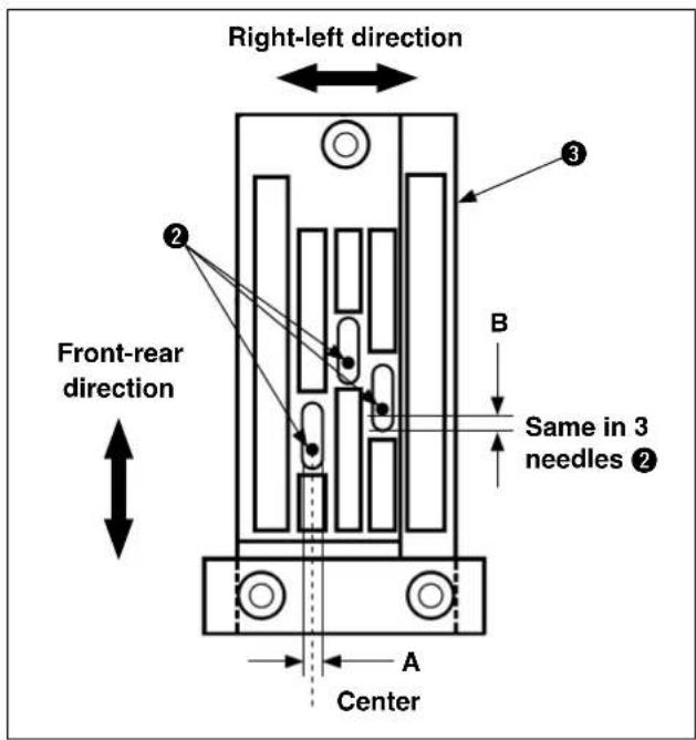
(1) Needle entry
1) Needle entry position in the right-left direction
Mount 3 needles
① to the needle clamp ② . The entry position "A" in the right-left center of the needle hole of the throat
2) Needle entry position in the front-rear direction
The standard needle entry position in the front-rear direction is decided under the condition that the clearance between the needle ② and needle hole of the throat plate ③, "B", is the same for all of 3 positions.
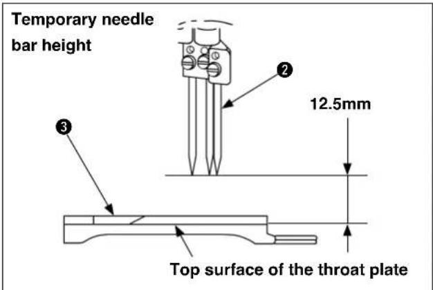
Adjust the needle entry position in accor-

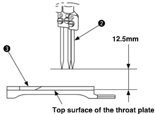
dance with the temporary needle bar ④ height of 12.5 mm.
Refer to "
IV-5. Adjustment of the needle bar
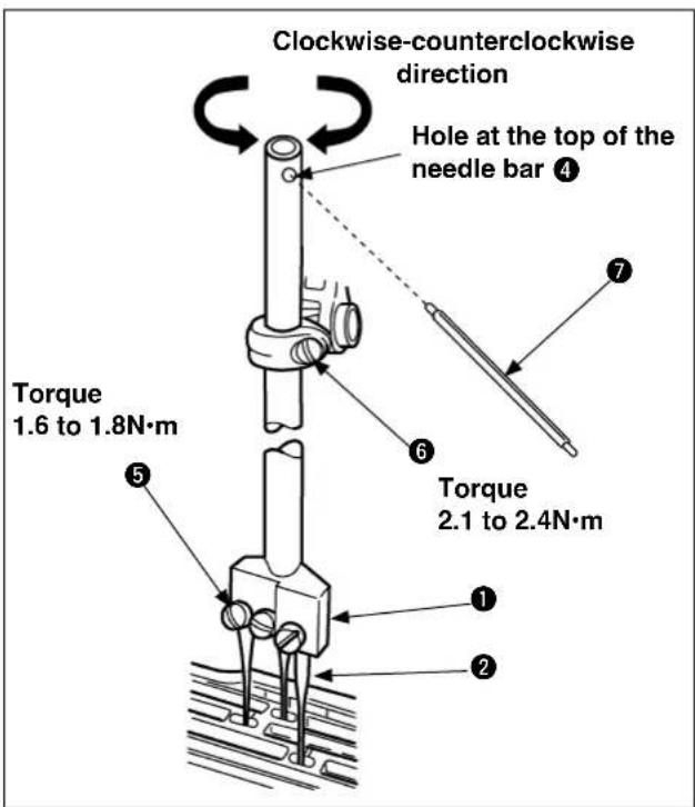
(2) Checking procedure of needle entry
1) Mount 3 need to the needle clamp ② and tighten the setscrew ⑤.
2) Loosen the needle bar holding screw ⑥ set the temporary needle bar ④ height (12.5 mm), and tighten the needle bar holding screw ⑥ temporarily (approximately needle bar ④ it turns).
3) Insert the torque rod ⑦ into the hole at the top of the needle bar ④ and rotate the needle bar ④ in the right-left direction to adjust the needle entry position in the front-rear and right-left directions.
-
Improper needle entry position adjustment may cause stitch skipping, needle breakage, or thread breakage.
-
Needle entry adjustment is performed in accordance with the temporary needle bar height.
When the needle bar is at the upper

dead point, the temporary clearance between the top surface of the throat plate ③ and the tips of the needles ② is 12.5 mm.
- The needle bar height is temporarily adjusted for needle entry adjustment. If there is no problem with the needle bar height, readjustment of the needle bar height is not required.
Advance to the next step.
4. Looper adjustment

WARNING :
Perform the work after turning OFF the power to prevent accidents caused by the abrupt start of the sewing machine.
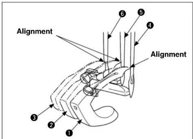
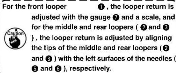
(1) Looper return
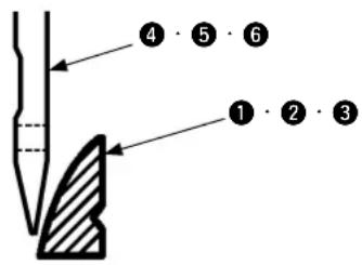
When each looper (1, 2 and 3) is at the most left position, the standard distance from the tip of each looper (1, 2 and 3) to the center of each needle (4, 5 and 6) is 3.6 ~mm .
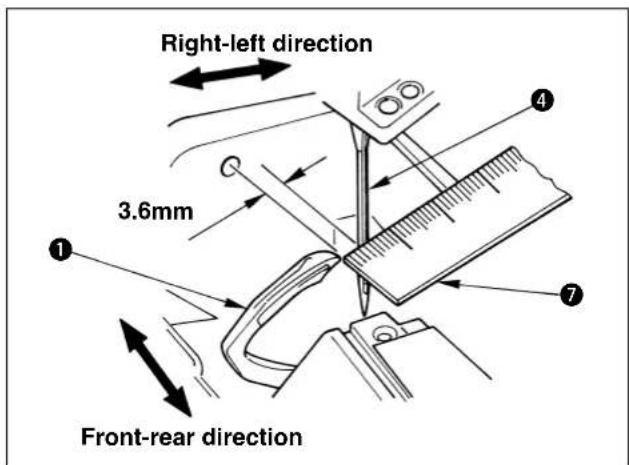
1) Standardization of the front looper
When front looper ① is at the most left position, measure the distance from the tip of front looper ① to the center of left needle ④ with scale ⑦ and adjust the distance to the standard value, i.e., 3.6 mm.
2) Standardization of middle and rear loopers
When the tips of the middle and rear loopers ( ② and ③ ) are simultaneously aligned with each left surface of the middle and right needles as well as the tip of the front looper ① with the left surface of the left needle ④ , the middle and rear loopers are in the standard positions.
(2) Front looper
1) Loosen the setscrews ⑧ to remove the throat plate ⑨.
2) Mount the front looper ① on the front looper base ⑩ and tighten the setscrew ⑪.
3) Rotate the handwheel in the direction of reverse rotation, move front looper ① to the most left position, and measure the clearance from the tip of front looper ① to left needle ④ with scale ⑦.
4) For adjusting the clearance to the standard distance, loosen the setscrew 12 securing the front looper base to adjust the position of the front looper base 10 in the right-left direction.
5) After adjustment, tighten the setscrew to secure the front looper base setscrew 12.
(3) Middle looper
1) Rotate the pulley counterclockwise and align the tip of the front looper ① with the left surface of the left needle ④.
2) Mount the middle looper ② on the middle looper base ⑬ and tighten the setscrew ⑭.
3) Loosen the sets of securing the middle looper base and move the middle looper base 13 in the right-left direction to align the tip of the middle looper 2 with the left surface of the right needle 5.
4) After adjustment, tighten the setscrew 15 to secure the middle looper base.
(4) Rear looper
1) Rotate the pulley counterclockwise and align the tip of the front looper ① with the left surface of the left needle ④.
2) Mount the rear looper ③ on the rear looper base ⑯ and tighten the setscrew ⑰.
3) Loosen the setscrew 18 securing the rear looper base and move the rear looper base 16 in the right-left direction to align the tip of the rear looper 3 with the left surface of the middle needle 6.
4) After adjustment, tighten the setscrew 18 to secure the rear looper base.
- When the positions of each looper base (
⑩, ⑬ and ⑱) are adjusted in the right-left direction,

adjust the clearances from the tips of the loopers (1, 2 and 3) to the needles (4, 5, and 6) as well.
- Insufficient or excessive looper return may cause stitch skipping, needle breakage, or thread breakage.
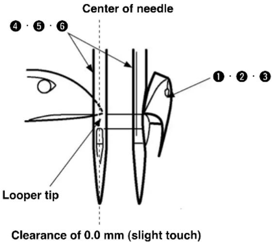
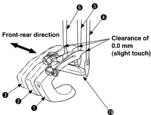
(5) Adjustment of the clearance between the looper and needle
When the tips of each looper (1, 2 and 3) are at the center of each needle (4, 5 and 6), the standard clearance is 0.0mm (slight touch).
After adjusting the rear needle guide 19, make sure again that the clearance between the loopers (1, 2 and 3) to the center of each needle (4, 5 and 6) is 0.0 mm respectively, and perform final adjustment of the clearance after threading.

nce adjustment is performed without the rear needle guide 19, a little strongly touch the tips of the loopers (4, 5 and 6) with the needles (1, 2 and 3), respectively.
1) Loosen the setscrews ( 12, 15 and 16 ) securing the looper bases to adjust the positions of the looper bases ( 10, 13 and 18 ) in the front-rear direction.
2) After adjustments, tighten the setscrews ( 12 , 15 and 16 ) to secure the looper bases.
1. When the positions of respective looper
bases (10, 13 and 18) are adjusted in the right and left directions, adjust the clearance from the tips of the respective loopers (1, 2 and 3) to the respective needles (4, 5 and 6) as well.
-
When each looper base (10, 13 and 13) is moved leftward, each tip of loopers (1, 2 and 3) is detached from each needle (4, 5 and 6).
-
When each looper base (10, 13 and 18) is moved rightward, each tip of loopers 1, 2 and 3) touches each needle (4, 5 and 6).
5. Adjusting the height of the needle bar

WARNING :
Perform the work after turning OFF the power to prevent accidents caused by the abrupt start of the sewing machine.
Alignment between the bottom surface of the looper and the top hole end of the needle
Alignment between the tip of the looper and the right surface of the needle
Temporary needle bar height
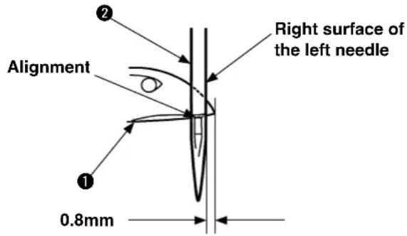
(1) Height of the needle bar
1) Alignment between the bottom surface of the front looper and the top hole end of the left needle
When the pulley is rotated counterclockwise and the bottom surface of the front looper ① is aligned with the top hole end of the left needle ②, the standard needle bar height is achieved by adjusting the distance from the tip of the front looper ① the right surface of the left needle ② to 0.8 mm.
2) Alignment between the tip of the front looper and the left surface of the left needle
When the pulley is rotated counterclockwise and the tip of the front looper ① is aligned with the right surface of the left needle ②, the standard needle bar height is achieved by adjusting the distance from the bottom surface of the front looper ① to the top hole end of the left needle ② to 1.6mm.

sting the needle bar height, select an easier-to-adjust one from either 1) or 2) mentioned above.
3) Checking of the middle and rear looper heights shall be also checking of each looper return.
- Needle entry adjustment is performed in accordance with the temporary needle bar height.
When the needle bar is at the upper
dead point, the temporary clearance between the top surface of the throat plate ③ and the tips of the needles ② is 12.5 mm.

- The needle bar height is temporarily adjusted for needle entry adjustment. If there is no problem with the needle bar height, readjustment of the needle bar height is not required.
Advance to the next step.
(2) Adjustment of the needle bar height
1) Remove the needle bar, roller cover, surface cover, and packing.
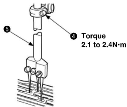
2) Loosen the setso④ and adjust the needle bar ⑤ position vertically.
3) After adjustment, tighten the setscrew 4.
- Use caution not to rotate the needle bar ⑤ at adjustment of needle bar height.
Failure to observe this changes needle entry positions.
- Remarkably improper needle bar height adjustment may cause stitch skipping, needle breakage, or thread breakage.
6. Adjustment of the looper motion paths

WARNING :
Perform the work after turning OFF the power to prevent accidents caused by the abrupt start of the sewing machine.
Model with differential feed
(1) Looper momentum in the front-rear direction
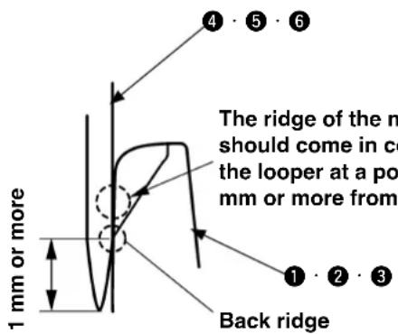
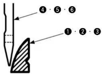
1) The standard position of the front looper ① is decided under the condition that the tip of the needle ④ touches the rear of the front looper ① at 1/3 from the bottom surface when the pulley is rotated counterclockwise and the front looper ① is moved from right to left after mounting the front looper ① in a standard manner.
2) While the looper is moving backward, the side face of the needle should comes in contact with the back side of the looper when the needle tip is 1 mm or more away from the middle of the back ridge of the looper.
(Front, middle and rear loopers)
When the material has a section which has

a large difference in height, the depth of back-to-back contact between the needle tips and loopers (② and ③) has to be decreased. (In order to prevent the needle tip from being crushed.)
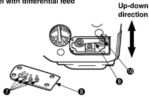
(2) Adjustment of longitudinal movement of the looper with differential feed
1) Loosen the setscrews ⑦ (4 pcs.) and remove the cylinder side cover ⑧.
2) Loosen the setscrew 10 of the ball joint 9 with a spanner wrench, and adjust the forward/reverse movement by moving the setscrew 10 forward or backward.
3) After adjustments, mount the cylinder side cover ⑧, and tighten the setscrews ⑦.
When reducing the front and rear momentum amount of the looper, move the ball joints ⑨ upwards.
When increasing the front and rear momentum amount of the looper, move the ball joints ⑨ downwards.
-
When the front and rear momentum of the looper has been adjusted, move the respective looper bases ⑪, ⑫ and ⑬, and readjust the front/rear positions of the needles ( ④, ⑤ and ⑥ ) and the loopers ( ①, ② and ③ ).
-
When the above-mentioned adjustments are carried out, the throat plate should be removed.
-
When the front and rear momentum amount of the looper is small :

amount of contact becomes large between tips of the needles (
④, ⑤ and ⑥) and rear parts
of the loopers (①, ② and ③) and this can be a cause of needle tip being blunt.
- When the front and rear momentum amount of the looper is large :
The clearance becomes large between tips of the needles (4, 5 and 6) and rear parts of the loopers (1, 2 and 3) and this can be a cause of stitch skipping.
Model without differential feed
Right and directions
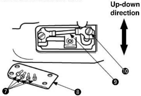
(3) Adjustment of longitudinal movement of the looper without differential feed
1) Loosen the setscrews ⑦ (4 pcs.) and remove the cylinder side cover ⑧.
2) Loosen the setscrew 10 of the ball joint 9 with a screwdriver, and adjust the forward/reverse movement by moving the setscrew 10 forward or backward.
3) After adjustments, mount the cylinder side cover ⑧, and tighten the setscrews ⑦.
When reducing the front and rear momentum amount of the looper, move the ball joints ⑨ upwards.
When increasing the front and rear momentum amount of the looper, move the ball joints ⑨ downwards.
1. When the front and rear momentum of
the looper has been adjusted, move the respective looper bases ⑪, ⑫ and ⑬, and readjust the front/rear positions of the needles ( ④ , ⑤ and ⑥ ) and the loopers ( ① , ② and ③ ).
2. When the above-mentioned adjust-
ments are carried out, the throat plate ⑭ should be removed.
3. When the front and rear momentum

amount of the looper is small :
nt of contact becomes large between tips of the needles ( ④ , ⑤ and ⑥ ) and rear parts of the loopers ( ① , ② and ③ ) and this can be a cause of needle tip being blunt.
4. When the front and rear momentum
amount of the looper is large :
The clearance becomes large between
tips of the needles (④, ⑤ and ⑥) and rear parts of the loopers (①, ② and ③) and this can be a cause of stitch skipping.
7. Adjustment of rear needle guard

WARNING :
Perform the work after turning OFF the power to prevent accidents caused by the abrupt start of the sewing machine.
Longitudinal directions of rear needle guard
Vertical direction of rear needle guard
Up-down direction
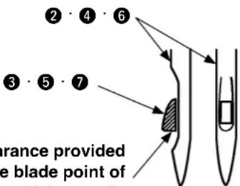
When the right side face of the needle is aligned with the blade point of the looper
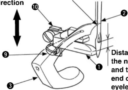
Distance between the needle guard and the bottom end of the needle eyelet : 0.5 to 2 mm
The clearance provided between the blade point of the looper and the needle should be 0 to 0.05 mm.
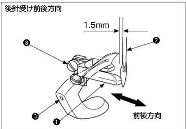
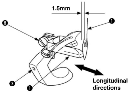
(1) Longitudinal adjustment of the rear needle guard
1) When the pulley is turned counterclockwise and the rear needle guard ① advances to the most front position, it lightly touches the left needle ② (If necessary, press it lightly so that all the needles can be guarded.) and then tip of the front looper ③ passes.
When tip of the front looper ③ reaches the position 1.5mm apart from the left side of the left needle ② while this front looper ③ moves in right direction, the standard position is that the needle tip comes in contact with the rear needle guard ①.
2) The relationship between the middle needle ④ and the rear looper ⑤ and between the right needle ⑥ and the middle looper ⑦ is also required to assume the same conditions as (1) -1). above in standard positioning.
3) Loosen the sets and move the rear needle guard 1 forward or backward to adjust.
4) After adjustments, tighten the setscrew 8.
-
To change the stitch length, readjustment of the front and rear positions is also needed for rear needle guard ①.
-
When the rear needle guard is adjusted, recheck the non-presence of a clearance between the respective needles (②, ④ and ⑥) and the respective loopers (③, ⑤ and ⑦). If any clearance is perceived, readjust the related conditions.
-
In a clearance is actually developed between the respective needles (②, ④ and ⑥) and rear needle guard①, this can be a cause of needle breakage or stitch skipping.
-
When rear needle guard ① presses the respective needles (②, ④ and ⑥) too much, this can be a cause of needle tip being blunt.
(2) Height adjustment of rear needle guard
1) The relationship between the middle needle ④ and the rear looper ⑤ and between the right needle ⑥ and the middle looper ⑦ is also required to assume the same conditions as (1) -1) above in standard positioning.
2) Loosen the sets and move the rear needle guard base 10 vertically to adjust the height.
3) After adjustments, tighten the setscrew ⑨.
8. Adjustment of feed dog height and longitudinal movement (mechanism with differential feed)

WARNING :
Perform the work after turning OFF the power to prevent accidents caused by the abrupt start of the sewing machine.
(1) Height of main feed dog
The standard height is defined when the main feed dog ① attains the highest level and the root section of the main feed dog ① coincides with the upper face of the main feed dog throat plate ② .
(2) Height of differential feed dog
The standard height of the differential feed dog ③ is defined when the main feed dog① attains the highest level and bottom face "B" of differential feed dog ③ lightly touch upper face "A" of main feed dog ①.

Check for No bind.
(3) Adjustment of longitudinal movement of main feed dog
The maximum amount of feed of the main feed dog ① is 3.6 mm. (Standard : 3.2 mm)
When the main feed dog ① attains its maximum feeding amount, the standard positioning is secured when Clearance "C" and Clearance "D" are equalized. Clearance "C" is defined as the distance from the feed groove front section of the throat plate ② to the front section of the main feed dog ① in position where the main feed dog ② stays in the most advanced position. Clearance "D" is defined as the distance from the feed groove rear section of the throat plate ② to the rear section of the main feed dog ① in position where the main feed dog ① has attained the most retreated position.
(4) Adjustment of vertical height of main feed dog and differential feed dog
For the feed rocking lever eccentric pin ④ of the feed dog, the standard positioning of the groove is horizontal. The vertical height of the main and differential feed dogs (① and ③) can be simultaneously adjusted by turning the feed rocking lever eccentric pin ④. Basically, however, this function should be used in standard position.
(5) Gradient of main feed dog and differential feed dog
Front lowering condition is standard.
Height of main feed dog Height of differential feed dog

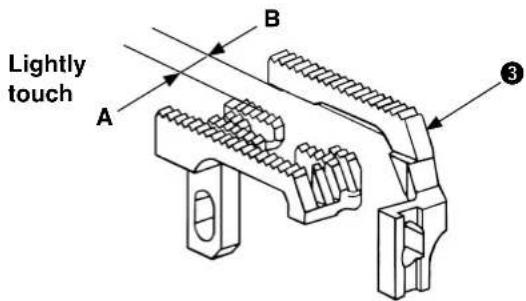
Clearance of the main feed dog in the most advanced position
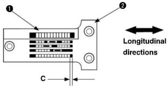
Clearance of the main feed dog in the most retreated position
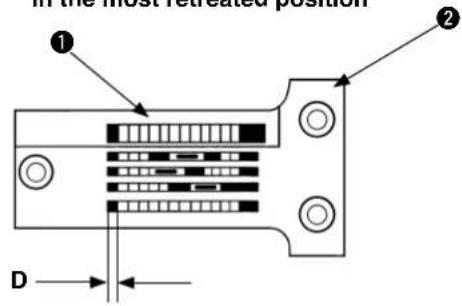
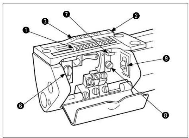
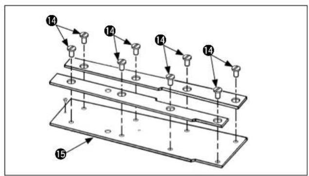
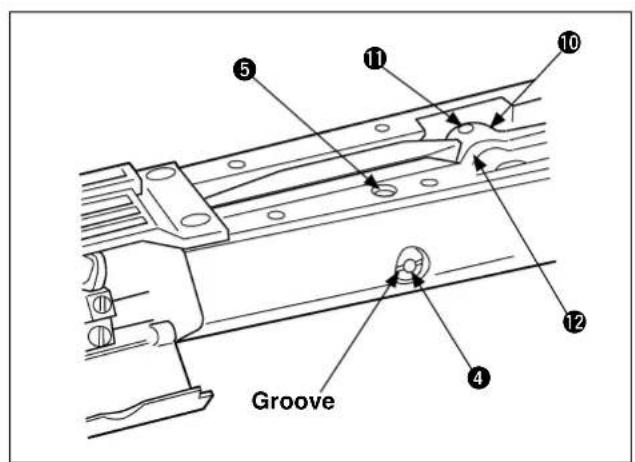
(6) Adjustment of main feed dog and differential feed dog
1) For the feed rocking lever eccentric pin ④ of the feed dog, the standard positioning of the groove is horizontal.
If the groove seems to be inclined deviating from the standard positioning, loosen the setscrew ⑤ and adjust the feed rocking lever eccentric pin ④ of the feed dog until it assumes its horizontal posture.
Since then, tighten the setscrew ⑤.
2) Mount the main feed dog ①, differential feed dog ③ and throat plate ② and fix the throat plate ②.
3) In the first place, adjust the height of the main feed dog ① to the standard position. Then fi x it by tightening the setscrew ⑥.
4) Apply the feed dog support ⑦ to the bottom of the front section of the main feed dog ① and tighten the setscrew ⑧.
5) Then, adjust the height of the differential feed dog ③ to the standard position. After that, fi x it by tightening the setscrew ⑨.
6) According to 7. Feed adjustments, (1) Adjustment of stitch length", adjust the maximum feed amount of the main feed dog to 3.6mm .
(Apply a ruler to the side of the main feed dog ① and confirm the result by turning the pulley counterclockwise.)
7) Turn the pulley counterclockwise and confi rm that there is no contact between the main feed dog ① and the feed groove front/rear section of the throat plate ②.
If there is any contact, loosen the setscrew 11 of the main feed rocking lever link 10 and turn the main feed rocking eccentric drive stud 12 to adjust the throat plate 2 not to contact the feed groove front/rear section. After adjustments, tighten the setscrew 11.
8) After the adjustment of the amount of forward and back movement of main feed dog ①, adjust the feed amount to the stitch length to be used (for sewing).
-
In the case of front and rear adjustments of the mechanism with differential feed, specific attention should be paid to the fi ne feed dog section of main feed dog ^① .
-
To make front and rear adjustments of the main feed dog ①, loosen eight setscrews ⑭ of the cylinder cover and remove the cylinder cover set ⑮. After adjustments, mount the cylinder cover set ⑮ and tighten the setscrews ⑭.
-
For the main feed dog ① and the differential feed dog ③, the longitudinal gradients and the horizontality are kept constant and cannot be adjusted.
-
Counter any adjustment of feed dog (①, ③) or this page recheck adjustment of rear needle guard on [IV-7. Adjustment of rear needle guard] and readjust as necessary.
-
When the height of feed dogs ①, ③ is insufficient ○ The amount of feed is decreased and uneven feeding can occur. ○ When the height of the rear needle guide is lowered, this will cause breakage of a needle or stitch skipping.
-
When the height of feed dogs ①, ③ is excessive
- This can be a cause of the materials pushed back to the front side, or of giving rise to feed fl aws.
- When the height of the rear needle holder is raised and the margin of the needle contact position is increased, this will cause failure in producing loops and stitch skipping.
9. Adjustment of feed dog height and longitudinal movement (mechanism without differential feed)

WARNING :
Perform the work after turning OFF the power to prevent accidents caused by the abrupt start of the sewing machine.
(1) Height of main feed dog
The standard height is defined when the main feed dog ① attains the highest level and the rear root section of the main feed dog ① coincides with the upper face of the throat plate ② of the main feed dog ① .
(2) Adjustment of longitudinal movement of main feed dog
The maximum amount of feed of the main feed dog ① is 3.6 mm. (Standard : 3.2 mm)
When the main feed dog ① attains its maximum feeding amount, the standard positioning is secured when Clearance "A" and Clearance "B" are equalized. Clearance "A" is defined as the distance from the feed groove front section of the throat plate ② to the front section of the main feed dog ① in position where the main feed dog ① stays in the most advanced position. Clearance "B" is defined as the distance from the feed groove rear section of the throat plate ② to the rear section of the main feed dog ① in position where the main feed dog ① has attained the most retreated position. (A = B)
Height of main feed dog
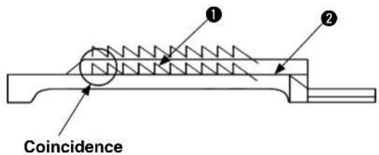
Clearance of the main feed dog in the most advanced position
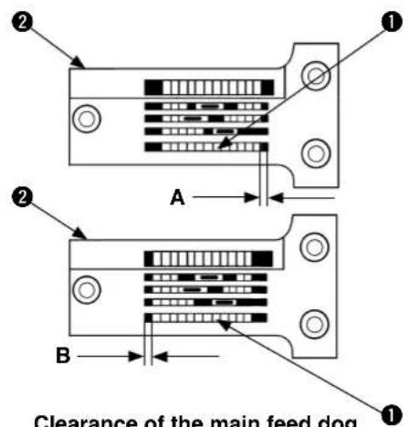
Clearance of the main feed dog in the most retreated position
(3) Adjustment of the vertical height of main feed dog
1) Apply the rear support screw ③ to the bottom right of the main feed dog ①, tighten the setscrew ④, and mount the throat plate ②.
2) Check the standard height of the main feed dog ①.
○ If the main feed dog ① is low, raise the rear support screw ③.
○ If the main feed dog ① is high, raise the rear support screw ③.
3) Remove the throat plate ②, loosen the setscrew ④ to remove the main feed dog ①, and adjust height of the front support screw ⑤.
4) After adjustments, mount the main feed dog ①, tighten the setscrew ④, mount the throat plate ②, and tighten the setscrew ⑥.
When the height of main feed dog insufficient
- The amount of feed is decreased and uneven feeding can occur.
When the height of the rear needle guide is lowered, this will cause breakage of a needle or stitch skipping.
When the height of main feed dog excessive
○ This can be a cause of the materials pushed back to the front side, or of giving rise to feed fl aws.
When the height of the rear needle holder is raised and the margin of the needle contact position is increased, this will cause failure in producing loops and stitch skipping.
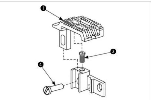
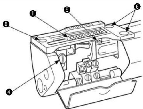
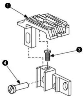

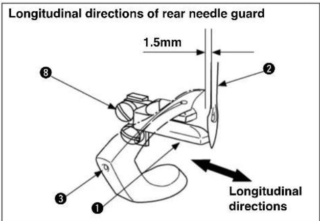
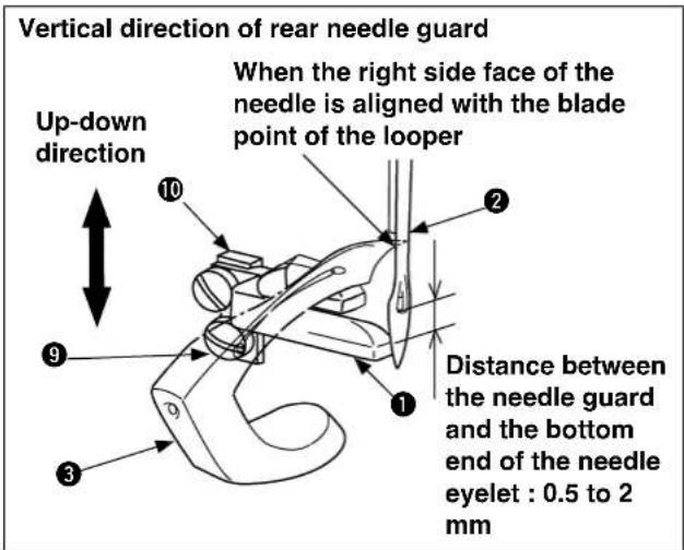
(4) Adjustment of longitudinal movement of main feed dog
1) Loosen the setscrews ( ⑦ and ⑧ ) and remove the plug female screw ⑨ .
2) Using a screwdriver, turn the eccentric pin ⑩ clockwise and counterclockwise until the front and rear positions of the main feed dog ⑪ are properly adjusted.
(5) Longitudinal adjustment of the rear needle guard
1) When the pulley is turned counterclockwise and the rear needle guard ① advances to the most front position, it lightly touches the left needle ② (If necessary, press it lightly so that all the needles can be guarded.) and then tip of the front looper ③ passes.
When tip of the front looper ③ reaches the position 1.5mm apart from the left side of the left needle ② while this front looper ③ moves in right direction, the standard position is that the needle tip comes in contact with the rear needle guard ①.
2) The relationship between the middle needle ④ and the rear looper ⑤ and between the right needle ⑥ and the middle looper ⑦ is also required to assume the same conditions as (5) -1). above in standard positioning.
3) Loosen the setso2 and move the rear needle guard 1 forward or backward to adjust.
4) After adjustments, tighten the setscrew 8.
- To change the stitch length, readjustment of the front and rear positions is also needed for rear needle guard ①.
- When the rear needle guard is adjusted, recheck the non-presence of a clearance between the respective needles (②, ④ and ⑥) and the respective loopers (③, ⑤ and ⑦). If any clearance is perceived, readjust the related conditions.
- Is a clearance is actually developed between the respective needles (②, ④ and ⑥) and rear needle guard ①, this can be a cause of needle breakage or stitch skipping.
- When rear needle guard ① presses the respective needles (②,④ and ⑥) too much, this can be a cause of needle tip being blunt.
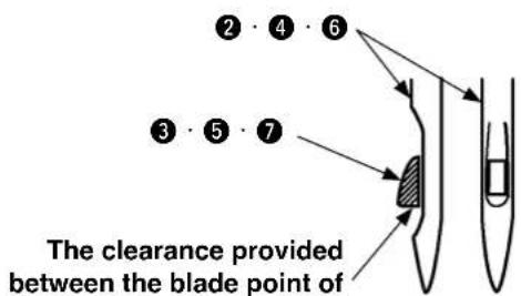
The clearance provided between the blade point of the looper and the needle should be 0 to 0.05 mm.
(6) Height adjustment of rear needle guard
1) The relationship between the middle needle ④ and the rear looper ⑤ and between the right needle ⑥ and the middle looper ⑦ is also required to assume the same conditions as (5) -1) in standard positioning.
2) Loosen the sets and move the rear needle guard base 10 vertically to adjust the height.
3) After adjustments, tighten the setscrew ⑨.
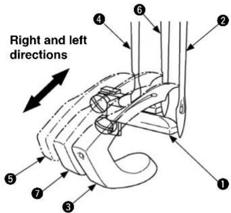
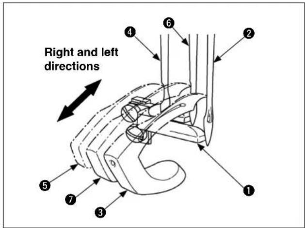
10. Adjustment of upper feed roller

WARNING :
Perform the work after turning OFF the power to prevent accidents caused by the abrupt start of the sewing machine.
(1) Adjustment of upper feed roller
1) The standard clearance is 0.08mm minimum to 0.13mm maximum between the lower position of the upper feed roller ① and the upper face of the throat plate ②.
2) The standard front/rear and right/left clearances shall be uniform between the upper feed roller ① and the feed dog ③.
3) The standard positioning of the upper feed roller ① shall be free from right and left rattling, permitting smooth movement up and down.
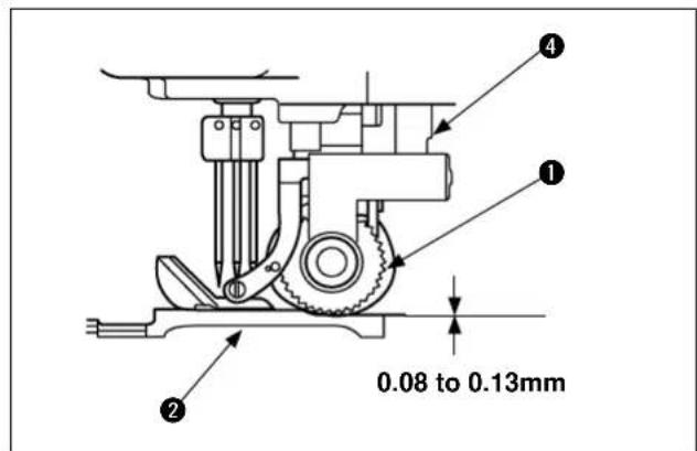
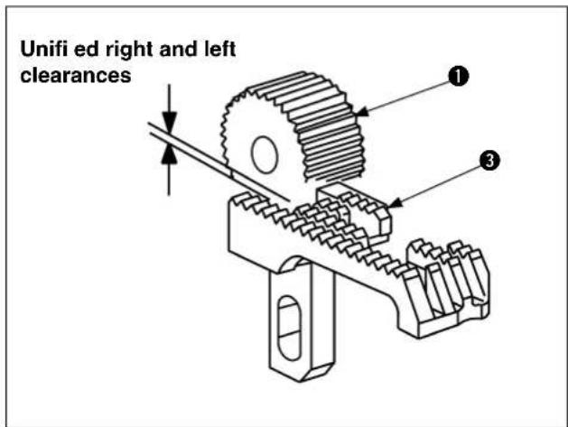
(2) Installation of upper feed roller
1) Raise the upper feed roller pressing shaft ④ and insert the upper feed roller pressing shaft ④ in the frame shaft hole of the upper feed roller frame set ⑤. Then, tighten the setscrew ⑥.
Simultaneously at that time, insert the lever connecting section ⑧ in between the roller connecting section ⑦ to join it.
2) Install the roller pressure adjusting screw ⑨.
3) Confi rm that a standard clearance (Clearance gauge: 0.08mm to 0.13mm) is secured between the upper feed roller ① and the upper face of the throat plate ②.
4) Confirm that there is proper pressure at the upper feed roller ①, enough to feed the material cloth. ☆ Pressure adjustment
○ Turning the roller pressure adjusting screw ⑨ clockwise causes the pressure to increase.
○ Turning the roller pressure adjusting screw ⑨ counterclockwise causes the pressure to decrease.
- Confir rm that the upper feed roller press-
ing shaft ④ can be raised by both hands when installing the roller pressure adjusting screw ⑨.
- If the upper feed roller
① touches the

throat plate ② and there is too much pressure, this will be a cause of cutting off the chain-off thread.
- If the clearance is too much between the
upper feed roller ① and the throat plate ②, this will be a cause of failure in supplying the chain-off thread.
- If pressure of the upper feed roller
① is
too weak for the material cloth, uneven feeding may arise.
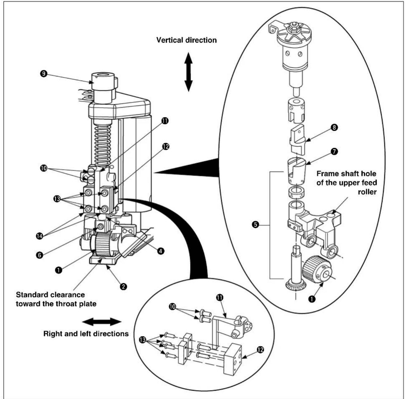
(3) Clearance adjustment between upper feed roller and throat plate
1) If the adjusted standard clearance is not correct, loosen two setscrews ⑩. Raise pressing shaft ④ to place a clearance gauge between the top face of throat plate ② and the bottom of upper feeder roller ①. Then, lower pressing shaft ④.
2) Tighten two setscrews 10 while keeping the bottom face of roller bar guide plate 11 rest on the top face of lateral guide plate 12.
3) In the state as seen from behind, confirm that the vertical clearance of the upper feed roller ① is maintained at the standard level in conjunction with the throat plate ②.
4) In the state as seen from behind, confirm that the front and rear right/left clearances on the right side of the upper feed roller ① are uniformly maintained in conjunction with the feed dog ③.
(The right/left clearance between the upper feed roller ① and the feed dog ③ shall be confirmed while)

the feed dog ③ is positioned at the highest level.
(4) Adjustment of parallelism between upper feed roller and feed dog
Loosen setscrews 10. Turning pressing shaft 4 clockwise or counterclockwise, check to be sure that an equal clearance is provided between upper feed roller 1 and the front, rear, right and left sides of feed dog 3. Then, tighten setscrews 10.
(5) Adjustment to eliminate right and left rattling in the upper feed roller
If there is a lateral play in upper feed roller 1, loosen setscrews 13 and adjust so that roller bar guide plate 11 is securely held with right and left guide plates 14, while eliminating the lateral play. Then, tighten setscrews 13.
11. Adjustment of needle thread path

WARNING : Perform the work after turning OFF the power to prevent accidents caused by the abrupt start of the sewing machine.
(1) Adjustment of needle thread path
The needle thread adjusting thread path ① is installed just under the needle thread guide ③ so that there is no sag of the needle thread that passes through the lever thread path ② from the needle thread adjusting thread path ① when the needle bar is positioned at the upper dead point.
(2) Height of needle thread adjusting path
The standard dimension from point "A" under the hole in needle thread path guide ③ to point "B" under the hole in needle thread adjusting path ① is 27 mm.
To especially tense the needle thread, adjust the distance from point "C" under the hole in needle thread path guide ③ to point "D" under the hole in needle thread adjusting path ① to approximately 36 mm.
(3) Height of needle thread support adjust plate
When the needle bar rests at its lower dead point, the standard dimension from the upper end "F" of needle thread lever thread path ② to the upper end "E" of needle thread support adjust plate ④ is 1.6 mm.
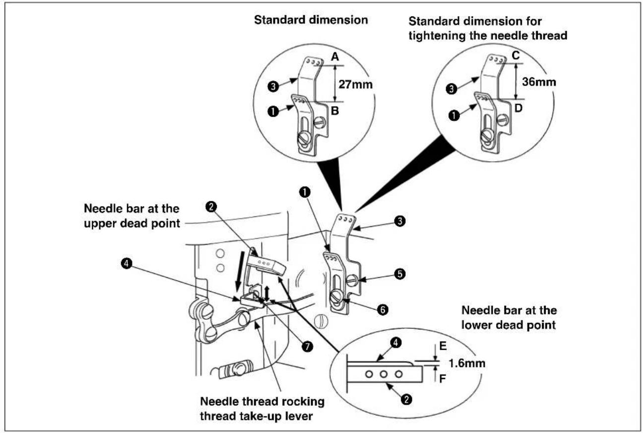
(4) Mounting position of needle thread adjusting path
1) Mount the needle thread path guide ③, and tighten the setscrew ⑤.
2) Mount the needle thread adjusting path ① in the needle thread path guide ③.
Measure the standard dimension (27mm) and tighten the setscrew 6.
○ Raising the needle thread adjusting path ① causes the needle thread to be loosened.
○ Lowering the needle thread adjusting path ① causes the needle thread to be tightened.
(5) Mounting position of needle thread support adjust plate
1) Let the lever thread path ② stay at the lower dead point.
2) Loosen two setscrews ⑦ of the needle thread support adjust plate ④ and move the needle thread support adjust plate ④ vertically. Measure the standard dimension (1.6mm) and fasten two setscrews ⑦.
○ Raising the needle thread support adjust plate ④ causes the needle thread loop to be enlarged.
○ Lowering the needle thread support adjust plate ④ causes the needle thread loop to be diminished.
1. When the two setscrews
⑦ are loosened and the needle thread support adjust plate ④ is moved to change the height of "F" and that of "E."

There is no coincidence between position of each thread path ① and that of the needle thread support adjust plate ④, this can be a cause of problems such as stitch skipping, thread breakage, and worse tightening of the needle thread.
12. Adjustment of looper thread cam

WARNING :
Perform the work after turning OFF the power to prevent accidents caused by the abrupt start of the sewing machine.
(1) Adjustment of looper thread cam
The standard positioning is secured when the pulley ① is turned counterclockwise and the first setscrew ③ of the looper thread cam ② and another first setscrew ④ of the pulley ① are aligned to the same line.

wo main shaft setscrews
④ and ⑤ of the pulley ① are turned counterclockwise, the first screw
functions as the main shaft contact setscrew 4.
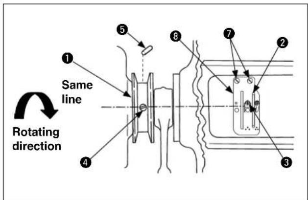
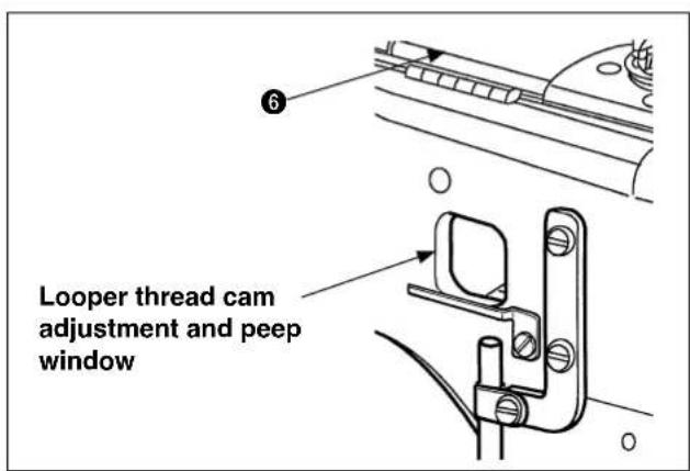
(2) Adjustment of looper thread cam
1) Open the center top cover ⑥, loosen the setscrew ⑦, and remove the cam thread path base ⑧.
2) Turn the pulley ① counterclockwise and confirm whether the first looper thread cam setscrew ③ stays on the same line with the first setscrew ④ of the pulley ①.
If the looper thread cam setscrew ③ seems to be displaced, loosen two setscrews ④ and ⑤ and turn the looper thread cam ② forward and backward for adjustment. Then, tighten the setscrew ④.
Subsequently, tighten another setscrew 5.
At the time of looper thread cam
② adjust-
ments, do not move the looper thread cam ② to the right and left.
If it is moved to the right and left, the looper thread cam ② may come in contact with the right/left side face of the cam thread path base ③ groove.
3) Install the cam thread path base ⑧ so that it does not touch the right and left faces of the looper thread cam ②. Then, tighten the setscrew ⑦.
1. The looper thread cam
② can be adjust-
ed through the peep window. However, since the inside is dark, a proper light (pen light or the like) should be used during adjustments.

- If the standard position is not secured
for the looper thread cam ②, this can be a cause of stitch skipping.
13. Adjustment of tension disk fl oating

WARNING :
Perform the work after turning OFF the power to prevent accidents caused by the abrupt start of the sewing machine.
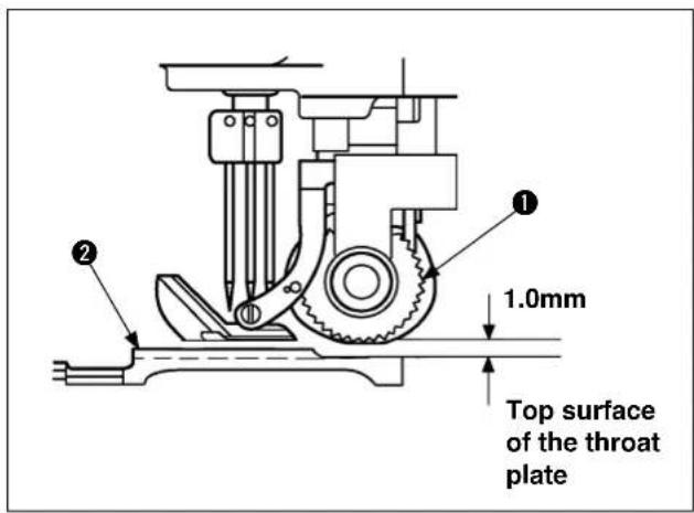
(1) Adjustment of tension disk fl oating
The standard positioning is such that tip of the disk fl oating pin ③ comes in contact with the upper tension disk ④ when the upper feed roller ① rises by 1.0mm above the upper face of the throat plate ② and that the upper tension disk ④ keeps fl oating when the upper feed roller ① rises further.
The standard size is 6.5mm between the tip of the disk floating pin③ and the upper face of the thread guide ⑤.
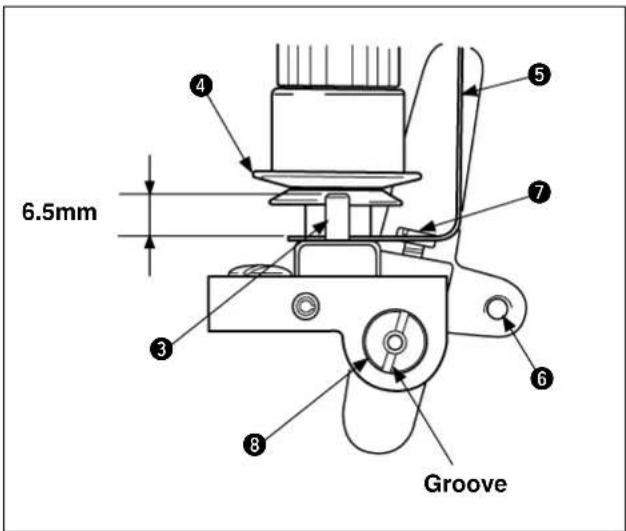
(2) Adjustment of tension disk fl oating
1) Insert a screwdriver in the groove of the tension floating shaft 8 and loosen the setscrew 7 of the lift lever 6. Then, turn the tension floating shaft 8 clockwise.
2) Adjust height of the disk floating pin ③ to 6.5mm and tighten the setscrew ⑦.

positioning is not secured for the disk fl oating pin thread cannot be pulled out when this action is needed.
③, the needle thread and/or the looper
14. Adjustment of folder

WARNING :
Perform the work after turning OFF the power to prevent accidents caused by the abrupt start of the sewing machine.
(1) Folder mounting position
Insert the slide base ③ of the folder set ② in the center of the slide plate ① of the right and left cylinder arms, and slide the presser ④ in forward direction. At that time, a standard clearance of 0.8mm to 1.6mm should be secured between the front section "A" of the presser ④ and the outlet section "B" of the upper folder ⑤.
If Section "B" of the upper folder
⑤ is installed as closer as possible to Section "A" of the presser ④

, the result of sewing tends to be more stabilized for the material to be sewn. In such a case, however, it is necessary to make sure not to let the upper folder ⑤ come in contact with the presser ④ in the middle of sewing.
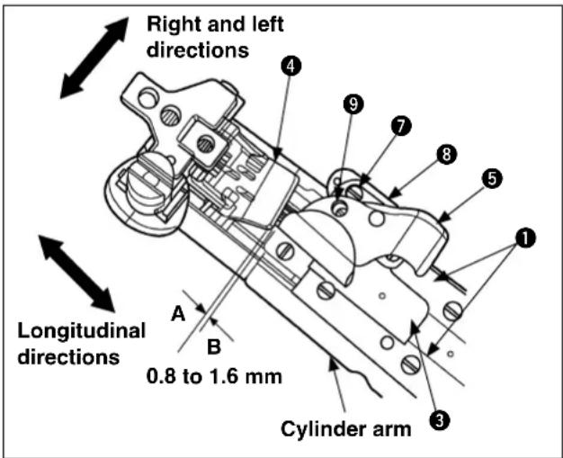
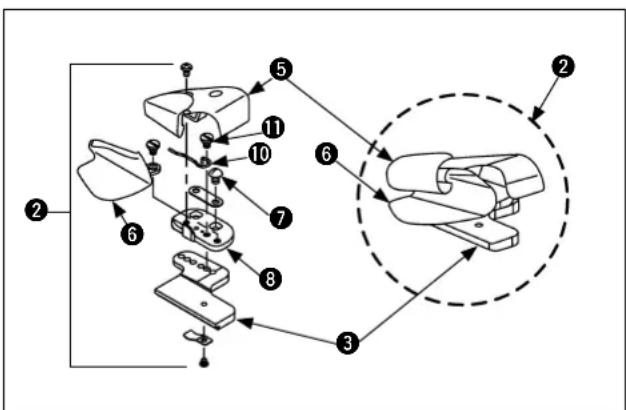
(2) Adjustment of folder mounting position
1) When the folder set ② is installed, confirm whether a standard clearance is secured between the front section "A" of the presser ④ and the outlet section "B" of the upper folder ⑤.
If the conditions seem to be awkward in regard to the front and rear contact between the front section "A" of the presser ④ and the outlet section "B" of the upper folder ⑤ and right and left positioning of the upper and lower folders (⑤ and ⑥), loosen two setscrews ⑦ and adjust front/rear and right/left positioning of the folder base ⑧.
2) If it is necessary to adjust the outlet at the tips of the upper and lower folders ( ⑤ and ⑥ ), loosen two setscrews ⑨ and make adjustments by moving the tip of the upper folder ⑤ to the right and left.
To widen the outlets of the upper and lower folders (⑤ and ⑥), move the tip of the upper folder ⑤ to the left.
To narrow the outlets of the upper and lower folders (⑤ and ⑥), move the tip of the upper folder ⑤ to the right.
3) The spring is fastened to the right side section of the lower folder 6 by means of the setscrew 11.
The tip section of the lower folder ⑥ is devised to have an escape recess somewhat to the right so that an extra-heavyweight material can be duly handled.
1. According to the thickness of a material
to be sewn, adjust the upper and lower folders (⑤ and ⑥).
In addition, for the kinds of folder sets
2,

there are folder sets ② other than the standard folder.
Refer to "14. (3) Folder types".
2. If positioning of the folder set
② is inac-
curate, the quality of the sewn product will be lowered.
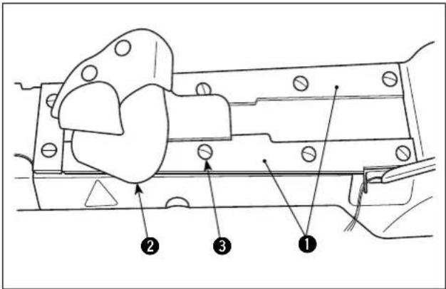
Insert folder ② into folder support ①. After insertion, loosen setscrews ③ (eight setscrews for sewing with the differential feed or six ones for sewing without the differential feed) to adjust so that the folder slides smoothly with no play.
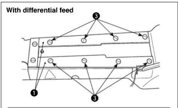
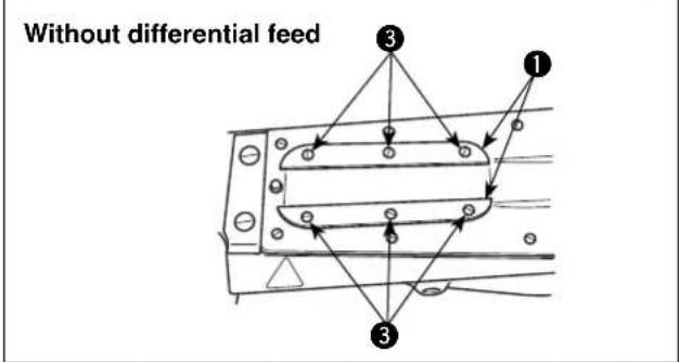
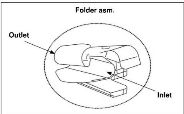
(3) Folder types
Select an optimal folder according to nature, thinness, and thickness of the material cloth.
| No. | JUKI part No. : US part | No. : Outlet dimensions | Folder features | |
| 1 40 | 066942 | 24502502(23420AY18-1/8) | 3.2mm | A standard type provided with a spring, suitable for a product that has step sections in the material cloth.(Stanadard) |
| 2 40 | 072322 | 24517104(23420AY18-3/22) | 2.4mm | Same as the standard type. The outlet section at the folder tip is narrow, and suitable for medium-weight materials. |
| 3 40 | 072324 | 24620205(23420AY18-5/32) | 4.0mm | Same as the standard type. The outlet section at the folder tip is wide, and suitable for extraheavyweight materials. |
| 4 40 | 072328 | 24503005(23420Z-9-1/8) | 3.2mm | The folder tip section is shorter than that of the standard type. Functionally same. A shorter type assures easier control of materials. |
15. Cleaning the sewing machine head

WARNING :
Perform the work after turning OFF the power to prevent accidents caused by the abrupt start of the sewing machine.
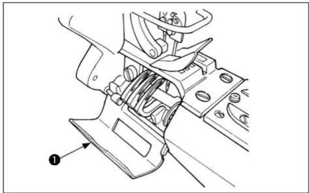
natural_image
Technical line drawing of a mechanical assembly with no visible text or symbols1) Be sure to remove cloth chips from around the looper before they accumulate.
Open looper cover ①. Remove cloth chips accumulated around the looper with tweezers.
If cloth chips which accumulate around the
looper are left without being removed, they are more likely to enter inside the sewing machine.
Ingress of cloth chips into the inner section of

the sewing machine can cause the oil tank fi l- ter to be clogged earlier than usual, leading to faulty oiling. Such a phenomenon can eventually cause abnormal abrasion or seizure of the sewing machine components.
So, be extremely careful not to leave cloth chips around the looper.
2) Periodically remove cloth chips accumulated in the filter.
As a guide, cleaning is necessary when the amount of oil splashing against the oil circulation identification window decreases. If splash of oil is not observed, even for a second, at the time of startup of the sewing machine, be sure to remove cloth chips from the filter.

ving machine is kept being driven after oil splashing has stopped, the oil pipe will be clogged with cloth chips. This eventually disables oiling. If such a trouble occurs, entire cleaning of the inside of the pipe is required. So, be extremely careful.
Sewing machine head with the differential feed mechanism
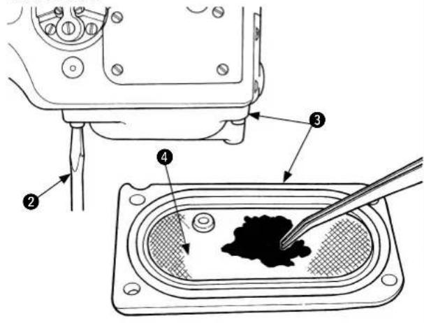
3) The filter cleaning procedure differs by the type of sewing machine head, i.e., the sewing machine head provided with the differential feed mechanism and the one without it.
Be sure to drain the oil from the machine head before starting cleaning.
[For the sewing machine head with the differential feed mechanism]
Remove four screws with screwdriver tank ③. Remove oil
Remove cloth chips from the top of fi Iter ④. At this time, as fi Iter is detachable, remove cloth chips also from inside oil tank ③. After the completion of cleaning, re-tighten the four screws to secure the fi Iter.
Sewing machine head without the differential feed mechanism 6
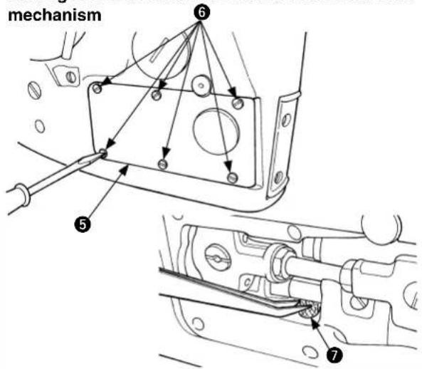
[For the sewing machine head without the differential feed mechanism]
Remove cylinder side cover ⑤. Remove six setscrews ⑥.
Then, f7 can be observed inside the sewing machine. Remove cloth chips which have adhered on the filter with tweezers. After the completion of cleaning, re-secure cylinder side cover 5.
* This procedure applies to the sewing machine mounted with part ④ (No. 40067058 (+40067056)) or part ⑦ (No. 40098071 (+EA9500B0000)). Those parts can be mounted on the sewing machine which is not provided with them.
V. TROUBLES AND CORRECTIVE MEASURES
| Check and corrective measuresTrouble Cause (1) ( | |||
| 1. Thread breakage 1-1) Threading | 1-A) Thread jamming at thread guide, threading error | Refer to "Ⅲ-5. How to conduct threading". | |
| 1-2) Thread path | 2-A) Flaws, burrs, rust generation, and the like can be a cause of resistance in operation if they are present in needles, throat plate, small thread tension, needle thread rocking thread path, needle thread guide thread path, lower looper, looper thread guide pipe, looper thread cam, lower thread path guide, and thread tension disc. | Take measures to remove flaws, burrs, etc., and fi nish the thread path neatly. In this case, however, the lower looper, throat plate, looper thread cam, and such important parts should be replaced if their shapes seem to have changed. | |
| 1-3) Rear needle guard | 3-A) If contact between the needle and rear needle guard is excessive, needle grooves are created on he rear needle guard, resulting in thread cut. | Replace the needle, and replace the part if the rear needle guard is worn. | |
| 1-4) Needle | 4-A) The needle is too thin for the thread that is now used. | Use an appropriate needle. | |
| 1-5) Needle heat Reduce the needle size. Reduce the because of heated needle depen ding on the material type, the number of superimposed materials, and sewing speed. | sewing speed. Use needle cooling air. | ||
| 1-6) Thread 6-A) | Poor quality of the thread | Use a high-quality thread. | |
| 1-7) Thread tension 7-A) | Excessive thread tension | Reduce the thread tension. Thread tension is excessive because the needle thread adjusting thread path has been lowered too much. | |
| 1-8) Contact Set the lower roller in the lower position. | |||
| 1-9) Idle loop error Set the lower location in the upper position between needle and looper timing. Position of the looper thread cam is inadequate. Clearance is too much between the upper feed roller and the upper face of the throat plate. | |||
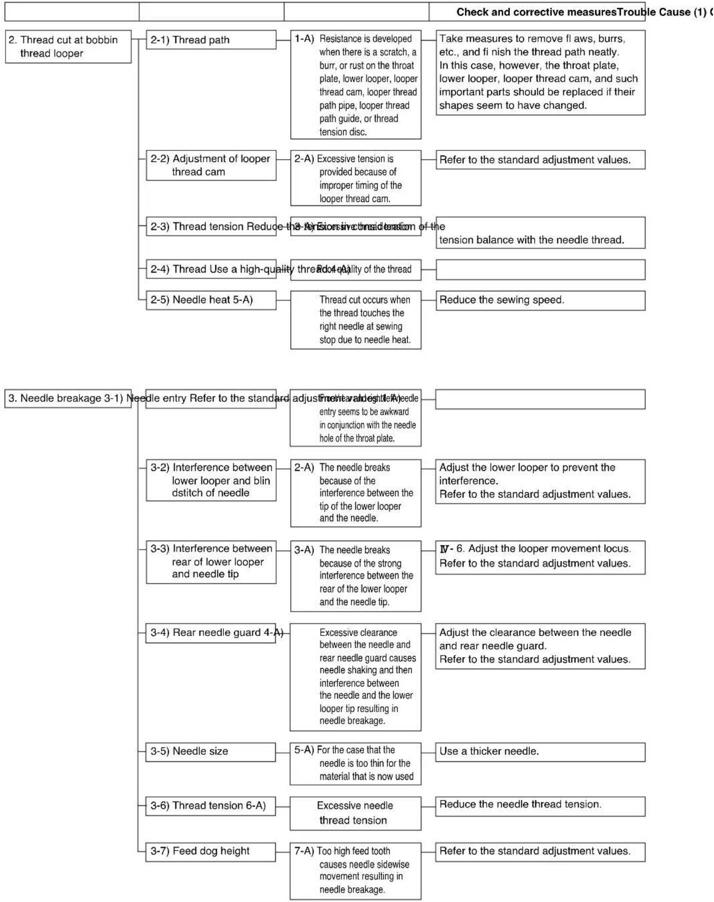
flowchart
graph TD
    A["2. Thread cut at bobbin thread looper"] --> B["2-1) Thread path"]
    B --> C["1-A) Resistance is developed when there is a scratch, a burr, or rust on the throat plate, lower looper, loop thread cam, loop thread path pipe, loop thread path guide, or thread tension disc."]
    C --> D["Take measures to remove fl aws, burrs, etc., and fi nish the thread path neatly. In this case, however, the throat plate, lower looper, loop thread cam, and such important parts should be replaced if their shapes seem to have changed."]
    A --> E["2-2) Adjustment of looper thread cam"]
    E --> F["2-A) Excessive tension is provided because of improper timing of the looper thread cam."]
    F --> G["Refer to the standard adjustment values."]
    A --> H["2-3) Thread tension Reduce the 3-4) Excessive tension reduction of the tension balance with the needle thread."]
    H --> I["2-4) Thread Use a high-quality thread (A) Quality of the thread"]
    I --> J["Red 4-A) Thread cut occurs when the thread touches the right needle at sewing stop due to needle heat."]
    A --> K["2-5) Needle heat 5-A)"]
    K --> L["Thread cut occurs when the thread touches the right needle at sewing stop due to needle heat."]
    L --> M["Reduce the sewing speed."]

    N["3. Needle breakage 3-1) Needle entry Refer to the standard adjustment value of 1-A needle entry seems to be awkward in conjunction with the needle hole of the throat plate."]
    N --> O["3-2) Interference between lower looper and blind stitch of needle"]
    O --> P["2-A) The needle breaks because of the interference between the tip of the lower looper and the needle."]
    P --> Q["Adjust the lower looper to prevent the interference. Refer to the standard adjustment values."]
    N --> R["3-3) Interference between rear of lower looper and needle tip"]
    R --> S["3-A) The needle breaks because of the strong interference between the rear of the lower looper and the needle tip."]
    S --> T["IV-6). Adjust the looper movement locus. Refer to the standard adjustment values."]
    N --> U["3-4) Rear needle guard 4-A"]
    U --> V["Excessive clearance between the needle and rear needle guard causes needle shaking and then interference between the needle and the lower looper tip resulting in needle breakage."]
    V --> W["Adjust the clearance between the needle and rear needle guard. Refer to the standard adjustment values."]
    N --> X["3-5) Needle size"]
    X --> Y["5-A) For the case that the needle is too thin for the material that is now used"]
    Y --> Z["Use a thicker needle."]
    N --> AA["3-6) Thread tension 6-A"]
    AA --> AB["Excessive needle thread tension"]
    AB --> AC["Reduce the needle thread tension."]
    N --> AD["3-7) Feed dog height"]
    AD --> AE["7-A) Too high feed tooth causes needle sidewise movement resulting in needle breakage."]
    AE --> AF["Refer to the standard adjustment values."]
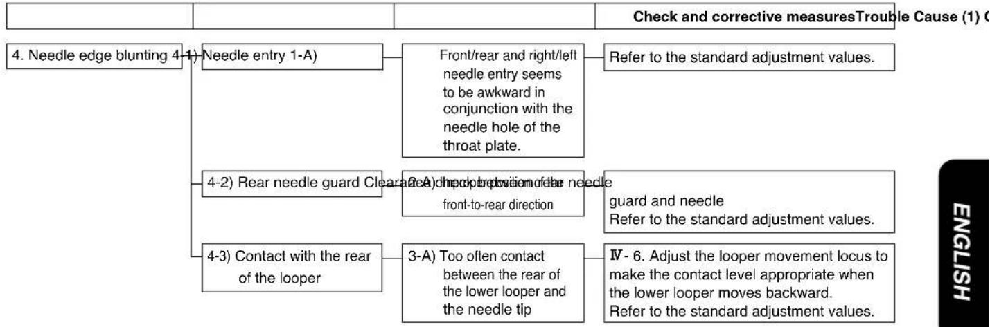
flowchart
graph TD
    A["4. Needle edge blunting 4-1) Needle entry 1-A"] --> B["Front/rear and right/left needle entry seems to be awkward in conjunction with the needle hole of the throat plate."]
    A --> C["4-2) Rear needle guard Clear at 2A"] --> D["A side motion of the needle front-to-rear direction"]
    A --> E["4-3) Contact with the rear of the looper"]
    E --> F["3-A) Too often contact between the rear of the lower looper and the needle tip"]
    B --> G["Refer to the standard adjustment values."]
    D --> H["guard and needle Refer to the standard adjustment values."]
    F --> I["IV - 6. Adjust the looper movement locus to make the contact level appropriate when the lower looper moves backward. Refer to the standard adjustment values."]
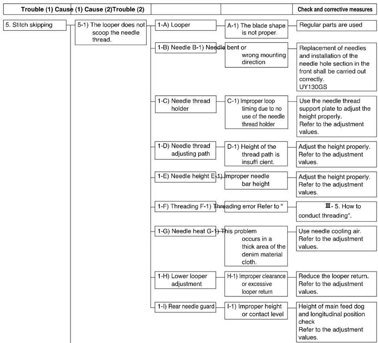
flowchart
graph TD
    A["Trouble (1) Cause (1) Cause (2) Trouble (2)"] --> B["5. Stitch skipping"]
    B --> C["5-1) The looper does not scoop the needle thread."]
    C --> D["1-A) Looper"]
    D --> E["A-1) The blade shape is not proper."]
    E --> F["Regular parts are used"]
    C --> G["1-B) Needle B-1) Needle bent or wrong mounting direction"]
    G --> H["Replacement of needles and installation of the needle hole section in the front shall be carried out correctly. UY130GS"]
    C --> I["1-C) Needle thread holder"]
    I --> J["C-1) Improper loop timing due to no use of the needle thread holder"]
    J --> K["Use the needle thread support plate to adjust the height properly. Refer to the adjustment values."]
    C --> L["1-D) Needle thread adjusting path"]
    L --> M["D-1) Height of the thread path is insufficient."]
    M --> N["Adjust the height properly. Refer to the adjustment values."]
    C --> O["1-E) Needle height E-1) Improper needle bar height"]
    O --> P["Adjust the height properly. Refer to the adjustment values."]
    C --> Q["1-F) Threading F-1) Threading error Refer to ""]
    Q --> R["Ⅲ - 5. How to conduct threading"."]
    C --> S["1-G) Needle heat G-1) This problem occurs in a thick area of the denim material cloth."]
    S --> T["Use needle cooling air. Refer to the adjustment values."]
    C --> U["1-H) Lower looper adjustment"]
    U --> V["H-1) Improper clearance or excessive looper return"]
    V --> W["Reduce the looper return. Refer to the adjustment values."]
    C --> X["1-I) Rear needle guard"]
    X --> Y["I-1) Improper height or contact level"]
    Y --> Z["Height of main feed dog and longitudinal position check. Refer to the adjustment values."]
To the next page
| Trouble (1) Cause | (1) Cause (2) Trouble (2) | Check and corrective measures |
From the previous page
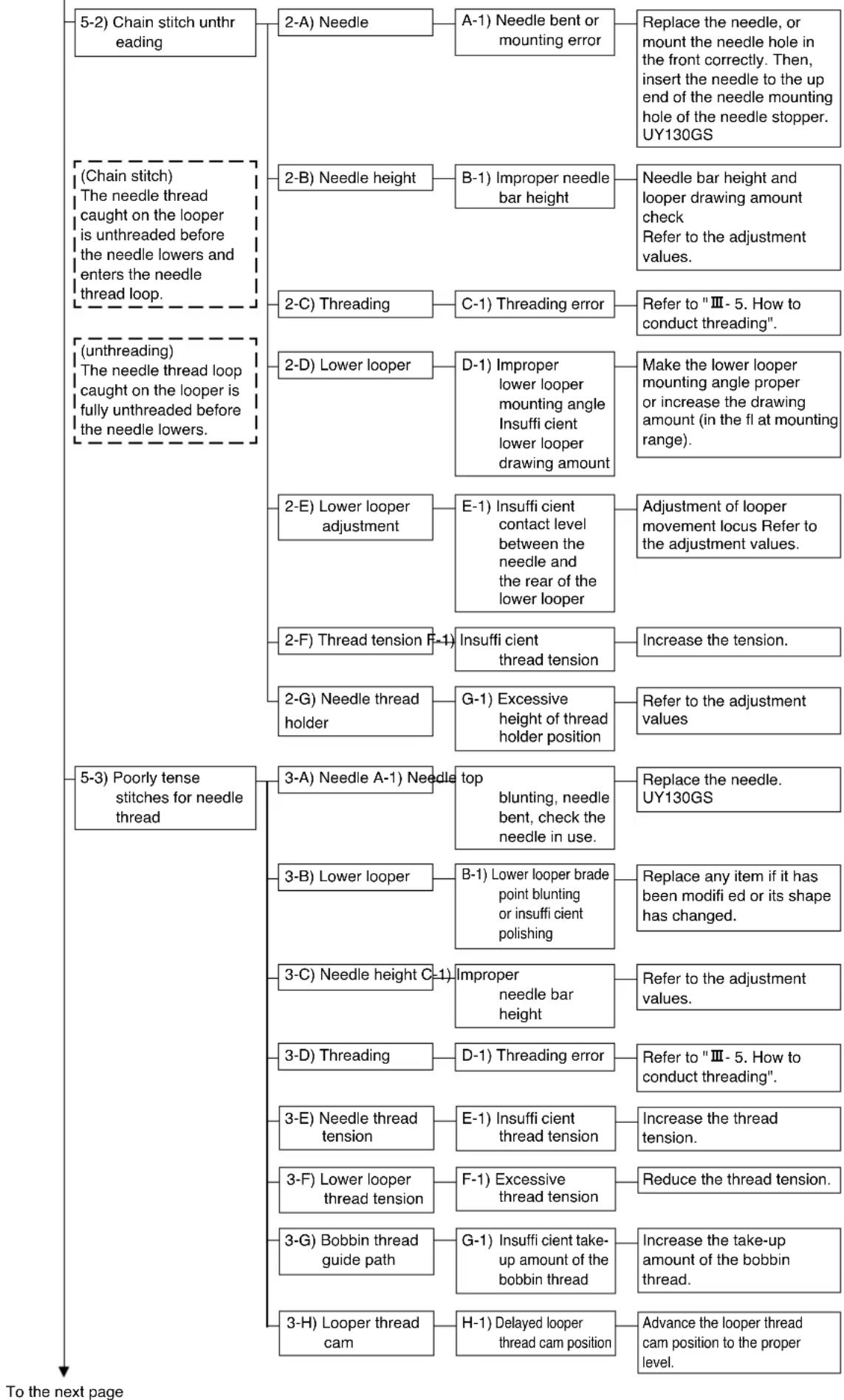
flowchart
graph TD
    A["5-2) Chain stitch unthreading"] --> B["2-A) Needle"]
    B --> C["A-1) Needle bent or mounting error"]
    C --> D["Replace the needle, or mount the needle hole in the front correctly. Then, insert the needle to the up end of the needle mounting hole of the needle stopper. UY130GS"]
    A --> E["(Chain stitch) The needle thread caught on the looper is unthreaded before the needle lowers and enters the needle thread loop."]
    E --> F["2-B) Needle height"]
    F --> G["B-1) Improper needle bar height"]
    G --> H["Needle bar height and looper drawing amount check Refer to the adjustment values."]
    E --> I["(unthreading) The needle thread loop caught on the looper is fully unthreaded before the needle lowers."]
    I --> J["2-C) Threading"]
    J --> K["C-1) Threading error"]
    K --> L["Refer to "Ⅲ- 5. How to conduct threading"."]
    I --> M["(5-3) Poorly tense stitches for needle thread"]
    M --> N["2-D) Lower looper"]
    N --> O["D-1) Improper lower looper mounting angle Insuffi cient lower looper drawing amount"]
    O --> P["Make the lower looper mounting angle proper or increase the drawing amount (in the fl at mounting range)."]
    M --> Q["2-E) Lower looper adjustment"]
    Q --> R["E-1) Insuffi cient contact level between the needle and the rear of the lower looper"]
    R --> S["Adjustment of looper movement locus Refer to the adjustment values."]
    M --> T["2-F) Thread tension F-1"]
    T --> U["Insuffi cient thread tension"]
    U --> V["Increase the tension."]
    M --> W["2-G) Needle thread holder"]
    W --> X["G-1) Excessive height of thread holder position"]
    X --> Y["Refer to the adjustment values"]
    M --> Z["3-A) Needle A-1) Needle top blunting, needle bent, check the needle in use."]
    Z --> AA["Replace the needle. UY130GS"]
    M --> AB["3-B) Lower looper"]
    AB --> AC["B-1) Lower looper brade point blunting or insuffi cient polishing"]
    AC --> AD["Replace any item if it has been modifi ed or its shape has changed."]
    M --> AE["3-C) Needle height C-1"]
    AE --> AF["Improper needle bar height"]
    AF --> AG["Refer to the adjustment values."]
    M --> AH["3-D) Threading"]
    AH --> AI["D-1) Threading error"]
    AI --> AJ["Refer to "Ⅲ- 5. How to conduct threading"."]
    M --> AK["3-E) Needle thread tension"]
    AK --> AL["E-1) Insuffi cient thread tension"]
    AL --> AM["Increase the thread tension."]
    M --> AN["3-F) Lower looper thread tension"]
    AN --> AO["F-1) Excessive thread tension"]
    AO --> AP["Reduce the thread tension."]
    M --> AQ["3-G) Bobbin thread guide path"]
    AQ --> AR["G-1) Insuffi cient take-up amount of the bobbin thread"]
    AR --> AS["Increase the take-up amount of the bobbin thread."]
    M --> AT["3-H) Looper thread cam"]
    AT --> AU["H-1) Delayed looper thread cam position"]
    AU --> AV["Advance the looper thread cam position to the proper level."]
| Trouble (1) Cause (1) Cause (2) Trouble (2) | Check and corrective measures |
From the previous page
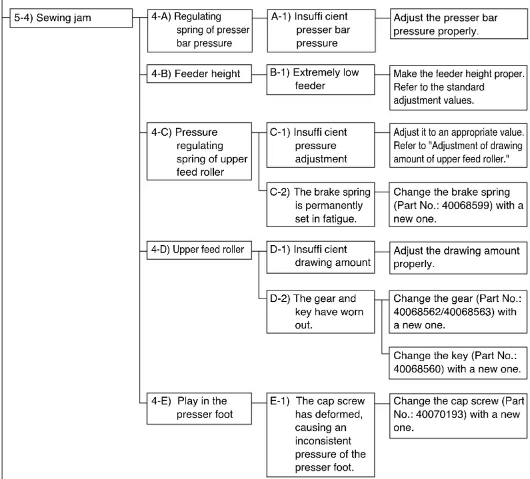
flowchart
graph TD
    A["5-4) Sewing jam"] --> B["4-A) Regulating spring of presser bar pressure"]
    A --> C["4-B) Feeder height"]
    A --> D["4-C) Pressure regulating spring of upper feed roller"]
    A --> E["4-D) Upper feed roller"]
    A --> F["4-E) Play in the presser foot"]

    B --> G["A-1) Insuffi cient presser bar pressure"]
    G --> H["Adjust the presser bar pressure properly."]
    C --> I["B-1) Extremely low feeder"]
    I --> J["Make the feeder height proper. Refer to the standard adjustment values."]
    D --> K["C-1) Insuffi cient pressure adjustment"]
    K --> L["Adjust it to an appropriate value. Refer to "Adjustment of drawing amount of upper feed roller.""]
    D --> M["C-2) The brake spring is permanently set in fatigue."]
    M --> N["Change the brake spring (Part No.: 40068599) with a new one."]
    E --> O["D-1) Insuffi cient drawing amount"]
    O --> P["Adjust the drawing amount properly."]
    E --> Q["D-2) The gear and key have worn out."]
    Q --> R["Change the gear (Part No.: 40068562/40068563) with a new one."]
    Q --> S["Change the key (Part No.: 40068560) with a new one."]
    F --> T["E-1) The cap screw has deformed, causing an inconsistent pressure of the presser foot."]
    T --> U["Change the cap screw (Part No.: 40070193) with a new one."]
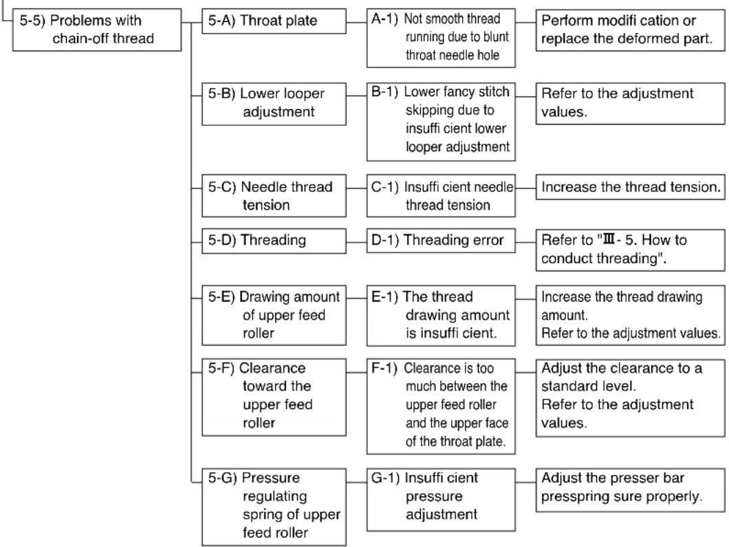
flowchart
graph TD
    A["5-5) Problems with chain-off thread"] --> B["5-A) Throat plate"]
    B --> C["A-1) Not smooth thread running due to blunt throat needle hole"]
    C --> D["Perform modification or replace the deformed part."]
    A --> E["5-B) Lower looper adjustment"]
    E --> F["B-1) Lower fancy stitch skipping due to insufficient client lower looper adjustment"]
    F --> G["Refer to the adjustment values."]
    A --> H["5-C) Needle thread tension"]
    H --> I["C-1) Insufficient client needle thread tension"]
    I --> J["Increase the thread tension."]
    A --> K["5-D) Threading"]
    K --> L["D-1) Threading error"]
    L --> M["Refer to "III - 5. How to conduct threading"."]
    A --> N["5-E) Drawing amount of upper feed roller"]
    N --> O["E-1) The thread drawing amount is insufficient client."]
    O --> P["Increase the thread drawing amount. Refer to the adjustment values."]
    A --> Q["5-F) Clearance toward the upper feed roller"]
    Q --> R["F-1) Clearance is too much between the upper feed roller and the upper face of the throat plate."]
    R --> S["Adjust the clearance to a standard level. Refer to the adjustment values."]
    A --> T["5-G) Pressure regulating spring of upper feed roller"]
    T --> U["G-1) Insufficient client pressure adjustment"]
    U --> V["Adjust the presser bar presspring sure properly."]
VI. DRAWING OF THE TABLE
JUKI Part No.: 40107535 (separately available)
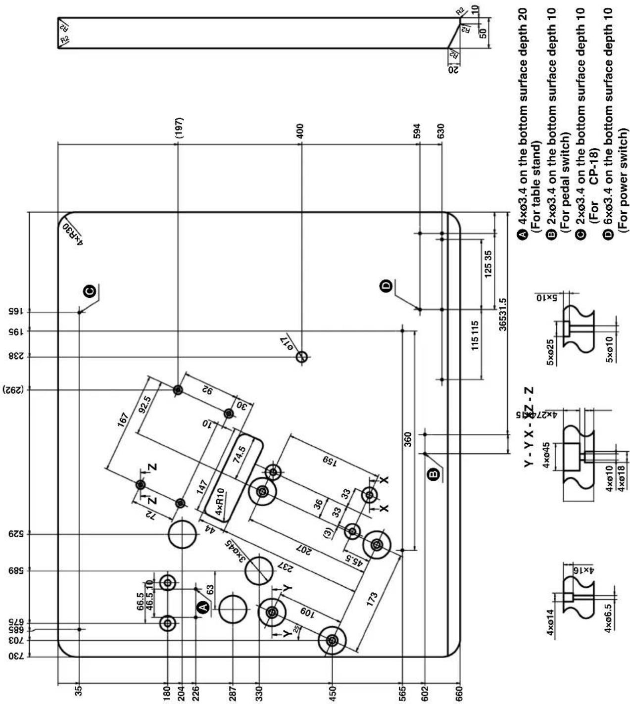
VII. TABLE MACHINING DIAGRAM (only for the sewing machine provided with a clutch motor)
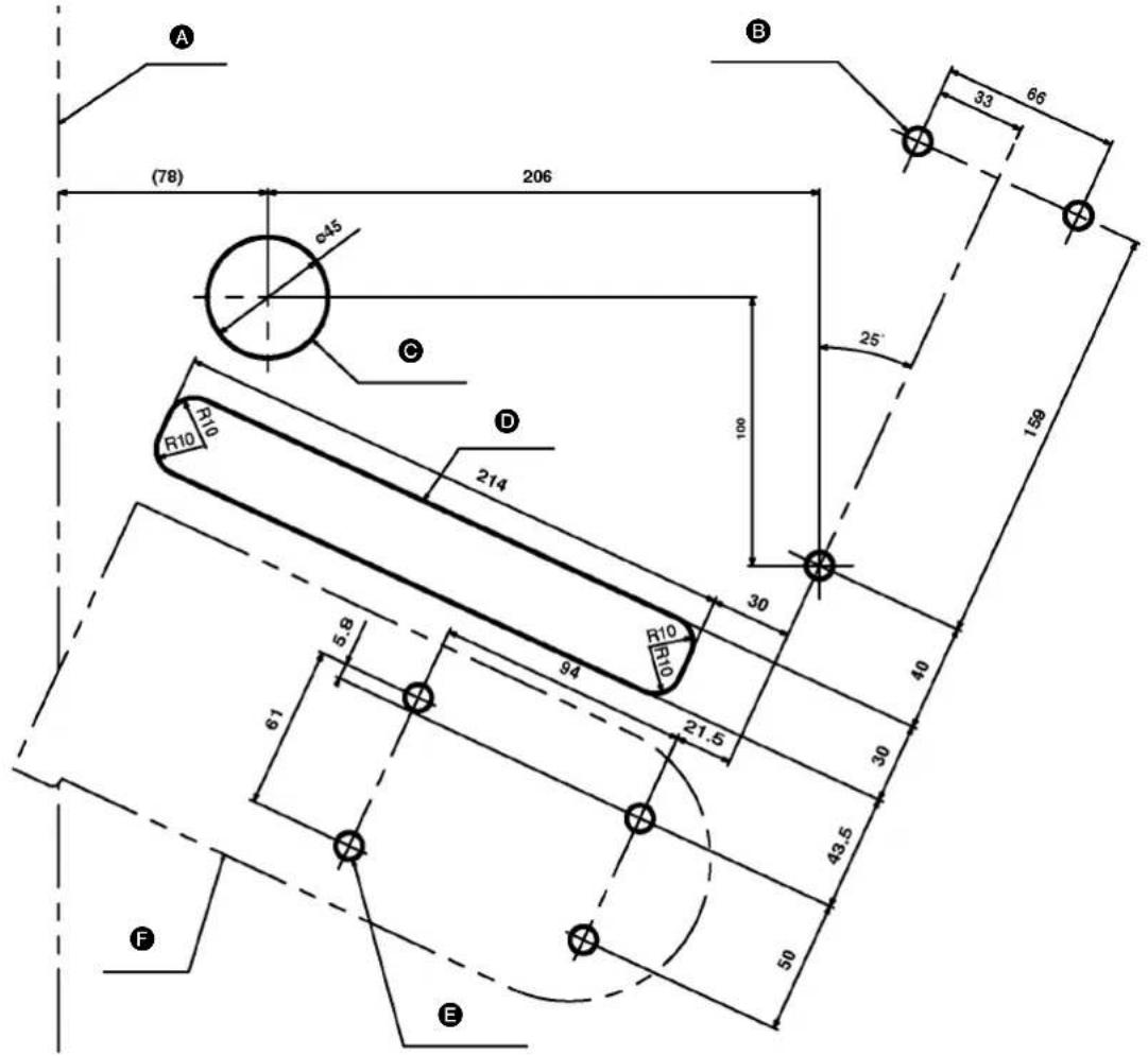
A End face of table
B Clutch-motor mounting location (3 x φ10)
© Through-hole for chain of presser foot lifting pedal
D Belt clearance groove
E Mount base mounting hole (4 x φ10)
F Mount base (Note)
(Note) The JUKI exclusive mounting base is regarded as a product with the model name "MT05."
The above table is the table machining drawing using the MT05.
It should be noted, however, that only one cushion rubber is to be used though the MT05 is provided with two of them. Mounting screws and washers are supplied with the mount base.
* Mounting screw SM6087002 TN (M8) 4 pcs/; Washer WP0841600SC 4 pcs.
DEUTSCH
natural_image
Line drawing of hands assembling a handheld electronic device (no text or symbols visible)natural_image
Technical line drawing of a mechanical assembly with hands operating a tool (no text or symbols present)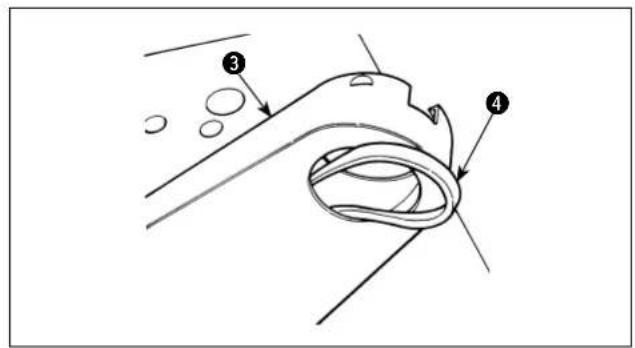
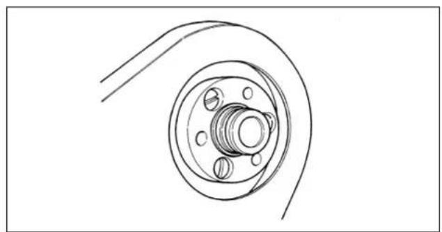
natural_image
Technical line drawing of a mechanical component with concentric rings and mounting holes (no text or symbols)
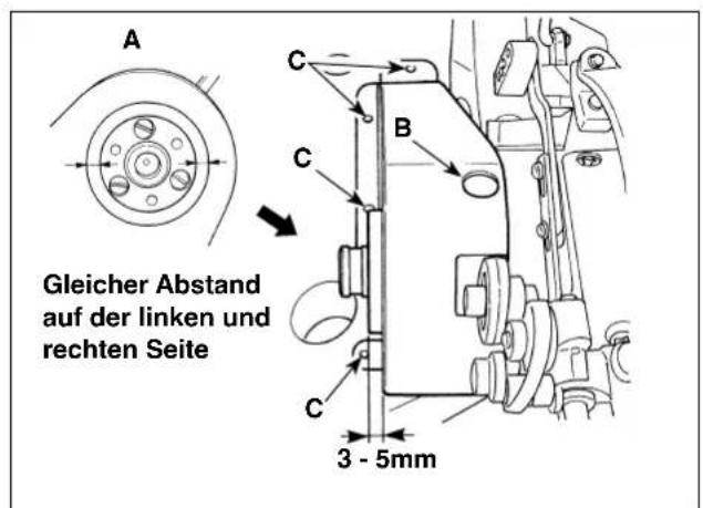

natural_image
Technical line drawing of a mechanical assembly with gears and levers (no text or symbols)(2) Ohne Differentialtransportt (MS-3580SF/0SN)

natural_image
Technical line drawing of a mechanical assembly with no visible text or symbolsnatural_image
Technical line drawing of a mechanical assembly with no visible text or symbols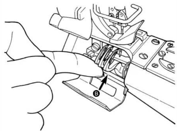
natural_image
Technical line drawing of a mechanical assembly with a hand adjusting a component (no text or symbols visible)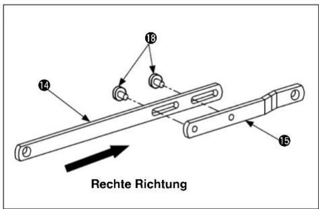
natural_image
Mechanical assembly diagram showing a gear and shaft assembly (no text or labels)natural_image
Technical line drawing of a mechanical assembly with springs and gears (no text or symbols)natural_image
Technical line drawing of a mechanical assembly with no visible text or symbolsnatural_image
Technical line drawing of a mechanical clamp or clamping device (no text or symbols)natural_image
Technical line drawing of a mechanical assembly with bolts and a central housing (no text or symbols)natural_image
Mechanical assembly diagram showing a rotating component with a directional arrow indicating motion (no text or symbols present)natural_image
Technical line drawing of a mechanical device with no visible text or symbols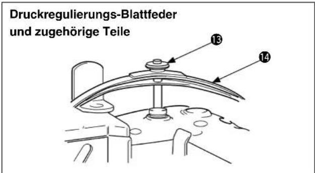
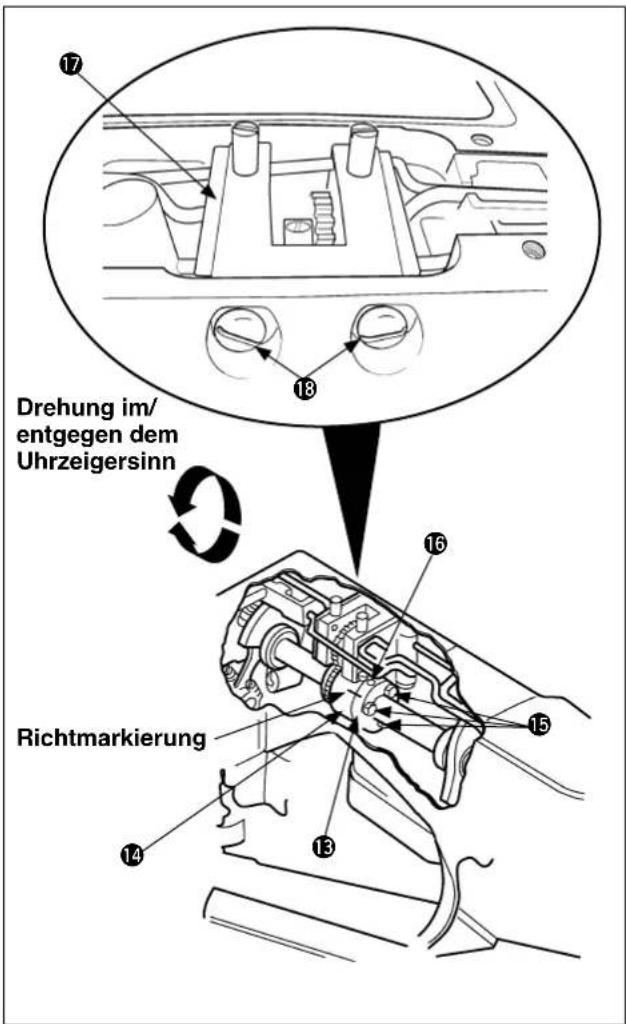
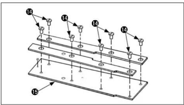

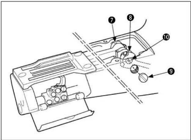
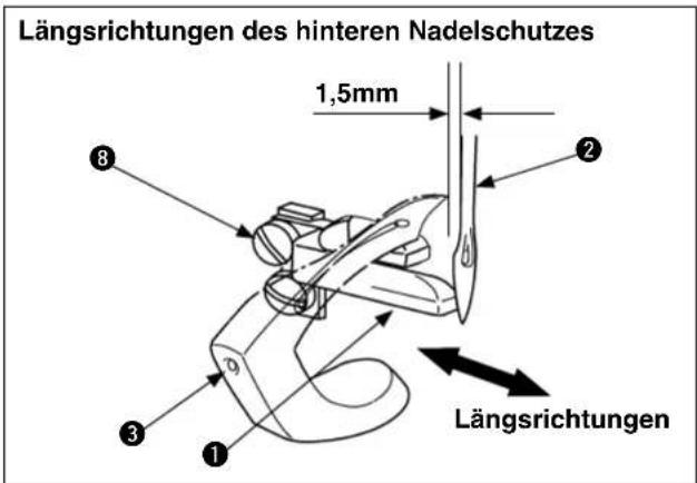
WARNING : Perform the work after turning OFF the power to prevent accidents caused by the abrupt start of the sewing machine.
natural_image
Technical line drawing of a mechanical component with no visible text or symbolsnatural_image
Technical line drawing of a mechanical bracket or clamp assembly (no text or symbols)natural_image
Technical line drawing of a mechanical assembly with no visible text or symbolsnatural_image
Line drawing of hands assembling a handheld electronic device (no text or symbols visible)natural_image
Technical line drawing of a mechanical assembly with hands operating a component (no text or symbols)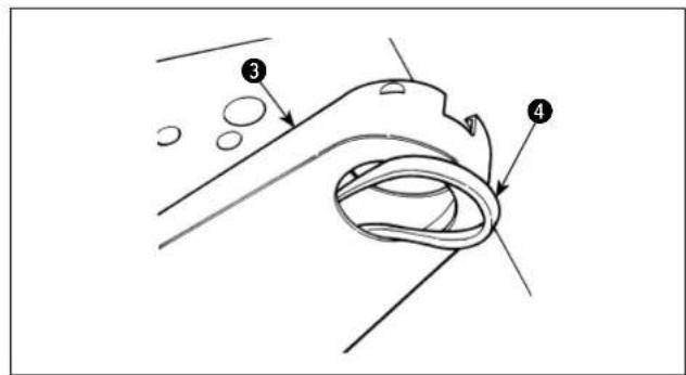
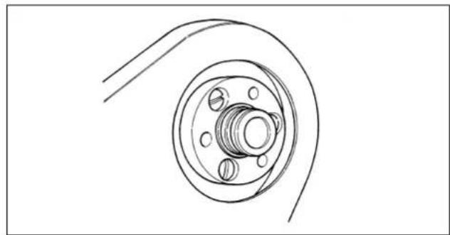
natural_image
Technical line drawing of a mechanical component with concentric rings and mounting holes (no text or symbols)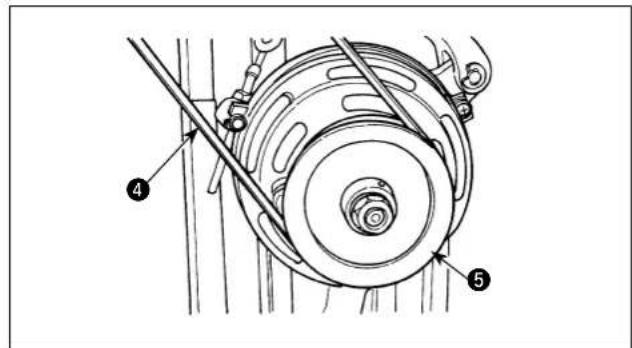
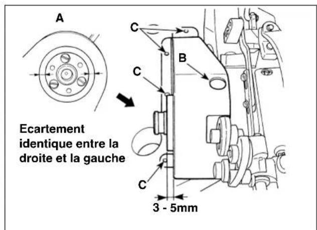
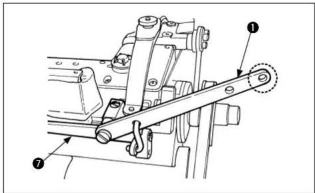
natural_image
Technical line drawing of a mechanical assembly with no visible text or symbolsnatural_image
Technical line drawing of a sewing machine with no visible text or symbolsnatural_image
Technical line drawing of a mechanical assembly with gears and levers (no text or symbols)natural_image
Technical line drawing showing mechanical assembly before and after transformation (no text or symbols)
natural_image
Technical line drawing of a mechanical assembly with a hand operating a component (no text or symbols visible)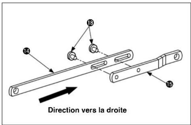
natural_image
Technical line drawing of a mechanical assembly with gears and shafts (no text or symbols)natural_image
Technical line drawing of a mechanical assembly with springs and gears (no text or symbols)natural_image
Technical line drawing of a mechanical assembly with no visible text or symbolsnatural_image
Technical line drawing of a mechanical clamp or clamping device (no text or symbols)natural_image
Technical line drawing of a mechanical assembly with springs and a central hub (no text or symbols)natural_image
Mechanical assembly diagram showing a pulley and lever mechanism (no text or labels)natural_image
Technical line drawing of a mechanical device with no visible text or symbols
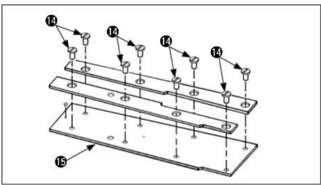
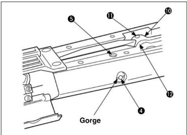
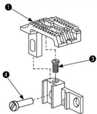

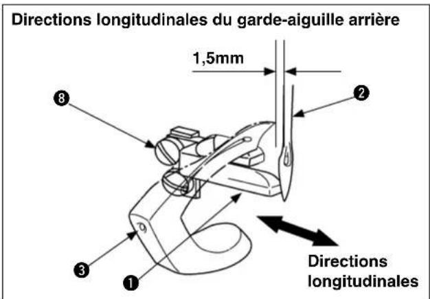
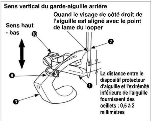
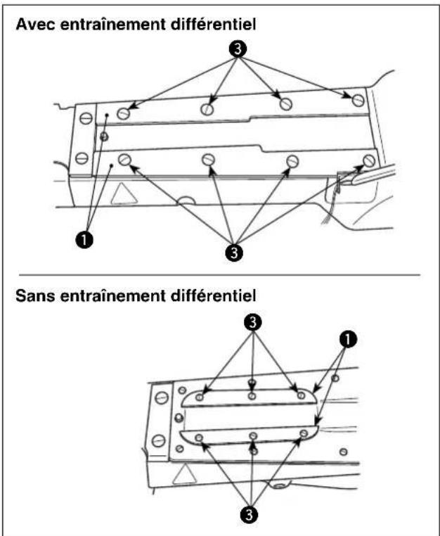
natural_image
Technical line drawing of a mechanical assembly with no visible text or symbols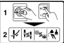
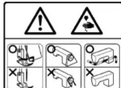
V. PROBLEMAS Y MEDIDAS CORRECTIVAS 47
VI. DIBUJO DE LA MESA 53
natural_image
Line drawing of hands assembling a handheld electronic device (no text or symbols visible)natural_image
Technical line drawing of a mechanical assembly with hands operating a component (no text or symbols)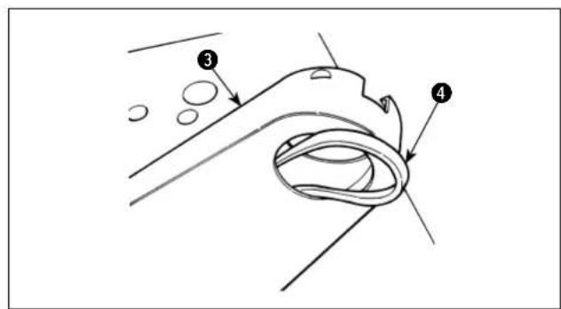

natural_image
Technical line drawing of a mechanical component with concentric rings and mounting holes (no text or symbols)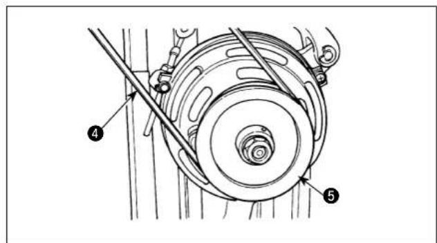
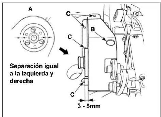
Aplique la grasa (Pieza No.: 40013640),

① Cjto. de embrague
② Vástago del embrague
3 Palanca del embrague
natural_image
Technical line drawing of a mechanical assembly with no visible text or symbolsnatural_image
Technical line drawing of a mechanical assembly with gears and levers (no text or symbols)natural_image
Technical line drawing of a mechanical assembly with no visible text or symbolsnatural_image
Technical line drawing of a mechanical assembly with spring and mounting bracket (no text or symbols)
natural_image
Technical line drawing of a mechanical assembly with a hand pointing to a component (no text or symbols present)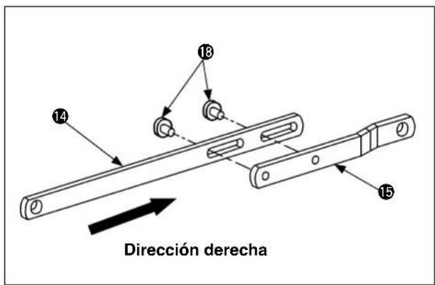
natural_image
Mechanical assembly diagram showing a gear and shaft assembly (no text or labels)natural_image
Technical line drawing of a mechanical assembly with springs and gears (no text or symbols)natural_image
Technical line drawing of a mechanical assembly with no visible text or symbolsnatural_image
Technical line drawing of a mechanical clamp or clamping device (no text or symbols)natural_image
Technical line drawing of a mechanical assembly with bolts and a central housing (no text or symbols)natural_image
Mechanical assembly diagram showing a rotating component with a directional arrow indicating motion (no text or symbols present)natural_image
Technical line drawing of a mechanical device with no visible text or symbols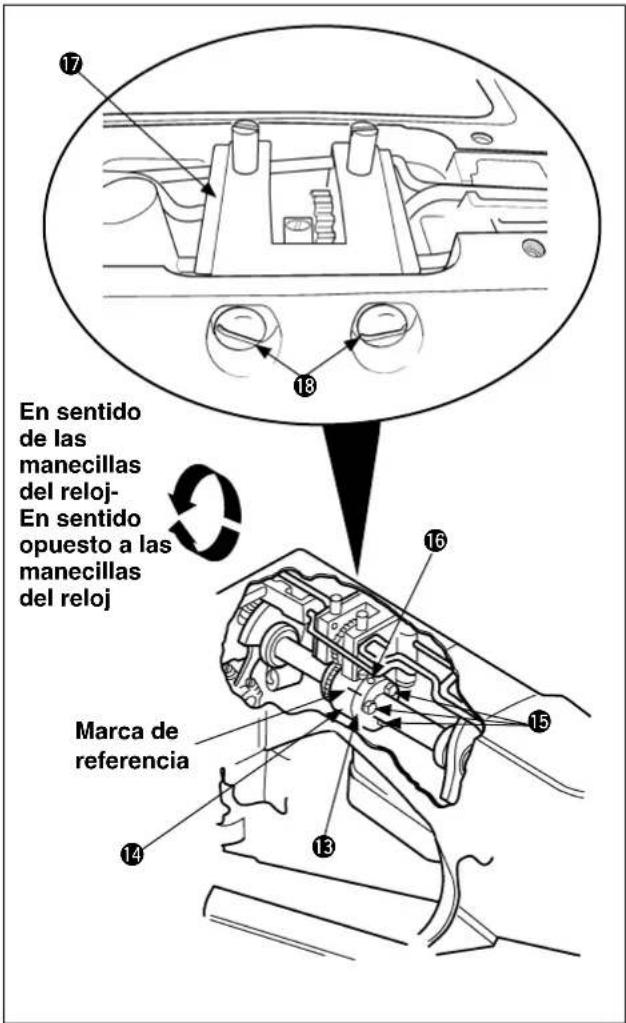
(2) Adjustment of the needle bar height
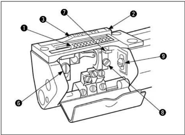
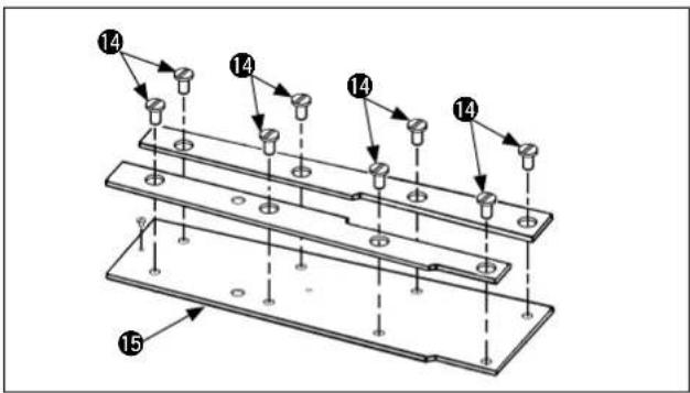
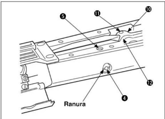
Coincidencia

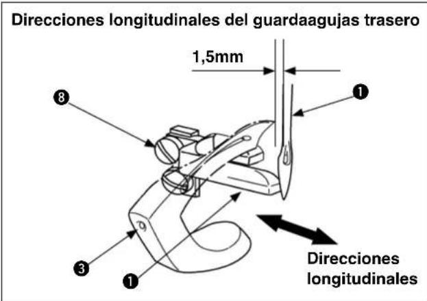
Subsequently, tighten another setscrew 5.
natural_image
Technical line drawing of a mechanical assembly with no visible text or symbolsV. PROBLEMAS Y MEDIDAS CORRECTIVAS
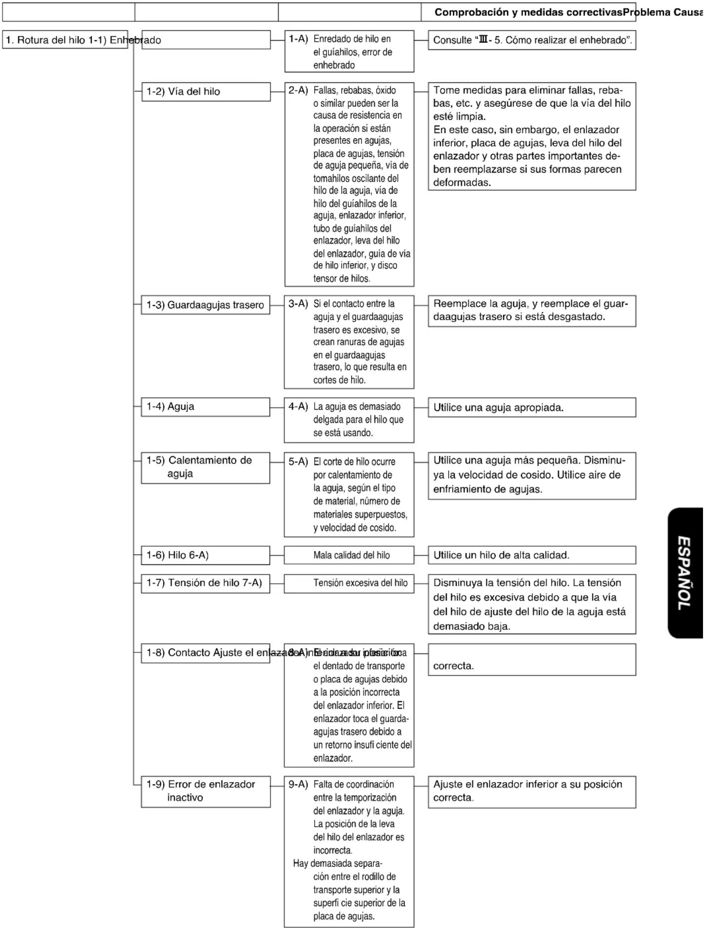
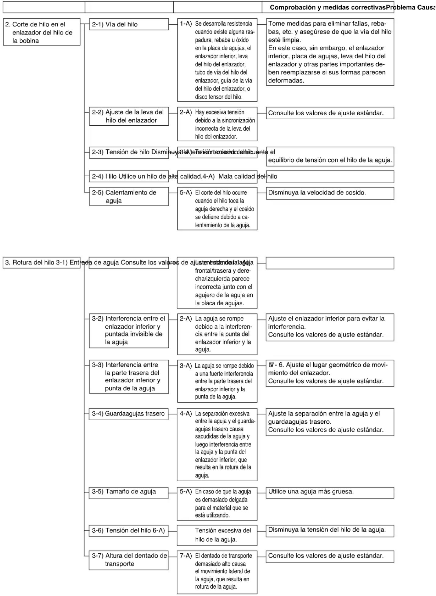
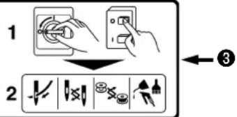
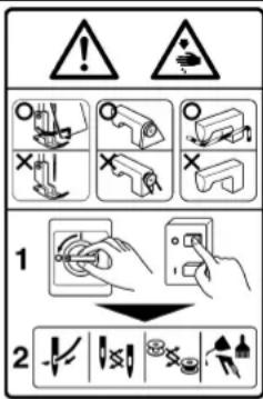


natural_image
Line drawing of hands holding a handheld electronic device with no visible text or symbolsnatural_image
Technical line drawing of a mechanical assembly with hands operating a tool (no text or symbols present)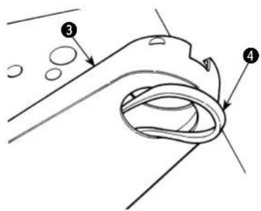
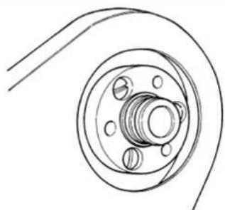
natural_image
Technical line drawing of a mechanical component with concentric rings and mounting holes (no text or symbols)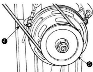
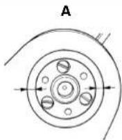

① Frizione asm.
natural_image
Technical line drawing of a mechanical assembly with gears and levers (no text or symbols)natural_image
Technical line drawing of a mechanical assembly with no visible text or symbols

natural_image
Technical line drawing of a mechanical assembly with spring and mounting bracket (no text or symbols)
natural_image
Line drawing of a hand inserting a component into a mechanical assembly (no text or symbols)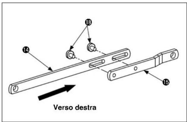
natural_image
Mechanical assembly diagram showing a gear and shaft assembly (no text or labels)natural_image
Technical line drawing of a mechanical assembly with springs and gears (no text or symbols)natural_image
Technical line drawing of a mechanical assembly with no visible text or symbolsnatural_image
Technical line drawing of a mechanical clamp or spring assembly (no text or symbols)natural_image
Technical line drawing of a mechanical assembly with springs and a central hub (no text or symbols)natural_image
Mechanical assembly diagram showing a rotating component with a directional arrow indicating motion (no text or symbols present)natural_image
Technical line drawing of a mechanical device with no visible text or symbols
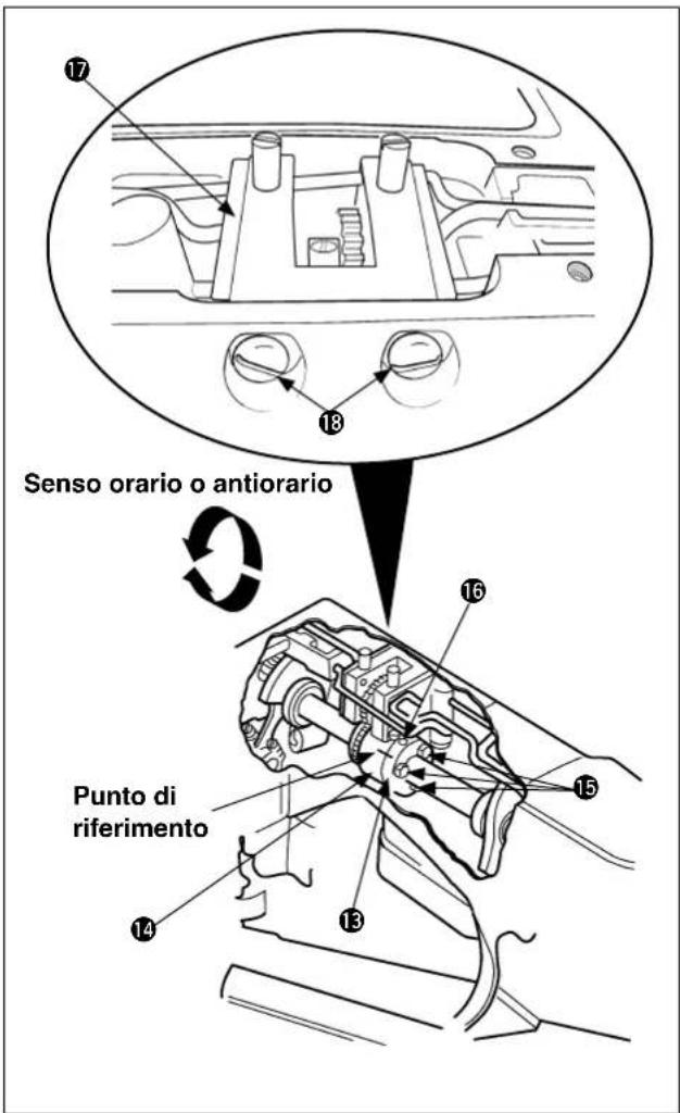

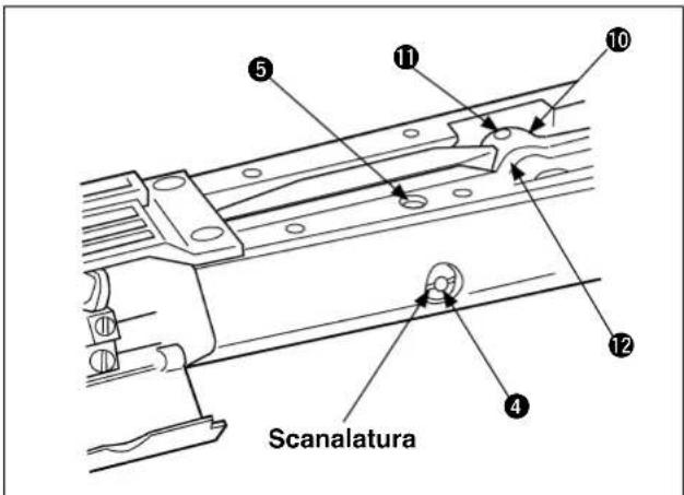
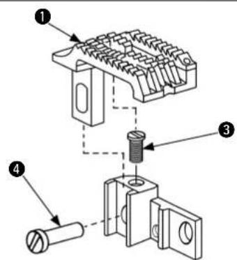

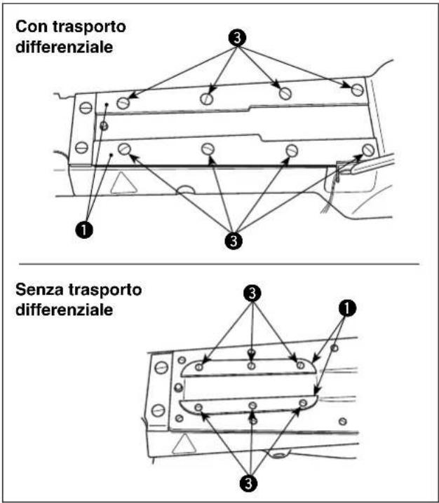
natural_image
Technical line drawing of a mechanical assembly with no visible text or symbolsnatural_image
Line drawing of hands holding a handheld electronic device with no visible text or symbols

natural_image
Technical line drawing of a mechanical assembly with hands operating a tool (no text or symbols)首先,说明一下开箱后机头的取出方法。
natural_image
Technical line drawing of a mechanical component with concentric rings and mounting holes (no text or symbols)5. 切线刀的安装方法
① 离合器组件
② 离合器连接曲柄
③ 离合器连接杆
4 针杆&辊罩
⑤ 压力调节螺母
6 压力调节弹簧板组件
⑦ 油循环确认窗(后)
8 线张力器旋钮
9 线张力导线器
10 油循环确认窗(前)
11 弯针按钮
12 前顶盖
13 后顶盖
14 线杆护罩
15 机线调节线道
16 辊端护罩
17 弯针导管
18 差动调节杆
19 加油栓兼用缝迹长度调节窗螺丝
20 机油标尺(前)
21 机油排油螺丝(前)
22 气缸侧罩
23 刻度板
24 传送摆动杆偏心销
25 弯针护罩
26 针板
27 三卷折叠器
28 压脚
29 护针器
30 针杆
31 齿轮护罩(前)
32 尺寸护罩(后)
33 上传送辊框架
34 上送辊
35 针座
36 左右导向板
37 辊杆导向板
38 辊压力调节弹簧
39 辊压力调节螺丝
40 机线杆导线器
④ 摆动挑线杆导线器
42 机线摆动挑线杆
43 机线座调节板
44 针线压板
2. 关于加油
注意

natural_image
Technical line drawing of a mechanical assembly with gears and levers (no text or symbols)natural_image
Technical line drawing of a mechanical assembly with no visible text or symbols弯针倾倒的状态弯针倾倒前的状态


natural_image
Technical line drawing of a mechanical assembly with no visible text or symbols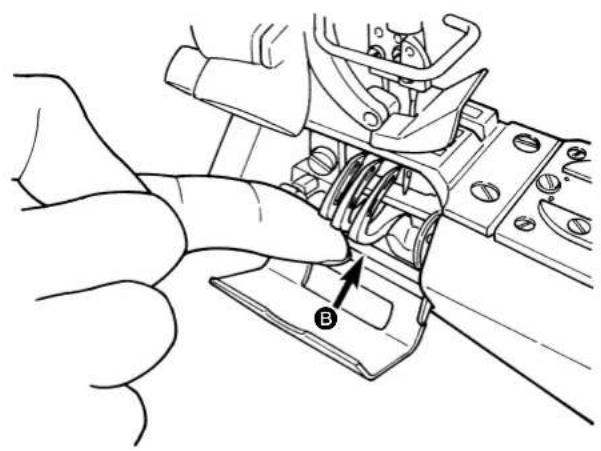
natural_image
Technical line drawing of a mechanical assembly with a hand adjusting a component (no text or symbols visible)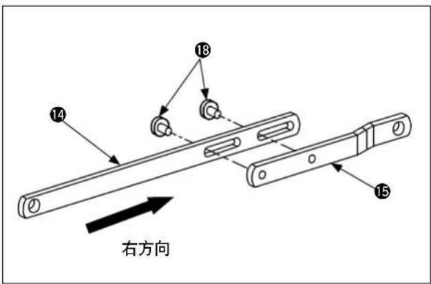
无差动
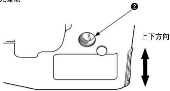
(1) 上传送辊拉出量
natural_image
Technical line drawing of a mechanical assembly with springs and gears (no text or symbols)2)用扳手卸下固定离合器联结杆的螺母。

natural_image
Technical line drawing of a mechanical assembly with no visible text or symbolsnatural_image
Technical line drawing of a mechanical clamp or bracket assembly (no text or symbols)natural_image
Technical line drawing of a mechanical assembly with springs and a central hub (no text or symbols)natural_image
Mechanical assembly diagram showing a rotating component with a directional arrow indicating motion (no text or symbols present)natural_image
Technical line drawing of a mechanical device with no visible text or symbols机头后方
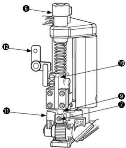
机头右侧面
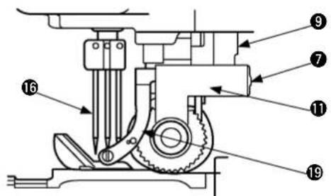
压力调节弹簧板组件
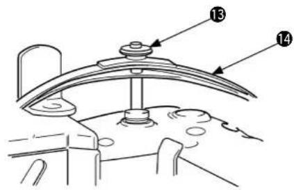
机头左侧面
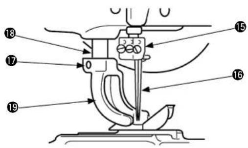
标尺组件部分(带差动机构)

标尺组件部分(无差动机构)
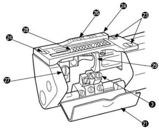

前弯针

① 返回量的调整方法是用标尺 ⑦ 和直

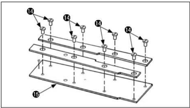

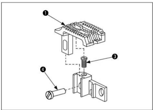

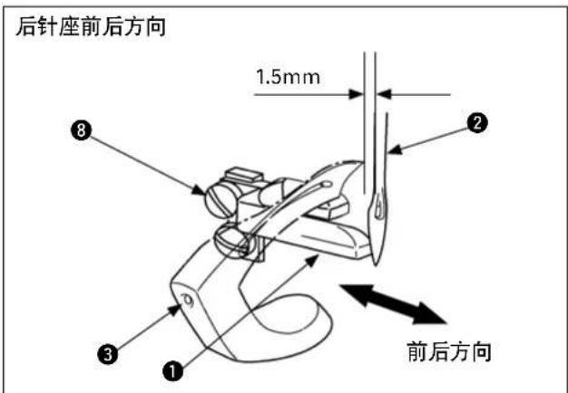
(2) 张力盘浮起的调整方法
(2) 折叠器安装位置的调整
natural_image
Technical line drawing of a mechanical assembly with no visible text or symbolsSEWING MACHINERY BUSINESS UNIT
2-11-1, TSURUMAKI, TAMA-SHI,
Copyright © 2010-2013 JUKI CORPORATION
• All rights reserved throughout the world.
Please do not hesitate to contact our distributors or agents in your area for further information when necessary.
* The description covered in this instruction manual is subject to change for improvement of the commodity without notice.