HGO 700 - Vacuum Cleaner HOOVER - Free user manual and instructions
Find the device manual for free HGO 700 HOOVER in PDF.

User questions about HGO 700 HOOVER
0 question about this device. Answer the ones you know or ask your own.
Ask a new question about this device
Download the instructions for your Vacuum Cleaner in PDF format for free! Find your manual HGO 700 - HOOVER and take your electronic device back in hand. On this page are published all the documents necessary for the use of your device. HGO 700 by HOOVER.
USER MANUAL HGO 700 HOOVER
MANUEL D'UTILISATION (FR)......12
MANUAL DE INSTRUÇÕES (PT) ..... 52
MANUAL DE USUARIO (ES) 62
BRUGERVEJLEDNING (DK) 72
BRUKERMANUAL (NO)......82
INSTRUKTIONSMANUAL (SE)....92
KÄYTTÖOHJE (FI) 102
natural_image
Line drawing of a mechanical device with no visible text, numbers, or symbolsINSTRUCTIONS FOR SAFE USE
This appliance should only be used for domestic cleaning, as described in this user guide. Please ensure that this guide is fully understood before operating the appliance.
Always switch off and remove the charger from the socket before cleaning the appliance or any maintenance task.
This appliance can be used by children aged from 8 years and above and persons with reduced physical, sensory or mental capabilities or lack of experience and knowledge if they have been given supervision or instruction concerning use of the appliance in a safe way and understand the hazards involved. Children shall not play with the appliance. Cleaning and user maintenance shall not be made by children without supervision.
If the power cord is damaged stop using the appliance immediately. To avoid a safety hazard, an authorised Hoover service engineer must replace the power cord.
If the area to be cleaned contains a balcony or stairs, a physical barrier should be used to prevent access to the balcony or stairs and ensure safe operation. Small children and pets must be supervised while the Robot is cleaning.
Always store the appliance indoors. Do not use outdoors or expose the appliance to the elements, humidity or heating sources (oven, fireplace, wet floor).
Do not expose the Robot or accessories to excessive heat / cold (keep between 0-30°C).
Do not drop the Robot or use any accessory if it has been dropped, damaged, left outdoors or dropped in water.
Never unplug or pull the mains power adaptor by the power cord.
Do not use to clean stairs.
Battery Charging
Use only the original charger supplied with the appliance.
Check that your supply voltage is the same as that stated on the charger.
Never charge the batteries in temperatures above 30^ C or below 0^ C.
Plug the charger delivered with this appliance into a suitable socket.
Leaks from battery cells can occur under extreme usage or temperature conditions. If the liquid gets on skin, wash quickly with water. If the liquid gets into the eyes, flush them immediately with clean water for a minimum of 10 minutes. Seek medical attention.
It is normal for the charger to become warm to the touch when charging.
Use only attachments, consumables or spares recommended or supplied by Hoover.
Do not pick up hard or sharp objects, matches, hot ashes, cigarette ends or other similar items.
Do not spray with or pick up flammable liquids, cleaning fluids, aerosols or their vapours.
Do not continue to use your appliance or charger if it appears faulty.
Hoover service: To ensure the continued safe and efficient operation of this appliance we recommend that any servicing or repairs are only carried out by an authorised Hoover service engineer.
Do not use the appliance to clean animals or people.
Do not replace the Robot batteries with non-rechargeable batteries.
If the Robot will not be used for a long time (several weeks), unplug the mains power adaptor.
End of life battery removal
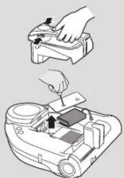
If the appliance is to be disposed of the batteries must first be removed. The appliance must be disconnected from the supply mains when removing the battery. Dispose of the batteries safely. Run the appliance until it stops because the batteries are fully discharged. Used batteries should be taken to a recycling station and not disposed of with household waste. To remove the batteries, please contact the Hoover Customer Centre or proceed according to the following instructions. Unplug the charger and switch off the Robot. Turn the Robot over and place on a level surface. Remove the screws and battery compartment cover. Remove the battery pack. [Fig. 6]
NOTE: Should you experience any difficulty in dismantling the unit or for more detailed information on treatment, recovery and recycling of this appliance, please contact your local city office or your household waste disposal service.
IMPORTANT NOTES BEFORE USE
Please read the following information carefully before using your Robot or its accessories.
Do not disassemble the Robot and do not attempt to repair it yourself. If a fault occurs, please contact the Hoover after Sales Service for professional advice.
Stairs: The Robot uses sensors to avoid falling down steps, stairs or over an edge. In some situations the sensors can become confused.
The Robot cannot detect steps that are less than 8cm in height. Steps less than 8cm may cause the Robot to fall down. If available, use the Virtual Barrier to protect your Robot from falling.
Highly reflective or very dark surfaces used on some steps or stairs, such as glass or polished ceramics may cause the Robot to fall down. If available use the Virtual Barrier or place a carpet on the lower step to protect your Robot from falling.
Using your Robot on mezzanines, landings or raised areas without borders should be avoided. Prevent your Robot entering these areas.
Battery Use: Your Robot is powered by rechargeable, high capacity lithium ion batteries. These rechargeable batteries are guaranteed for a period of 6 months if they are maintained and operated according to this User Manual.
In the event of a significant drop in the Robot's performance, replacement batteries can be obtained from your Hoover retailer.
Only use Hoover approved replacement parts for your Robot. Use of parts that are not approved by Hoover are dangerous and will invalidate your warranty.
Only use the supplied charging station and mains power adaptor to recharge your Robot. Use of the incorrect charging station or mains power adaptor is dangerous and will invalidate your warranty.
| Frequency bands 433.92Mhz | |
| Maximum RF power transmitted in the frequency band 6dBm | |
The Environment
The symbol on this appliance indicates that this appliance may not be treated as household waste. Instead it must be handed over to the applicable collection point for the recycling of electrical and electronic equipment. Disposal must be carried out in accordance with local environmental regulations for waste disposal. For more detailed information about treatment, recovery and recycling of this appliance, please contact your local city office, your household and waste disposal service or the shop where you purchased the appliance.

This appliance complies with the European Directives 2014/53/EU and 2011/65/EU. To receive a copy of the declaration of conformity, please contact the manufacturer through the website: www.candy-group.com
CANDY HOOVER GROUP Srl Via Privata Eden Fumagalli, 20861 Brugherio (MB) Italy
CONTENTS OF THE BOX
natural_image
Technical line drawing of a mechanical component with no visible text or symbols
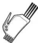
natural_image
Line drawing of a printer with a flat base and clasp (no text or symbols)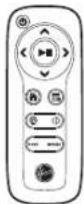
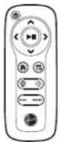
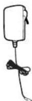
Robot Cleaner Charger Base Remote Control
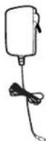
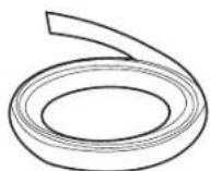
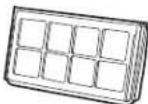
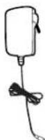
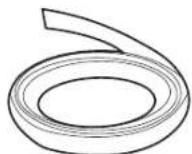
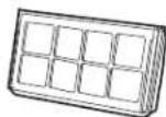
Mains Power Adaptor Virtual Wall Magnetic Strip* Filter pack
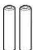
X2 AAA Batteries Cleaning Brush
X1 Additional Filter*
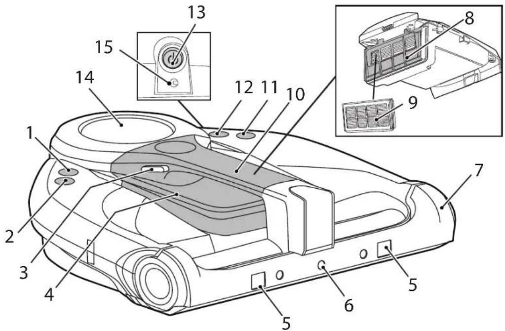
GETTING TO KNOW YOUR CLEANER
ROBOT TOP VIEW
text_image
Technical diagram of a vacuum cleaner with numbered parts and labeled components| 1 Start/Pause Button |
| 2 Home Charging Station Button |
| 3 Dust Container Release Buttons |
| 4 Dust Container |
| 5 Obstacle Sensors |
| 6 LED Lights |
| 7 Frontal Bumper |
| 8 Filter Frame Holder |
| 9 Filter |
| 10 Dust Bin Handle / Robot Carry Handle |
| 11 Wifi Button |
| 12 Spot Mode Button |
| 13 On/Off Power Button |
| 14 Display |
| 15 Charging Connector |
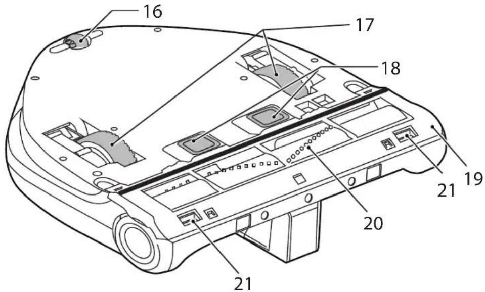
ROBOT BOTTOM VIEW
text_image
16 17 18 21 19 20 21| 16 Rear Wheel |
| 17 Drive Wheels |
| 18 Charging Contacts |
| 19 Agitator Cover |
| 20 Agitator |
| 21 Anti-Fall Sensors |
GETTING TO KNOW YOUR ROBOT CLEANER
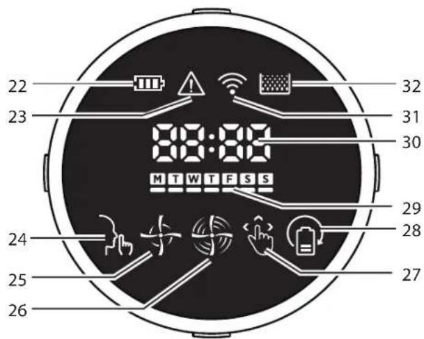
ROBOT DISPLAY PANEL
text_image
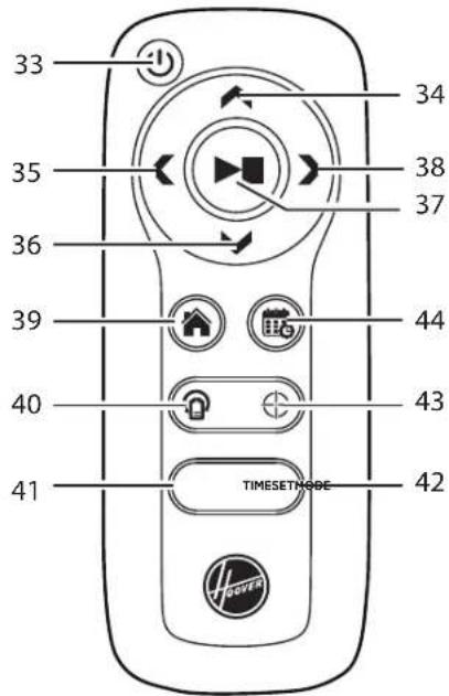
22 23 24 25 26 32 31 30 MTWTFSS 29 28 27ROBOT REMOTE CONTROL
text_image
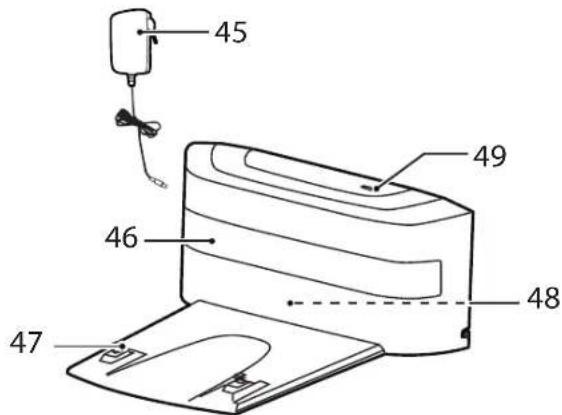
33 34 35 38 37 36 39 44 40 43 41 TIMESETMOSE 42ROBOT CHARGER BASE
text_image
45 49 46 48 47* Certain Models Only
| 22 Battery Level Indicator |
| 23 Attention Status / Errors indicator |
| 24 Silent Mode |
| 25 Standard/Auto Mode |
| 26 Turbo Mode |
| 27 Manual Mode |
| 28 Full & Go Mode |
| 29 Daily Schedule |
| 30 Time Display / Error Code |
| 31 WiFi Status |
| 32 Dust Bin Full Indicator |
| 33 Power On/Off Button |
| 34 Button Forward |
| 35 Button Left |
| 36 Button Backward |
| 37 Start/Pause Button |
| 38 Button Right |
| 39 Home Charging Station Button |
| 40 Full & Go Mode |
| 41 Mode Selection Button |
| 42 Time Setting |
| 43 Spot Mode |
| 44 Scheduling Button |
| 45 Mains Power Adaptor |
| 46 Infrared Signal Window |
| 47 Charging Contacts |
| 48 Power Supply Connector |
| 49 Power Indicator |
GB
natural_image
Line drawing of a robotic vacuum cleaner with attached power outlet, no text or symbols presentFig. 1

text_image
1m 2m 1mFig. 2

Fig. 3

text_image
Diagram showing a remote control interface with hand placement, power plug, and device insertion stepFig. 4


natural_image
Line drawing of a robotic arm with attached cable and housing (no text or symbols)Fig. 5

natural_image
Diagram showing a hand operating a device with a close-up of its internal components (no text or symbols visible)PREPARE YOUR ROBOT CLEANER
PACKAGING
Do not dispose of your Robot packaging. It may be required for the validity of your guarantee in the future.
When unpacking your Robot and its accessories, take care to keep plastic bags away from babies, young children and animals to avoid the risk of suffocation.
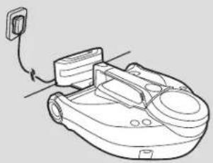
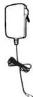
Before first use, charge your appliance for 8 hours. [Fig. 1]
Do not expose the Robot's mains power adaptor to temperatures below 0^ or above 30^ as this may damage the battery.
The mains power adaptor must only be connected to a standard mains power outlet.
BATTERY
For optimum battery performance it is recommended that you keep your robot batteries fully charged. When the robot is not in use it should be left connected to the mains power adaptor. The robot has an intelligent charging system. This prevents the batteries from becoming overcharged.
To avoid accidents, make sure that every person in the room is aware of the presence of the Robot.
Charging station Setup
Before use, remove obstacles that may get in the path of the Robot. Pay attention to:
- Objects that can be easily knocked over.
- Edges of carpets or rugs that it may get caught on.
• Floor length curtains and tablecloths.
- Heat sources or flammable items.
• Power cords and cables.
- Fragile objects.
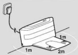
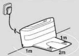
Plug in the mains power adaptor and connect to the charging station. [Fig. 2]
-
Make sure the power cord is not caught underneath the charging station.
-
Place the charging station on a non-reflective level floor, preferably against a wall. If the floor surface is too reflective, it will interfere with the Robot navigation system and it may have difficulty locating the charging station.
-
There should not be any objects in the area around the charging station for 2 meters in front and 1 meter to each side. [Fig. 2]
-
Make sure the power cord is not tangled or stretched. If there is an excess, use the power cord storage on the rear of the charging Station.
-
Check that the dust container is inside on Robot.
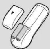
Remote Control Setup
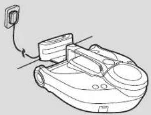
Open the battery compartment on the back of the remote control. Insert two AAA / LR03 batteries into the battery compartment. [Fig. 3] Observe the correct polarity (+/-).
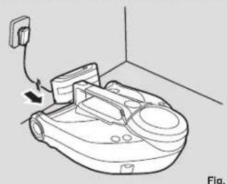
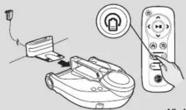
Charging the battery
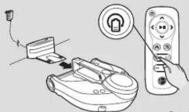
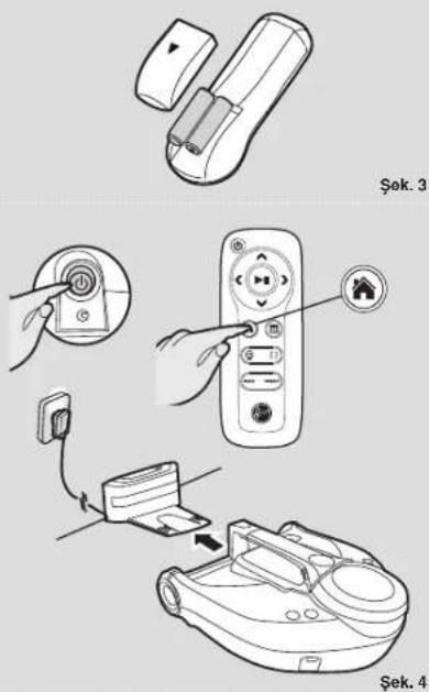
Switch on the vacuum robot with the on/off button on the side (1). [Fig. 4] Set it down in front of the charging station.
Guide your Robot into the charging station to begin. During normal use, it will take approximately 4/5 hours to complete a full recharge.
Manual charging
There are several methods to charge your robot.
A. By pressing the Home charging button on your remote control.
B. By pressing the Home charging button on your robot.
C. By connecting the mains power adaptor directly to the robot.
D. By manually placing the robot on the charging station.
E. Following the instruction in the WiFi Application*.
Automatic charging
When the robot battery capacity is LOW it will stop cleaning and search for the charging station. Once docked with the charging station, the charging indicator on charging station will flash.
The robot may fail to reach the charging station if there are too many obstacles in between it and the charging station. For best results ensure that the charging station is in a wide open space.
NOTE: Make sure that the charging contacts of the robot vacuum cleaner and charging base are not dirty. Clean the contacts if necessary.
It is normal for the charging base and vacuum cleaner to become warm during charging.
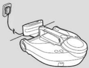
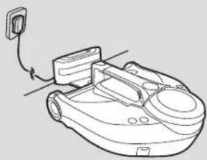
When the battery is charging, Power Indicator LED on the charger base and the Battery Level Indicator on product's display flash. If the battery is fully charged, they are on permanently. [Fig. 5]
Battery
Over time the capacity of your robot battery will diminish and it will need to be replaced. A replacement battery can be purchased from an approved Hoover retailer. Only use genuine Hoover spares and accessories.
Removal and replacement
Ensure the robot is switched OFF.
Locate the battery compartment under the robot's dust container and remove the two screws.
Remove the battery from the compartment and disconnect the connector.
Refit a new battery and reconnect the connector. Pay attention to correct alignment of the connector.
Refit the battery cover and the two screws. [Fig. 6]
Virtual Wall Magnetic Strip\* Setup
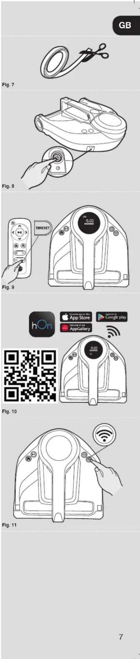
The robot comes with Virtual wall Magnetic Strip*. These strips create a physical threshold that prevents your robot crossing. You can use scissors to adjust the size of the stripe for greater customization. [Fig. 7]
Place the magnetic strip in a doorway to prevent it entering or leaving a particular room.
USING YOUR ROBOT CLEANER
Power On
-
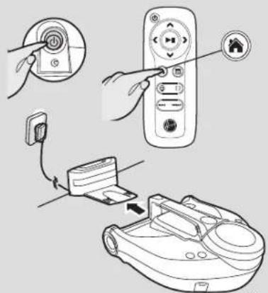
Press the ON/OFF power button on the side of the robot. [Fig. 8]
-
The product display will illuminate.
In standby mode, the display is off. To activate the robot press the the start/ pause button on the remote control or on the product.
Set time
- Press the Timeset button on the remote control, a flashing line will appear below the day icon. [Fig. 9]
- Use the right and left arrow on the remote control until the line appears below the correct day. Press the Start/Pause button to confirm.
- The hour display will flash. Press the up and down arrow on the remote control until the correct hour is displayed. Press the Start/Pause button to confirm.
- The minute display will flash. Press the up and down arrow on the remote control until the correct minute is displayed. Press the Start/Pause button to confirm.
- Day and time are now set.
APP DOWNLOAD AND CONNECTION VIA THE WIFI\*
In order to access all the Robot's functions from anywhere, it is suggested to download the hOn App. You will be able to control the Robot in the most efficient way.
App advantages:
- Control your robot in an easy and intuitive way
- Activate the cleaning process from anywhere
- Carry out settings and daily scheduling
- Choose between its different and customized cleaning programs
Instructions:
- Download the hOn application from the App Store or Google Play. [Fig. 10]
- Open the APP, create an account with your e-mail and a password.
- Confirm login.
- Ensure your mobile device is connected to WiFi.
- Log into the hOn APP.
- Press the ON/OFF power button on the side of the robot. [Fig. 8]
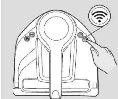
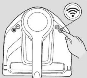
- Switch the WiFi ON by pressing the WiFi button on main product. [Fig. 11]
- Press and hold the WiFi button on main product for 5 seconds, there will an audible beep and the WiFi button will start flashing to indicate it is waiting for a connection. [Fig. 11]
- Follow the in APP instructions to connect your mobile device to your product.
- When successfully paired, the WiFi button on the product will remain illuminated.
- To reset the WiFi, press & hold the WiFi button om main product for 5 Secs.
WARNING
• The WiFi name cannot exceed 32 characters.
- If the network configuration fails to connect, follow the below steps:
a) Make sure to have inserted correct router WIFI password.
b) Make sure to set your WiFi network to 2.4GHz.
c) Make sure the robot is not far away from the router.
* Certain Models Only
text_image
GB Fig. 7 Fig. 8 34 5:00 TIMESET Fig. 9 hOn Downloaded on the App Store Google play AppGallery 5:00 5:00 6:00 7 Fig. 10 Fig. 11GB
text_image
Diagram illustrating a device operation with labeled components including a play button, remote control, and audio output.Fig. 12

text_image
Diagram illustrating a device operation with labeled components and directional arrows indicating motion or feedback.Fig. 13
natural_image
Diagram showing a device being inserted into a remote control unit, with no visible text or symbols.Fig. 14

natural_image
Technical line drawing of a mechanical clamp or bracket assembly (no text or symbols)Fig. 15

text_image
Diagram showing a device with a mode label and three abstract circular patterns below, likely illustrating a control or layout concept.Fig. 16
Cleaning Programs
The robot offers different cleaning programs which adapt to different cleaning needs:
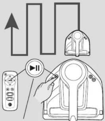
AUTO CLEANING MODE
Press the Start/Pause Button on the remote control, on the product or use Wifi application, the robot will automatically start operating.
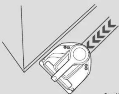
The robot vacuums in an organized and efficient way, it features gyroscopic navigation to provide precise directional signals. [Fig. 12]
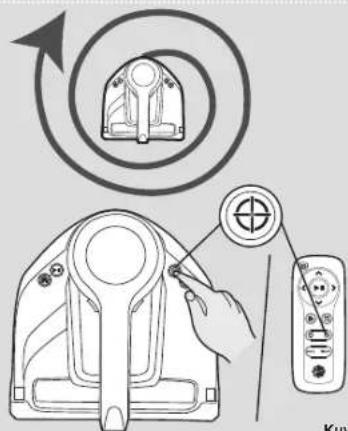
SPOT CLEANING MODE
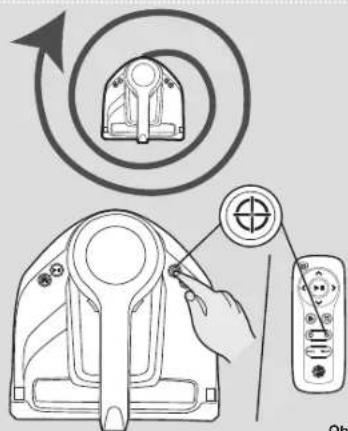
Press the Spot Button on the remote control, on the product or use the Wifi application*, the robot will automatically start operating. It cleans intensively a confined area following a circular path turning automatically the power on TURBO power level. [Fig. 13]
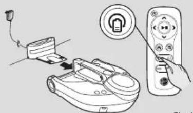
FULL & GO CLEANING MODE
Press the FULL & GO button on the remote control or the Wifi application* to make robot return to the base. On the display the FULL & GO indicator will be illuminated. After being fully charged, the robot will automatically start a new cleaning cycle and the FULL & GO option will be reset. [Fig. 14] If you want to delete this mode, press again FULL & GO on the remote control.
MANUAL CLEANING MODE
The robot can be controlled manually at any time during a cleaning program. The navigation arrow buttons on the remote control / WiFi application* will move the robot in the desired direction with the suction activated.
EDGE CLEANING MODE
Press Edge Cleaning mode in the Wifi application*. It will automatically start cleaning along walls, around furniture etc. [Fig. 15]
HOME MODE:
You can command your robot return to the Home charging station for charging by:
-
Press the Home button on the robot
-
Press the Home button on the remote control
-
Following the instruction in the WiFi Application*.
NOTE: The Robot will return to its home charging station when the cleaning session is started from the charging base.
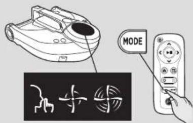
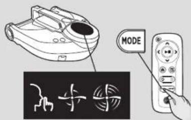
Setting Power Level
Press MODE button on the remote control or use the Wifi application* to select the desired power level. Choose between:
- Silent Power
- Standard Power
- Turbo Power
Icons on product display will illuminate according to your choice. [Fig. 16]
Setting up the Cleaning Schedule with remote control
The robot can be programmed to automatically clean each day or on specific days as desired. To set up a cleaning schedule over one week complete the following:
-
Press the scheduling function button on the remote control. A flashing box will appear around M (Monday).
-
Use the right and left arrow buttons to select the desired day and then press the Start/Pause button to confirm that day. You can also choose multiple days(up to 7days) and different hours for each day.
-
Once the day of the week has been selected, you can decide the hour of the cleaning schedule: use the up arrow, the hour will start flashing on the display, use the up and down arrow to select the desired hour. Press the Start/Pause confirmation button.
-
The minute display will flash, use the up and down arrow keys to select the desired minute. Press the Start/Pause confirmation button.
-
Press the scheduling function button to save the time and week settings. You can easily see it, thanks to the illuminated dash under scheduled day/days.
If you want to reset the scheduling settings, press the scheduling function button, use the right and left arrow buttons and press the Start/Pause button to delete the schedule on the specific day/days.
With WiFi Application\*
Following the instruction in the WiFi Application*.
MAINTAINING YOUR ROBOT CLEANER
Before performing any maintenance task, ensure the robot is switched off.
- Turn the robot off and remove it from the charging station.
- Use a damp cloth to clean all surfaces. DO NOT allow water into any part of the product whilst cleaning.
- Dry with a soft cloth.
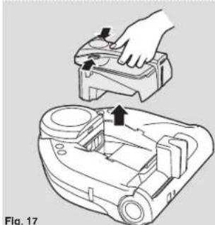
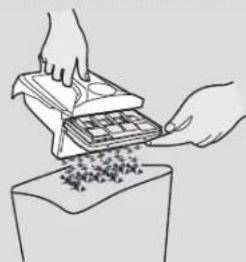
EMPTYING THE DUST CONTAINER
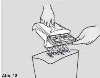
After vacuuming, remove the dust container.
- Press the dust container release buttons and pull it out. [Fig. 17]
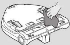
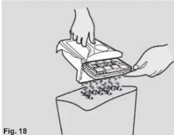
- Hold the dust container over a dust bin and empty it. [Fig. 18]
- Use the cleaning brush when necessary to remove any excess dust from the internal surface of the dust container or filter surface.
- Refit the dust container to the robot.
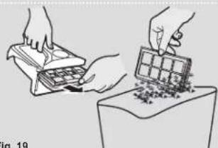
CLEANING THE FILTERS
The robot is fitted with a pre-motor filter. To maintain optimum cleaning performance, regularly clean and wash the filter cover and the pre-motor filter. It should be cleaned after the dust container has been emptied 5 times. Failure to clean your filter may result in air blockage overheating and product failure. This may invalidate your guarantee.
- Turn the robot off and remove from the charging station.
- Press the dust container release button and remove the dust container from the Robot. [Fig. 17]
- Remove the filter and clean. [Fig. 19] The assembly is done in reverse order.
Make sure, that the filter insert is correctly assembled.
IMPORTANT: Regularly check and maintain the filter by following the filter maintenance instructions. This will maintain your Robot's performance.
IMPORTANT: Always ensure the filter is fully dry before use.
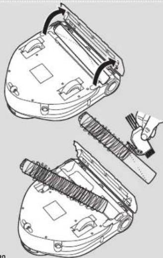
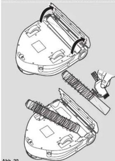
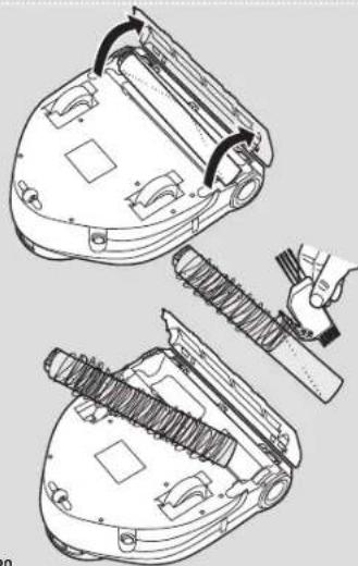
CLEANING THE AGITATOR
Regularly clean the agitator to maintain maximum cleaning performance.
- Turn the Robot off.
- Turn the Robot over.
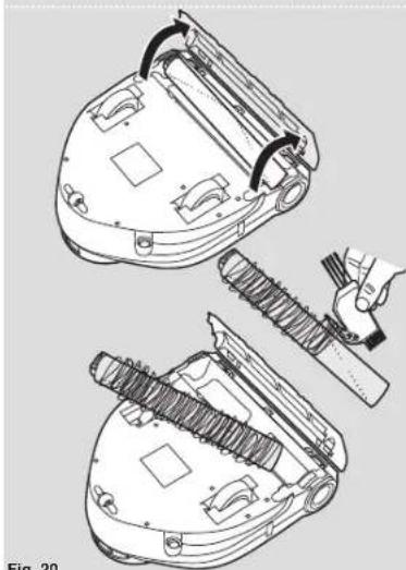
- Press the clips on the soleplate and remove the agitator cover. [Fig. 20]
- Remove the agitator and clean away any hair or fibers Etc using scissors or with the cleaning brush provided. [Fig. 20]
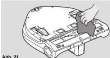
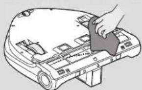
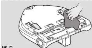
CLEANING THE DRIVE WHEELS
- Switch the Robot off and turn it over.
- Remove any dirt or hair trapped in the wheels.
- Clean the wheels with a dry cloth. [Fig. 21]
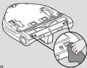
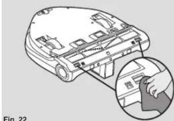
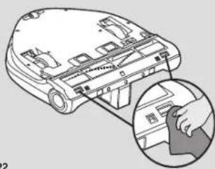
CLEANING ANTI FALL SENSORS
To maintain the safe operation of your robot it is important to keep the Anti fall sensors clean. There are 2 sensors located on the underside of the robot. Turn the robot upside down and clean them with a soft brush to remove any accumulation of dust, dirt or debris. [Fig. 22]
IMPORTANT NOTICE
Only use approved replacement parts for your Robot.
Using parts not validated by Hoover are dangerous and will invalidate your guarantee.
If the Robot will not be used for several months, please remove the batteries and store in cool a dry location.
IMPORTANT: Always make sure your device is switched off before maintenance.
natural_image
Diagram of a hand operating a robotic device with a handle, showing mechanical components and motion direction (no text or symbols)Fig. 17

natural_image
Illustration of hands exchanging a tray with small objects on a base (no text or symbols)Fig. 18

natural_image
Illustration of hands counting and stacking a small object on a surface (no text or symbols)Fig. 19
natural_image
Technical line drawing of a robotic vacuum cleaner with attached screw and handle assembly (no text or symbols)Fig. 20
natural_image
Line drawing of a hand cleaning a car's seat panel with a cloth (no text or symbols)Fig. 21
natural_image
Diagram of a computer monitor with an inset showing a hand inserting a component (no text or symbols present)Fig. 22
text_image
E:0 M T W F S S Figure 23Fig. 23
TROUBLESHOOTING
The following is a list of commonly encountered problems and solutions. If any of these problems persist contact your local Hoover representative.
| The Robot does not work | Check that the Robot is switched on.Check that the dust container and filter are clean.Check that the dust container is fully inserted in Robot body.Check if the Robot needs to be charged. |
| Cleaning power is weak | Turn power off and empty dust container.Check and clean the filter.Check and clean the agitator.Check and clean the sensors.Check and clean the drive wheels. |
| The Robot is very noisy while cleaning | Clean the dust container and filter.Check the agitator and drive wheels for dirt and debris. |
| The Robot does not automatically charge | Make sure there are no barriers between the Robot and the charger station. |
| Robot is trapped | The Robot will attempt to free itself but in some cases assist the Robot manually. |
| The remote control doesn't work | Check the batteriesMake sure the Remote Control is close to the RobotThe Robot and the Remote Control are not paired. For pairing, please follow the below instructions:- Press simultaneously the buttons PLAY/PAUSE and HOME on the Robot main body and the red ON/OFF button on the Remote Control. |
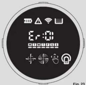
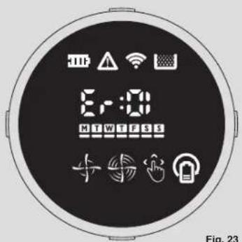
ERROR CODES
The following codes may appear during use or on start up. [Fig. 23]
| Failure Code | Error Description Error | Solution |
| Er01 Agitator obstructed Remove obstruction and ensure agitator is free to rotate | ||
| Er02 Left drive wheel is obstructed | Remove obstruction and ensure the drive wheel is free to rotate | |
| Er03 Right drive wheel is obstructed | Remove obstruction and ensure the drive wheel is free to rotate. | |
| Er04 Dust container or pre motor filter missing | Ensure that both dust container and pre motor filter are fitted inside the robot correctly | |
| Er05 Pre motor filter is blocked | Remove and clean the dust container and pre motor filter | |
| Er06 Bumper is stuck Check around the bumper and remove any obstructions preventing its function | ||
| Er07 Cliff edge sensors require cleaning | Remove any accumulated dust or debris from the cliff edge sensors with a soft brush or cloth | |
| Er08 Drive wheel not touching the floor | Ensure the robot is placed on a flat level surface and both drive wheels are touching the ground | |
| Er09 Robot is stuck Reposition the robot in an area where it can navigate freely | ||
| Er10 Suction motor malfunction | Inspect all airpaths for any blockage or obstruction | |
| Er11 Dust container full Remove and empty the dust container | ||
| Er12 Agitator inspection Ensure to remove any debris or hair trapped around the agitator | ||
| Er13 Agitator replacement Agitator is worn, please replace with a new one. | ||
ATTENTION: If any of these failures persist, contact your local Hoover representative. DO NOT try to disassemble the Robot by yourself.
IMPORTANT INFORMATION
Hoover Spares and Consumables
Always replace parts with genuine Hoover spares. These are available from your local Hoover dealer or direct from Hoover. When ordering parts always quote your model number.
Quality
Hoover's factories have been independently assessed for quality. Our products are made using a quality system which meets the requirements of ISO 9001.
Your Guarantee
The guarantee conditions for this appliance are as defined by our representative in the country in which it is sold. Details regarding these conditions can be obtained from the dealer from whom the appliance was purchased. The bill of sale or receipt must be produced when making any claim under the terms of this guarantee.
Subject to change without notice.
INSTRUCTIONS DE SÉCURITÉ D'UTILISATION
natural_image
Technical line drawing of a mechanical component with no visible text or symbols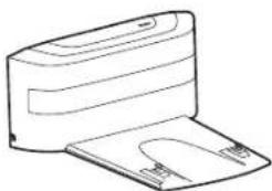
natural_image
Line drawing of a printer with a paper clip and base (no text or symbols)text_image
Technical diagram of a vacuum cleaner with numbered parts and labeled componentsnatural_image
Line drawing of a robotic vacuum cleaner with attached power outlet (no text or symbols)Fig. 1

text_image
1m 1m 2mFig. 2

Fig. 3

text_image
Diagram showing a remote control interface with buttons, power plug, and device connection stepsFig. 4


natural_image
Line drawing of a robotic arm with attached cable and housing (no text or symbols)Fig. 5

natural_image
Diagram showing a hand operating a device with a close-up view of the internal components (no text or symbols present)PRÉPARATION DE VOTRE ROBOT
EMBALLAGE
text_image
Diagram illustrating a device operation with labeled components including a play button, remote control, and audio output.Fig. 12

text_image
Diagram showing a hand holding a device with a circular indicator and plus symbol, alongside a circular diagram with an arrow indicating rotation or direction.Fig. 13

natural_image
Diagram showing a remote control with an open lock icon and a device being inserted (no text or symbols present)Fig. 14

natural_image
Technical line drawing of a mechanical clamp or bracket assembly (no text or symbols)Fig. 15

text_image
MODEFig. 16
text_image
E:0 M T W F S S Figure 23Fig. 23
DÉPANNAGE
natural_image
Line drawing of a mechanical device with no visible text or symbolsnatural_image
Line drawing of a printer with a flat base and clamped slots (no text or symbols)
text_image
Technical diagram of a vacuum cleaner with numbered parts and close-up insets for component identificationnatural_image
Line drawing of a robotic vacuum cleaner inside a room, showing mechanical components and a wall-mounted power outlet (no text or symbols)Abb. 1

text_image
1m 1m 2mAbb. 2

Abb. 3

text_image
Diagram showing a remote control device with labeled buttons and a close-up of its internal components.Abb. 4

natural_image
Line drawing of a robotic arm with attached cable and housing (no text or symbols)Abb. 5

natural_image
Illustration of a hand using a device to install a small electronic component (no text or symbols visible)Abb. 6
natural_image
Line drawing of a hand inserting a button into a small mechanical device (no text or symbols)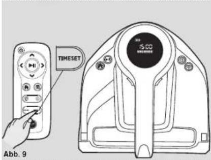
text_image
TIMESET 50 CO 5000000 Abb. 9
text_image
hOn Download on the App Store Google play Apache It On AppGalleryAbb. 10
text_image
Diagram showing a hand interacting with a device component, with a Wi-Fi signal icon and labeled buttons.Abb. 11
DE

text_image
Diagram illustrating a device operation with labeled components including a play button, remote control, and audio output.Abb. 12

text_image
Diagram showing a hand interacting with a device labeled 'Abk' and a circular diagram with an arrow indicating rotation or transformation.Abb. 13

natural_image
Diagram showing a device being inserted into a remote control with an open lock icon (no text or symbols present)Abb. 14

natural_image
Technical line drawing of a mechanical clamp or bracket assembly (no text or symbols)Abb. 15

text_image
MODEAbb. 16
Reinigungsprogramme
natural_image
Diagram of a hand operating a robotic device with a handle, showing mechanical components and motion arrows (no text or symbols)Abb. 17
natural_image
Illustration of hands exchanging a tray of small objects into a container (no text or symbols)
natural_image
Illustration of hands handling a tray and a grid of small objects on a table (no text or symbols)Abb. 19
natural_image
Technical line drawing of a robotic vacuum cleaner with attached screw and handle components (no text or symbols)Abb. 20
natural_image
Illustration of a hand using a tool to clean or store electronic components on a device (no text or symbols visible)Abb. 21

text_image
Abb. 22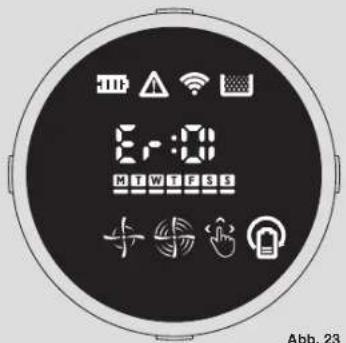
text_image
6:0 MTWFS Abb. 23FEHLERSUCHE
natural_image
Technical line drawing of a mechanical component with no visible text or symbols
natural_image
Line drawing of a printer with a clasp and paper holder (no text or symbols)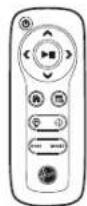
text_image
Technical diagram of a vacuum cleaner with numbered parts and labeled ports, including control panel and internal components.natural_image
Line drawing of a robotic vacuum cleaner with attached power outlet, no text or symbols presentFig. 1

text_image
1m 1m 2mFig. 2
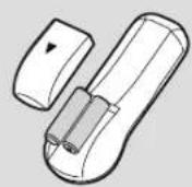
Fig. 3

text_image
Diagram showing a remote control interface with labeled buttons and a device being inserted into a device.Fig. 4


natural_image
Line drawing of a robotic arm with attached power outlet (no text or symbols)Fig. 5
natural_image
Diagram showing a hand operating a device with a close-up of its internal components (no text or symbols visible)PREPARAZIONE DEL VOSTRO ROBOT
IMBALLO
text_image
Fig. 7 Fig. 8 FIG. 9 hOn Downloaded on the App Store Google play appGallery 5:00 37IT

text_image
Diagram illustrating a device operation with labeled components including a play button, remote control, and audio output.Fig. 12

text_image
Diagram illustrating a device operation with labeled components and directional arrows indicating motion or feedback.Fig. 13

natural_image
Illustration of a remote control device with a lock icon and cable connector (no text or symbols)Fig. 14

natural_image
Technical line drawing of a mechanical clamp or bracket assembly (no text or symbols)Fig. 15

text_image
MODEFig. 16
text_image
8:00 M T W F S S Fig. 23Fig. 23
natural_image
Line drawing of a mechanical device with no visible text or symbols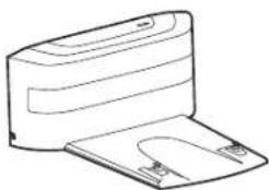
natural_image
Line drawing of a printer with a flat base and clamped cover (no text or symbols)Robotreiniger Laadbasis Afstandsbediening

text_image
Technical diagram of a vacuum cleaner with numbered parts and close-up insets for component identificationnatural_image
Line drawing of a robotic vacuum cleaner inside a room, showing mechanical components and wiring (no text or symbols)
text_image
1m 1m 2mAfb.1
Afb. 3

text_image
Diagram showing a remote control with a switch, power plug, and device with a home control icon, illustrating the process of switching from a power plug to a device.Afb. 4


natural_image
Line drawing of a robotic arm with attached sensor and cable (no text or symbols)Afb. 5

natural_image
Diagram showing a hand inserting a device into a device with an arrow indicating the component (no text or symbols present)Afb. 6
BEREID UW ROBOT VOOR
VERPAKKING
text_image
Diagram illustrating a device operation with labeled components including a play button, remote control, and audio output.Afb. 12

text_image
Diagram illustrating a device operation with labeled components and directional arrows indicating motion or feedback.Afb. 13
natural_image
Diagram showing a device being inserted into a remote control with an open lock icon (no text or symbols present)Afb. 14

natural_image
Technical line drawing of a mechanical clamp or bracket assembly (no text or symbols)Afb. 15
text_image
MODEAfb. 16
text_image
E:0 M T W I F S S Af b, 23PROBLEEM OPLOSSEN
natural_image
Technical line drawing of a mechanical component with no visible text or symbols
natural_image
Line drawing of a printer with a paper clip and cover (no text or symbols)Robô de limpeza. Base de carregamento Telecomando


text_image
Technical diagram of a robotic vacuum cleaner with numbered parts and labeled portsnatural_image
Line drawing of a robotic vacuum cleaner with attached power outlet, no text or symbols presentFig. 1

text_image
1m 1m 2mFig. 2

Fig. 3

text_image
Diagram showing a remote control interface with hand placement, power switch, and device insertion stepFig. 4


natural_image
Line drawing of a robotic arm with attached cable and housing (no text or symbols)Fig. 5

natural_image
Diagram showing a hand inserting a device into a device with an arrow indicating the component (no text or symbols present)Fig. 6
PREPARAR O SEU ROBOT
EMBALAGEM
text_image
PT Fig. 7 Fig. 8 3# 5:00 TIMESET Fig. 9 hOn Downloaded on the App Store Google play AppGallery 5:00 5-00 5-00 6-00 6-00 6-00 6-00 6-00 6-00 6-00 6-00 6-00 6-00 6-00 6-00 6-00 6-00 6-00 6-00 6-00 6-00 6-00 6-00 Fig. 10 Fig. 11 57PT

text_image
Diagram illustrating a device operation with labeled components including a play button, remote control, and audio output.Fig. 12

text_image
Diagram showing a hand holding a device with a circular indicator and plus symbol, alongside a circular diagram with an arrow indicating rotation or direction.Fig. 13

natural_image
Illustration of a remote control device with a lock icon and cable connector (no text or symbols)Fig. 14

natural_image
Technical line drawing of a mechanical clamp or bracket assembly (no text or symbols)Fig. 15

text_image
MODEFig. 16
text_image
E:0 M T W F S S F S S S S Fig. 23Fig. 23
natural_image
Technical line drawing of a mechanical component with no visible text or symbols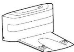
natural_image
Line drawing of a printer with a paper clip and clasp (no text or symbols)text_image
Technical diagram of a vacuum cleaner with numbered parts and labeled componentsnatural_image
Line drawing of a robotic vacuum cleaner with attached power outlet (no text or symbols)Fig. 1

text_image
1m 1m 2mFig. 2

Fig. 3

text_image
Diagram showing a remote control interface with hand placement, power switch, and device insertion stepFig. 4

natural_image
Line drawing of a robotic arm with attached cable and housing (no text or symbols)Fig. 5

natural_image
Diagram showing a hand inserting a device into a device with an arrow indicating the component (no text or symbols present)Fig. 6
natural_image
Line drawing of a hand inserting a circular button into a device component (no text or symbols)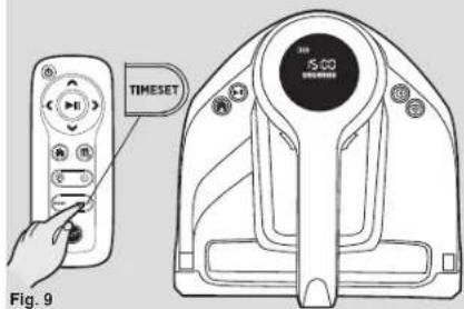
text_image
TIMESET 15:00 TIMESET Fig. 9
text_image
hOn Download on the App Store Google play App gallery 5:00 24:00 79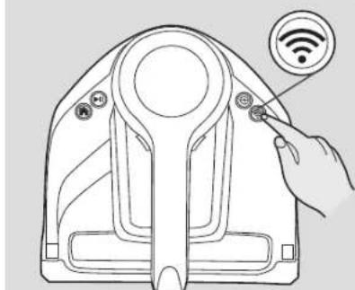
natural_image
Line drawing of a device's top view with a hand pointing to a sensor icon (no text or symbols present)ES

text_image
Diagram illustrating a device operation with labeled components including a play button, remote control, and audio output.Fig. 12

text_image
Diagram illustrating a device operation with labeled components and directional arrows indicating motion or feedback.Fig. 13

natural_image
Diagram showing a device being inserted into a remote control with an open lock icon (no text or symbols present)Fig. 14

natural_image
Technical line drawing of a mechanical clamp or bracket assembly (no text or symbols)Fig. 15

text_image
MODEFig. 16
natural_image
Diagram of a hand operating a robotic device with a handle, showing mechanical components and motion direction (no text or symbols)Fig. 17
natural_image
Illustration of hands exchanging a tray of small objects into a container (no text or symbols)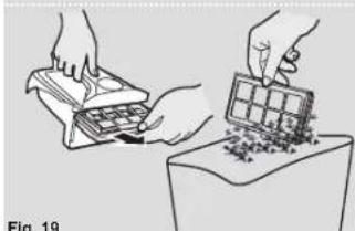
natural_image
Illustration of hands handling cards and a grid of items on a table (no text or symbols)Fig. 19
natural_image
Technical line drawing of a robotic vacuum cleaner with attached screw and blade assembly (no text or symbols)Fig. 20

natural_image
Line drawing of a hand using a tool to clean or adjust the internal components of an electronic device (no text or symbols visible)Fig. 21
natural_image
Diagram of a car interior showing internal components and a magnified inset of the handle (no text or symbols)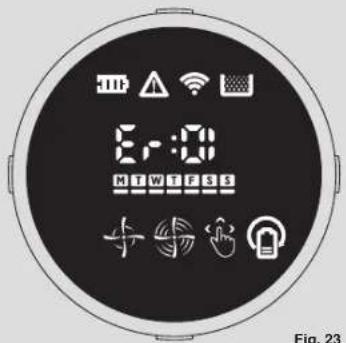
text_image
E:0 M T W F S S Figure 23Fig. 23
natural_image
Technical line drawing of a mechanical component with no visible text or symbols
natural_image
Line drawing of a printer with paper clip and paper holder (no text or symbols)Robotstøvsuger Lade station Fjernbetjening

X1 ekstra filter*
text_image
Technical diagram of a vacuum cleaner with numbered parts and labeled componentsnatural_image
Line drawing of a robotic vacuum cleaner with attached power outlet (no text or symbols)Fig. 1

text_image
1m 2m 1mFig. 2

Fig. 3

text_image
Diagram showing a remote control interface with labeled buttons and a device being inserted into a device.Fig. 4


natural_image
Line drawing of a robotic arm with attached cable and housing (no text or symbols)Fig. 5

natural_image
Diagram showing a hand operating a device with a close-up of its internal components (no text or symbols visible)Fig. 6
KLARG∅R DIN ROBOT ST∅VSUGER
EMBALLAGE
text_image
Diagram illustrating a device operation with labeled components including a play button, remote control, and audio output.Fig. 12

text_image
Diagram showing a hand holding a device with a circular indicator and plus symbol, alongside a circular diagram with an arrow indicating rotation or direction.Fig. 13

natural_image
Diagram showing a hand inserting a device into a remote control with an open lock icon (no text or symbols present)Fig. 14

natural_image
Technical line drawing of a mechanical clamp or bracket assembly (no text or symbols)Fig. 15
text_image
MODEFig. 16
MANUEL RENG∅RINGSTILSTAND
RENG∅RING AF ANTI-FALD SENSORER
text_image
E:0 M T W I F S S Fig. 23Fig. 23
FEJLFINDING
I det følgende vises en liste over de mest almindelige problemer og løsninger.
natural_image
Technical line drawing of a mechanical component with no visible text or symbols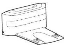
natural_image
Line drawing of a printer with a flat base and clasp (no text or symbols)
text_image
Technical diagram of a vacuum cleaner with numbered parts and labeled componentsnatural_image
Line drawing of a robotic vacuum cleaner with attached power outlet (no text or symbols)Fig. 1

text_image
1m 1m 2mFig. 2

Fig. 3

text_image
Diagram showing a remote control interface with hand buttons, power plug, and device with home control iconsFig. 4

natural_image
Line drawing of a robotic arm with attached cable and housing (no text or symbols)Fig. 5

natural_image
Illustration of a hand using a handheld device to install a small electronic device (no text or symbols visible)FORBERED ROBOT-RENGJ∅RINGSAPPARATET DITT
EMBALLASJE
Ikke kast Robotens emballasje. Det kan kreves for gyldigheten av garantien din i fremtiden.
text_image
Diagram illustrating a device operation with labeled components including a play button, remote control, and audio output.Fig. 12

text_image
Diagram showing a hand holding a device with a circular indicator and plus symbol, alongside a circular diagram with an arrow indicating rotation or direction.Fig. 13

natural_image
Diagram showing a hand inserting a device into a remote control with an open lock icon (no text or symbols present)Fig. 14

natural_image
Technical line drawing of a mechanical clamp or bracket assembly (no text or symbols)Fig. 15

text_image
MODEFig. 16
T∅MME ST∅VBEHOLDEREN
Etter støvsuging må du fjerne støvbeholderen.
natural_image
Diagram of a hand using a tool to lift a small mechanical component, showing internal structure and assembly (no text or symbols)Fig. 17
natural_image
Illustration of hands exchanging a tray with granular material on a base (no text or symbols)Fig. 18
natural_image
Illustration of hands exchanging a tray and a cube on a surface, with no visible text or symbolsFig. 19
natural_image
Technical line drawing of a robotic vacuum cleaner with attached screw and handle assembly (no text or symbols)Fig. 20
natural_image
Illustration of a hand placing a circular object onto a device casing (no text or symbols visible)Fig. 21
natural_image
Diagram of a computer monitor with an inset showing a hand holding a device (no text or symbols present)Fig. 22
text_image
8:00 M T W F S S Fig. 23Fig. 23
FEILS∅KING
natural_image
Technical line drawing of a mechanical component with no visible text or symbols
natural_image
Line drawing of a printer with a flat blade and clamped base (no text or symbols)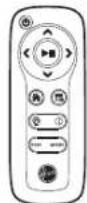
text_image
Technical diagram of a vacuum cleaner with numbered parts and close-up insets for component identificationtext_image
Technical diagram of a car interior with numbered components for identification| 16 Bakhjul |
| 17 Drivhjul |
| 18 Ladd Kontakter |
natural_image
Line drawing of a robotic arm with attached power outlet and cable, no text or symbols presentFig. 1
text_image
1m 1m 2mFig. 2

Fig. 3

text_image
Diagram showing a remote control interface with hand placement, power switch, and device insertion stepFig. 4


natural_image
Line drawing of a robotic arm with attached cable and housing (no text or symbols)Fig. 5

natural_image
Diagram showing a hand operating a device with a close-up view of the internal components (no text or symbols present)Fig. 6
FÖRBERED DIN ROBOTDAMMSUGARE
FÖRPACKNING
text_image
Diagram illustrating a device operation with labeled components including a play button, remote control, and audio output.Fig. 12

text_image
Diagram showing a hand holding a device with a circular indicator and plus symbol, alongside a circular diagram with an arrow indicating rotation or direction.Fig. 13

natural_image
Diagram showing a device being inserted into a remote control with an open lock icon (no text or symbols present)Fig. 14

natural_image
Technical line drawing of a mechanical clamp or bracket assembly (no text or symbols)Fig. 15

text_image
MODEFig. 16
Rengöringsprogram
text_image
E:0 M T W I F S S Figure 23Fig. 23
FELSÖKNING
natural_image
Technical line drawing of a mechanical component with no visible text or symbols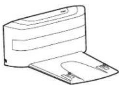
natural_image
Line drawing of a printer with a flat base and clasp (no text or symbols)text_image
Technical diagram of a vacuum cleaner with numbered parts and close-up insets for component identificationnatural_image
Line drawing of a robotic vacuum cleaner with a power outlet, no text or symbols present
text_image
1m 2m 1mKuva 2

Kuva 3

text_image
Diagram showing a remote control device with labeled buttons and an open device, illustrating the operation of switching from a button to a device.Kuva 4


natural_image
Line drawing of a robotic arm with attached sensor and cable (no text or symbols)Kuva 5

natural_image
Illustration of a hand using a device to adjust or install a small electronic device (no text or symbols visible)ROBOTTI-IMURIN VALMISTELEMINEN
PAKKAUS
text_image
Diagram illustrating a device operation with labeled components including a play button, remote control, and audio output.Kuva 12
text_image
Diagram illustrating a device operation with labeled components and directional arrows, including a hand interacting with a control panel.Kuva 13

text_image
Diagram showing a device being inserted into a remote control via a lock icon, with a hand holding the lock.Kuva 14

natural_image
Technical line drawing of a mechanical clamp or bracket assembly (no text or symbols)Kuva 15

text_image
MODEKuva 16
Puhdistusohjelmat
FULL & GO -PUHDISTUSTILA
MANUAALINEN PUHDISTUSTILA
PÖLYSÄILIÖN TYHJENNYS
text_image
6:00 M T W F S S Kuya 23VIANMÄÄRITYS
natural_image
Technical line drawing of a mechanical component with no visible text or symbols
natural_image
Line drawing of a printer with a flat base and clamped cover (no text or symbols)text_image
Technical diagram of a vacuum cleaner with numbered parts and component highlightsnatural_image
Line drawing of a robotic vacuum cleaner inside a room, showing mechanical components and wiring (no text or symbols)Рис.1
text_image
1m 2m 1mРис. 2
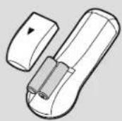
Рис. 3

text_image
Diagram showing a remote control interface with hand buttons, power plug, and device insertion stepРис. 4


natural_image
Line drawing of a robotic arm with attached cable and housing (no text or symbols)Рис. 5

natural_image
Illustration of a hand using a device to install a small electronic component (no text or symbols visible)Рис. 6
natural_image
Line drawing of a hand holding a small circular component, next to a mechanical device (no text or symbols)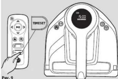
text_image
TIMESET 15:00 Рис. 9
text_image
hOn Download on the App Store Google play ADOISE IT ON AppGallery 15:00 2023Рис. 10
text_image
Diagram showing a hand interacting with a device labeled 'Wi-Fi' and a sensor icon, likely illustrating wireless signal or sensor interface.Рис. 11
RU

text_image
Diagram illustrating a device operation with labeled components including a play button, remote control, and audio output.Рис. 12

text_image
Diagram illustrating a device operation with labeled components and directional arrows indicating motion or feedback.Рис. 13

natural_image
Illustration of a remote control device with a lock icon and cable connector (no text or symbols)Рис. 14

natural_image
Technical line drawing of a mechanical clamp or bracket assembly (no text or symbols)Рис. 15

text_image
MODEРис. 16
Программы уборки
text_image
E:0 M T W F S S + + - Pc. 23natural_image
Technical line drawing of a mechanical component with no visible text or symbols
natural_image
Line drawing of a printer with a flat base and clamped paper attachment (no text or symbols)text_image
Technical diagram of a vacuum cleaner with numbered parts and close-up insets for component identificationnatural_image
Line drawing of a robotic vacuum cleaner inside a room, showing mounting bracket and wiring (no text or symbols)Eik.1

text_image
1m 2m 1mEik.2

Eik.3

text_image
Diagram showing a remote control interface with hand buttons, power plug, and device with home control iconsEik.4


natural_image
Line drawing of a robotic arm with attached power outlet (no text or symbols)Eik.5

natural_image
Illustration of a hand using a tool to adjust or install a device into a device casing (no text or symbols visible)Eik.6
text_image
Diagram illustrating a device operation with labeled components including a play button, remote control, and audio output.Eik. 12

text_image
Diagram illustrating a device operation with labeled components and directional arrows indicating rotation or movement.Eik. 13

natural_image
Diagram showing a device being inserted into a remote control with an open lock icon (no text or symbols present)Eik.14

natural_image
Technical line drawing of a mechanical clamp or bracket assembly (no text or symbols)Eik.15

text_image
MODEEik. 16
natural_image
Diagram of a hand operating a robotic device with an arrow indicating motion (no text or symbols present)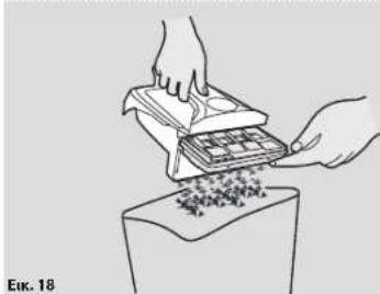
natural_image
Illustration of hands exchanging a tray of small objects into a container (no text or symbols)
natural_image
Illustration of hands exchanging a tray and a grid on a table, with no visible text or symbols
natural_image
Technical line drawing of a robotic vacuum cleaner with attached screw and handle assembly (no text or symbols)Eik. 20
natural_image
Illustration of a hand using a tool to clean or repair electronic components on a device (no text or symbols visible)
text_image
Eik. 22
text_image
E:0 M T W F S S Erik. 23natural_image
Technical line drawing of a mechanical device with no visible text or symbols
natural_image
Line drawing of a printer with a flat base and clamped paper (no text or symbols)text_image
Technical diagram of a vacuum cleaner with numbered parts and component highlightsnatural_image
Line drawing of a robotic vacuum cleaner with attached power outlet, no text or symbols presentRys.1

text_image
1m 2m 1mRys. 2

Rys. 3

text_image
Diagram showing a remote control interface with hand placement, power switch, and device insertion stepRys. 4


natural_image
Line drawing of a robotic arm with attached cable and housing (no text or symbols)Rys. 5

natural_image
Illustration of a hand using a tool to adjust or install a device inside a vehicle (no text or symbols visible)Rys. 6
PRZYGOTOWANIE ROBOTA-ODKURZACZA
PAKOWANIE
text_image
Diagram illustrating a device operation with labeled components including a play button, remote control, and audio output.Rys. 12

text_image
Diagram showing a hand interacting with a device labeled 'Bv' and a circular diagram with an arrow indicating rotation or transformation.Rys. 13
natural_image
Illustration of a remote control device with a lock icon and cable connector (no text or symbols)Rys. 14
natural_image
Technical line drawing of a mechanical clamp or bracket assembly (no text or symbols)Rys. 15

text_image
MODERys. 16
Programy czyszczące
natural_image
Technical line drawing of a mechanical device with no visible text or symbols
natural_image
Line drawing of a printer with a flat base and clamped cover (no text or symbols)text_image
Technical diagram of a vacuum cleaner with numbered parts and close-up insets for component identificationnatural_image
Line drawing of a robotic vacuum cleaner inside a room, showing mechanical components and a wall-mounted power outlet (no text or symbols)
text_image
1m 1m 2mObr. 2

Obr. 3
text_image
Diagram showing a remote control interface with hand placement, power switch, and device insertion stepObr. 4


natural_image
Line drawing of a robotic arm with attached cable and housing (no text or symbols)Obr.5

natural_image
Diagram showing a hand operating a device with a close-up of its internal components (no text or symbols visible)PŘIPRAVTE SVŮJ ROBOTICKÝ VYSAVAČ
BALENÍ
text_image
Obr. 7 Obr. 8 Obr. 9 TIMESET 5:00 hOn Downloaded on the App Store Google play app gallery S-00 147CZ

text_image
Diagram illustrating a device operation with labeled components including a play button, remote control, and audio output.Obr. 12
text_image
Diagram illustrating a device operation with labeled components and directional arrows indicating motion or feedback.Obr. 13

natural_image
Illustration of a remote control device with an open button and cable, showing no text or symbolsObr. 14

natural_image
Technical line drawing of a mechanical clamp or bracket assembly (no text or symbols)Obr. 15

text_image
MODEObr. 16
Programy čištění
text_image
E:0 M T W F S S + + + + + + Obr. 23ŘEŠENÍ POTÍŽÍ
NAVODILA ZA VARNO UPORABO
natural_image
Technical line drawing of a mechanical component with no visible text or symbols
natural_image
Line drawing of a printer with a clasp and paper holder (no text or symbols)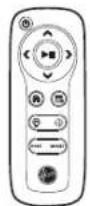
text_image
Technical diagram of a vacuum cleaner with numbered parts and close-up insets for component identificationnatural_image
Line drawing of a robotic vacuum cleaner with attached power outlet, no text or symbols present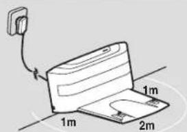
text_image
1m 1m 2mSlika 2

Slika 3

text_image
Diagram showing a remote control interface with hand placement, power switch, and device insertion stepSlika 4

natural_image
Line drawing of a robotic arm with attached cable and housing (no text or symbols)Slika 5

natural_image
Illustration of a hand using a device to adjust or install a small electronic device (no text or symbols visible)PRIPRAVITE SVOJ ROBOTSKI SESALNIK
EMBALAŽA
text_image
Diagram illustrating a device operation with labeled components including a play button, remote control, and audio output.Slika 12

text_image
Diagram illustrating a sewing machine operation with labeled parts and directional arrows indicating cycle or direction.Slika 13

natural_image
Illustration of a remote control device with an open lock icon and cable connector (no text or symbols)Slika 14

natural_image
Technical line drawing of a mechanical clamp or bracket assembly (no text or symbols)Slika 15

text_image
MODESlika 16
text_image
8:00 M T W F S S Slika 23ODPRAVLJANJE TEŽAV
natural_image
Technical line drawing of a mechanical component with no visible text or symbols
natural_image
Line drawing of a printer with a clasp and paper holder (no text or symbols)text_image
Technical diagram of a vacuum cleaner with numbered parts and close-up insets for component identificationnatural_image
Line drawing of a robotic vacuum cleaner inside a room, with a power outlet and cable attachment (no text or symbols)
text_image
1m 2m 1mŞek. 1
text_image
Diagram illustrating remote control device installation steps with labeled components and a robotic device.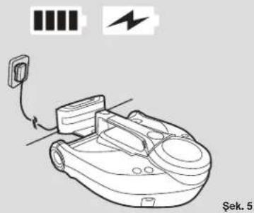
natural_image
Line drawing of a robotic device with battery, power cord, and battery icon (no text or symbols)
natural_image
Illustration of a hand using a device to adjust or install a small electronic component (no text or symbols visible)Şek. 6
ROBOT SÜPÜRGENİZİN HAZIRLANMASI
PAKETLEME
text_image
Diagram illustrating a device operation with labeled components including a play button, remote control, and audio output.Şek. 12

text_image
Diagram illustrating a device operation with labeled components and directional arrows indicating motion or feedback.Şek. 13

natural_image
Diagram showing a device being inserted into a remote control with an open lock icon (no text or symbols present)Şek. 14

natural_image
Technical line drawing of a mechanical clamp or bracket assembly (no text or symbols)Şek. 15

text_image
MODEŞek. 16