HF310P 001 - Vacuum Cleaner HOOVER - Free user manual and instructions
Find the device manual for free HF310P 001 HOOVER in PDF.

User questions about HF310P 001 HOOVER
0 question about this device. Answer the ones you know or ask your own.
Ask a new question about this device
Download the instructions for your Vacuum Cleaner in PDF format for free! Find your manual HF310P 001 - HOOVER and take your electronic device back in hand. On this page are published all the documents necessary for the use of your device. HF310P 001 by HOOVER.
USER MANUAL HF310P 001 HOOVER
natural_image
3D rendering of a black and white vacuum cleaner with extended shaft and ventilation slots (no text or symbols visible)PRODUCTCOMPONENTS:
A. On/OffButton
B. ModeButton
C. LEDDisplay
D. DustBin
E. BinFlap Release Button
F. Dust Bin Release Button
G. Integrated Dusting Brush
H. Handheld Release Button
I. Tube*
J. Flexi Tube Release Button
K. FlexiTube*
L. Nozzle Brushbar Release Slider
M. Nozzle Front Led Light
N. Nozzle
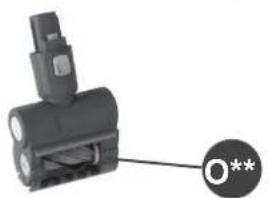
O. MotorisedPetTool
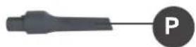
P. CreviceTool
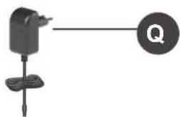
Q. Charger
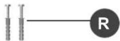
R. Wall Mount Screws
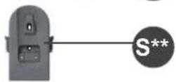
S. WallMount
T. Hanger1*
U. Hanger 2*
V. Battery Pack
W. Battery Charging indicator
X. Battery Release Button
Y. ExhaustFilter
Z. Filter(2pcs*)
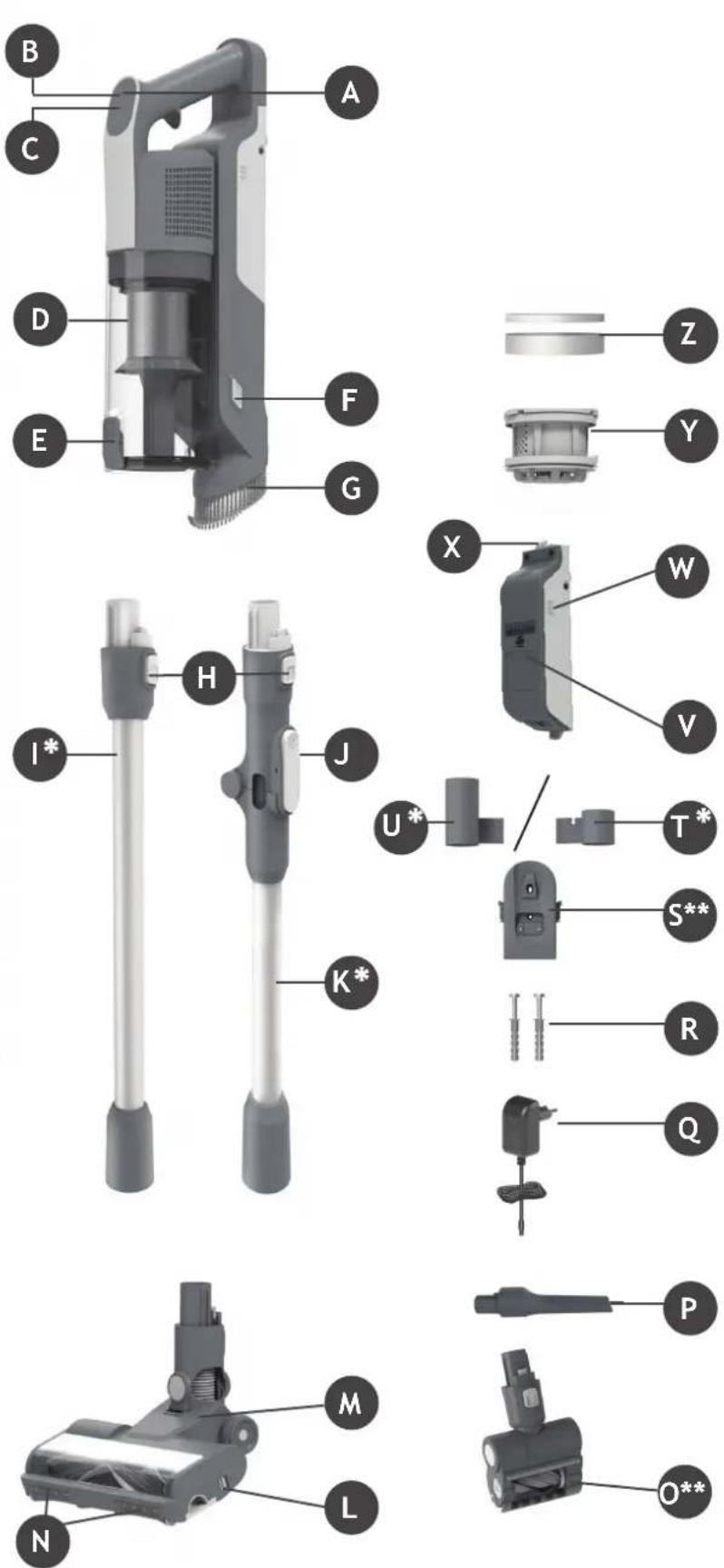
text_image
Exploded view diagram of a vacuum cleaner with labeled parts from B to O*** Certain Models Only ** Shape design may vary according to models
2. PREPARING YOUR CLEANER
Remove all product parts from the packaging and assemble your cleaner.
STEP1: Fit the tube into the floor nozzle.
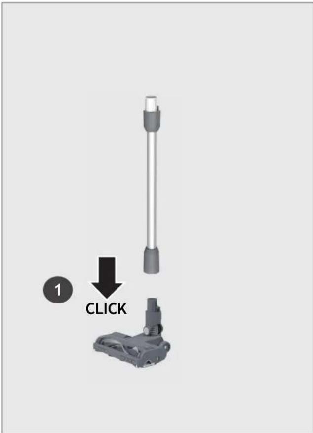
text_image
1 CLICKSTEP 2: Fit the handheld unit onto the tube.
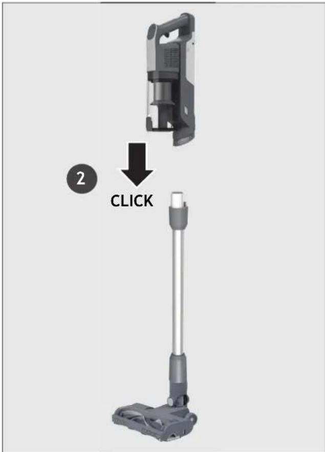
text_image
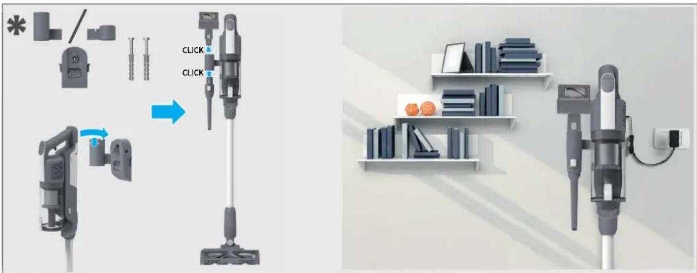
2 CLICKSTEP3: We provide a wall mount for optional storage.
If you wish to use it please proceed to assembly. Attach the Hanger to the Wall mount on the left or side right (depending on your model), slide it until you hear "click".
Fix the wall mount to the wall using the two screws provided.
All accessories can be attached to the wall mount. Attach them to the hangers until you hear it "click" into location. Insert charger into charger inlet located on the wall mount to automatically charge your vacuum cleaner every time you hang it on the wall mount.
text_image
Diagram illustrating the process of a vacuum cleaner's cleaning and installation, showing step-by-step assembly and final assembly.3. CHARGING THE BATTERY
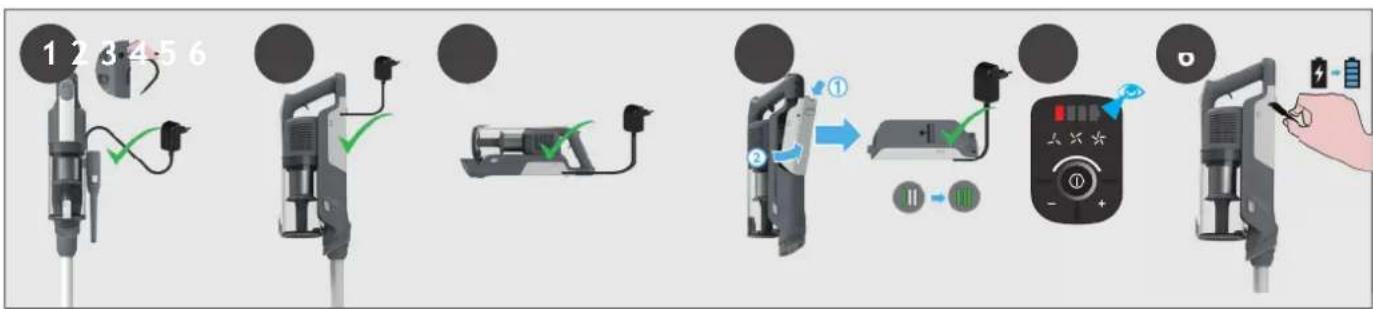
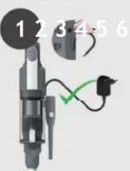
The battery of your product does not come fully charged. Before first use, please charge your product completely. It takes around 3.5 hours.
For your convenience, the battery can be charged in 4 different conditions.
- With the product fully assembled located on the wall mount, the battery status will be indicated on the LED display.
- With the product fully assembled in stick mode, the battery status will be indicated on the LED display.
- With the product in handheld mode, the battery status will be indicated on the LED display.
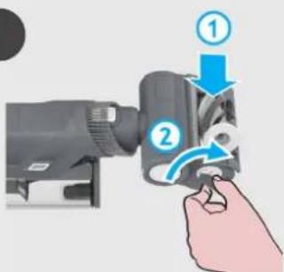
- Remove the battery from the product by pressing the battery release buttons.
Insert the battery charger jack to the battery. The battery pack LED will illuminate to show charging level.
When using your product, the real time charge level of your battery is indicated on the LED display. When the remaining battery is lower than 20%, the battery icon on the display will blink in white (5). It is recommended you switch off your product and recharge battery (6).
NOTE: It is normal for the charger to become warm to touch when charging. Use only the charger supplied with your product.
flowchart
graph LR
    A["12/3/4/5/6"] --> B["Device with cable"]
    B --> C["Device with plug"]
    C --> D["Device with power plug"]
    D --> E["Device with switch"]
    E --> F["Device with battery and hand action"]
    F --> G["Device with hand, battery, and hand action"]
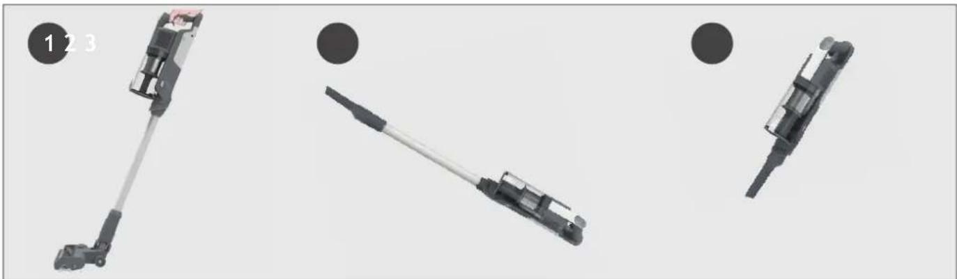
4. USING YOUR CLEANER
There are 3 different working modes for your cleaner:
- Stick mode.
- Above Floor mode.
- Handheld mode.
natural_image
Three mechanical components with numbered callouts, shown from different angles (no text or symbols on parts)* Dependant on your model.
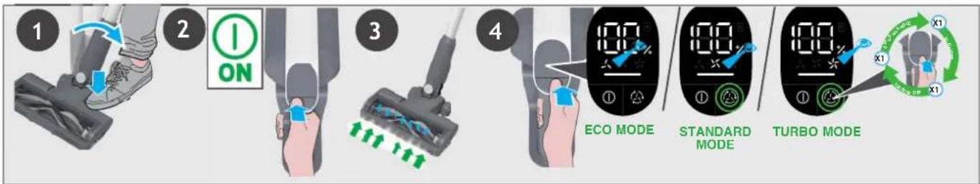
4.1 STICK MODE
To use your product in Stick mode:
- Place your foot on the nozzle and pull back to recline the tube.
- Press the On/Off power button to begin cleaning.
NOTE: The nozzle LED lights are always on and the brushbar is always rotating.
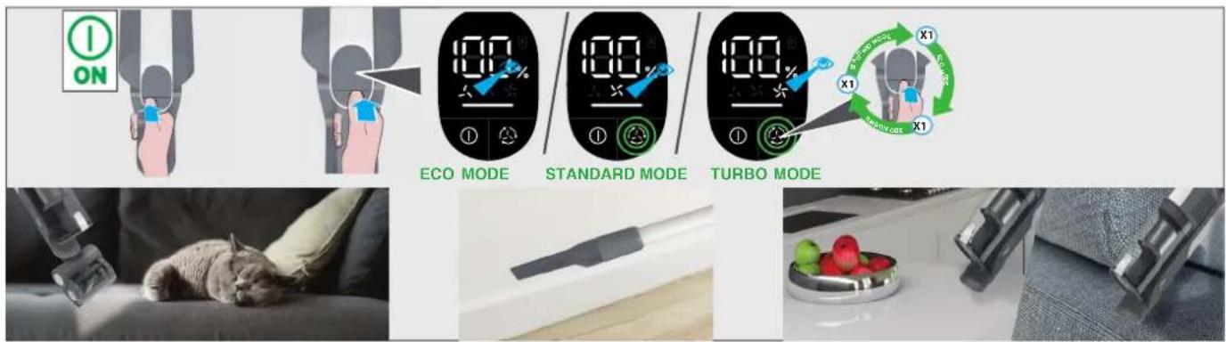
By pressing the mode button you can easily switch between the three cleaning modes (STANDARD, TURBO, ECO) depending on the cleaning task.
The corresponding icon will light up on the LED display screen to show you the current mode.
If you require a deeper clean when using your product in Stick mode, press the switch button until the turbo icon is on to increase the power.
The turbo icon will illuminate on the LED display to confirm your selection.
Please note this will reduce your battery runtime.
flowchart
graph TD
    A["Step 1: Hand press"] --> B["Step 2: On/OFF/ON signals"]
    B --> C["Step 3: Trigger mechanism"]
    C --> D["Step 4: ECO mode activation"]
    D --> E["Step 5: Standard mode activation"]
    E --> F["Step 6: Turbo mode activation"]
    F --> G["End: Turnover cycle with X1 and X2 indicators"]
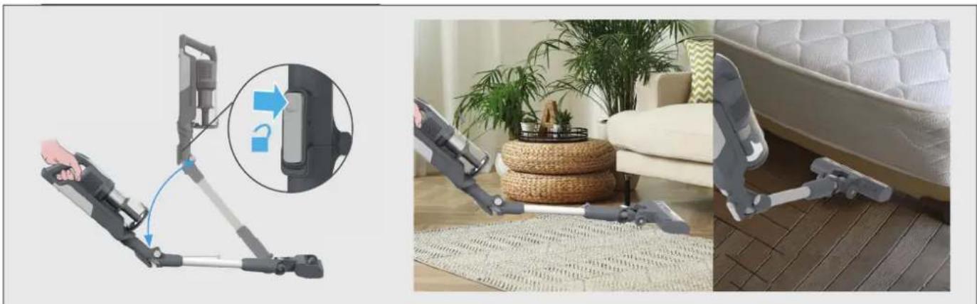
4.1.1FLEXIBLEMODE \*
If you want to easily access hard-to-reach areas under furniture, press the fl exible tube release button to position the tube to a lower angle.
natural_image
Three-panel image showing a robotic device with a close-up inset of the device's handle, alongside a photo of a baby washing machine on a patterned rug in a living room setting.4.2 ABOVE FLOOR / HANDHELD MODE
To use your product in Above Floor mode:
- Remove the tube from the nozzle by pressing the nozzle release button and pull the tube from the floor nozzle.
- Fit your desired accessory to the end of the tube. All of your available accessories will fit onto the end of the tube.
- Press the On/Off power button to begin cleaning.
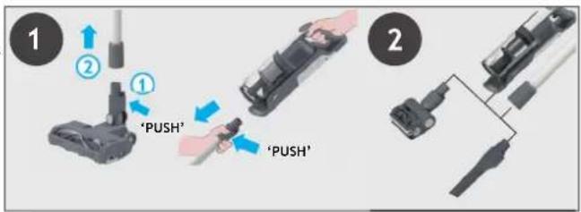
text_image
1 2 ① 'PUSH' 'PUSH' 2To use your product in handheld mode :
- Remove the Handheld unit from the tube by pressing the handheld release button and pulling apart.
- Fit your desired accessory to the end of the handheld unit.
All of your available accessories will fit onto the end of the handheld unit. - Press the On/Off power button to begin cleaning.
By pressing the mode button you can easily switch between the three cleaning modes (STANDARD, TURBO, ECO) depending on the cleaning task.
The corresponding icon will light up on the LED display screen to show you the current mode.
text_image
I ON ECO MODE STANDARD MODE TURBO MODE X1 X1 X1 SARSO-DRAGON SARSO-DRAGON X1 X1 X15. CLEANER MAINTENANCE
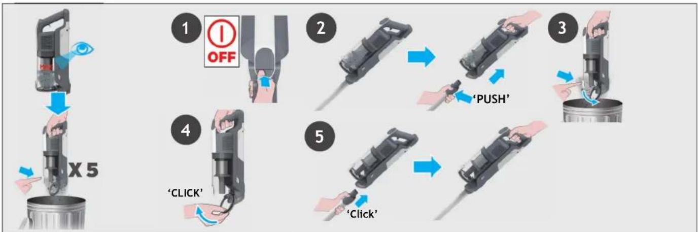
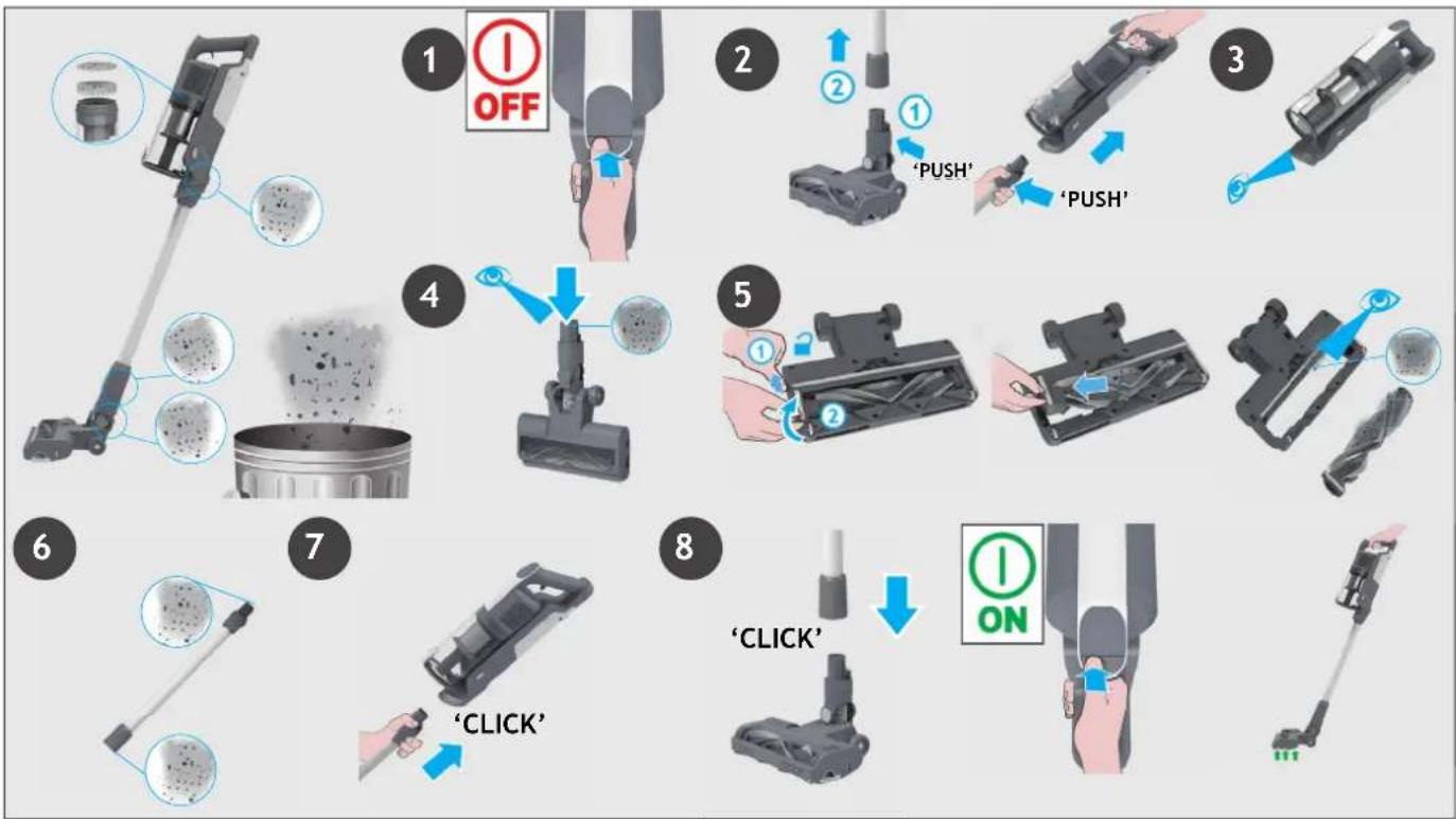
5.1 EMPTYING THE DUST BIN
NOTE: It is recommended to empty the dust bin after each use or when dust is up to the max fill line.
- Ensure your product is switched off.
- Press the Handheld release button and remove the handheld unit from the tube.
- Hold the handheld over a bin and press the bin fl ap release button to open the fl ap and release the debris into the trash.
- Close the dust bin fl ap, you will hear a click when fully locked.
- Re-Assemble your product.
flowchart
graph TD
    A["1 OFF"] --> B["2"]
    B --> C["3"]
    C --> D["4"]
    D --> E["5"]
* Dependant on your model.
5. CLEANER MAINTENANCE
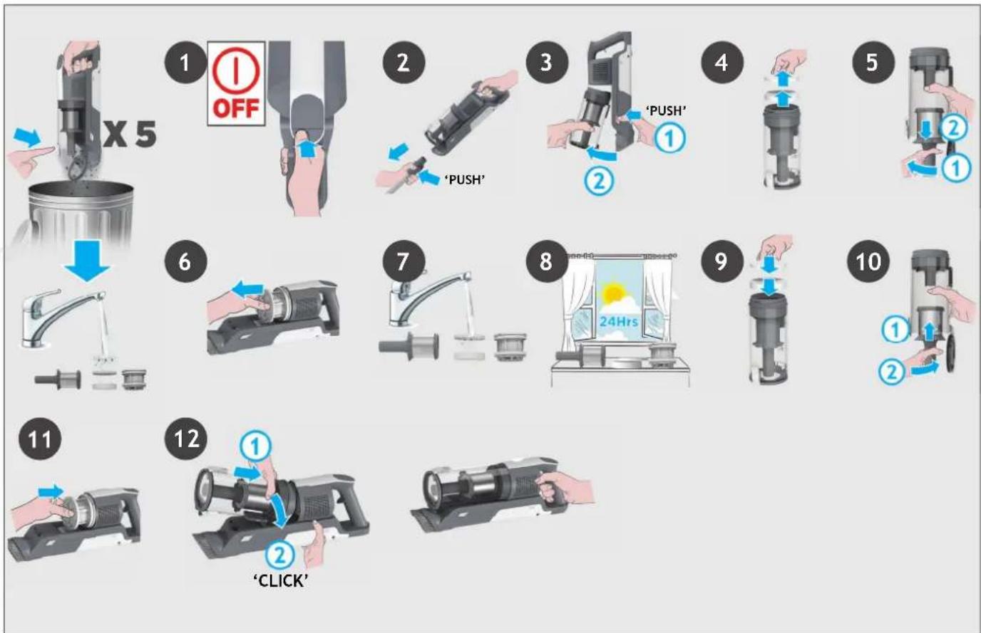
5.2 FILTERS
IMPORTANT: For optimum performance, we recommend to wash the filters after every 5 bin empties.
- Ensure your product is switched off.
- Press the handheld release button and remove the handheld unit from the tube.
- Press the bin release button and remove the bin assembly from the handheld unit.
- Remove the filters from the bin and separate the different parts.
- Remove the metal mesh fi lter by turning it anti-clockwise.
- Pull out the exhaust filter from the handheld.
- Wash the filters and the bin using lukewarm water.
- Leave them to dry for 24hrs before refi tting to your product.
- Refi t the fi lter back in the dust bin in their original position.
- Re-assemble the mesh filter into the dust bin by rotating it clockwise until you hear a "click" sound. Close the bin fl ap.
- Reinsert the exhaust filter into the handheld.
- Reinsert the dust bin onto the handheld until you hear a "click" sound.
NOTE: Do not use hot water or detergents when cleaning the filters. In the unlikely event of the filters becoming damaged, fi t a genuine Hoover replacement.
flowchart
graph TD
    A["1: OFF"] --> B["2: PUSH"]
    B --> C["3: PUSH"]
    C --> D["4: Push"]
    D --> E["5: Push"]
    E --> F["6: Push"]
    F --> G["7: Push"]
    G --> H["8: Push"]
    H --> I["9: Push"]
    I --> J["10: Push"]
    J --> K["11: Push"]
    K --> L["12: Push"]
5. CLEANER MAINTENANCE
5.3 FLOOR NOZZLE
GB
Thanks to ANTI-TWIST, your Hoover vacuum features an integrated comb which reduces hair wrapping around the brushbar. However, if your cleaner is not picking up effi ciently your brushbar may need to be cleaned.
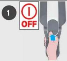
- Ensure your product is switched off.
- Move the nozzle brushbar release slider to the left and pull out the agitator.
- Remove any excess debris from the brushbar. Check for and remove any large debris from inside the nozzle.
- Re-insert the brushbar into the nozzle ensuring it is in the correct position and push down at the end of the brushbar until you hear it "CLICK" to lock in position.
- Re-assemble the nozzle onto the product.
text_image
1 OFF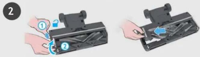
text_image
Diagram showing two-step installation of a mechanical device with labeled parts and directional arrows indicating motion.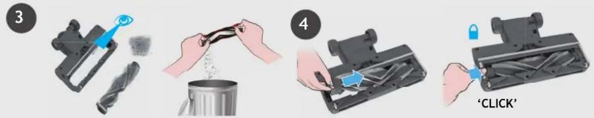
text_image
3 4 'CLICK'5. CLEANER MAINTENANCE
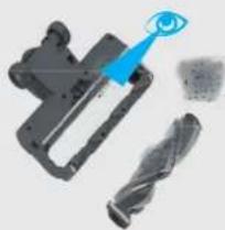
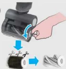
5.4MOTORISEDPETTOOL
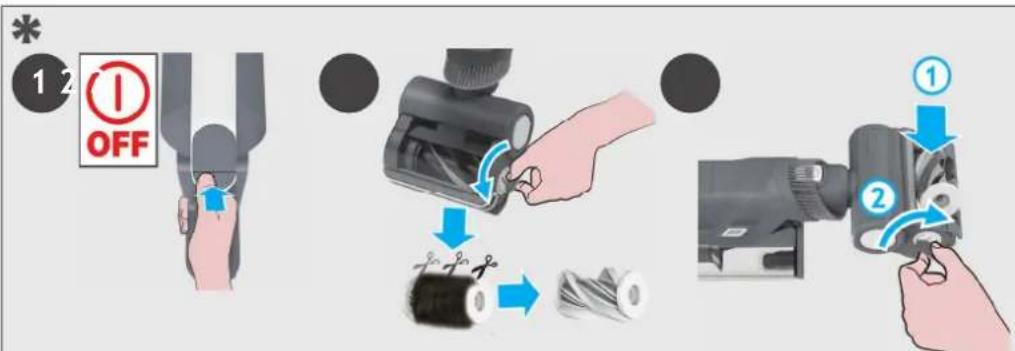
- Ensure your product is switched off, detach the motorised pet tool from your product.
- Using a coin, open the brushbar release lock and remove the brush bar.
Using scissors, remove any tangled fi bres or debris from the brushbar. Look inside the nozzle and remove any debris.
- Refi t the brushbar and using a coin, lock into position.
text_image
12 OFF ① ②5. CLEANER MAINTENANCE
5.5 BLOCKAGES
GB
If your product is still working but has low or no suction, or if the brushbar is not rotating, you may have a blockage. A red light will appear on the battery charging indicator.
Carry out all maintenance instructions included in sections, 5.1, 5.2, 5.3, 5.4.
The following additional areas of your product should also checked for any debris or blockages:
- Ensure your product is switched off.
- Separate the Floor nozzle, tube and handheld unit as per previous instructions.
- Visually check the handheld inlet connection area for any debris or obstructions and clean it.
- Position the nozzle neck vertically and visually check for any debris or obstructions and clean it.
- Remove the brushbar and check the nozzle inlet area for any debris or obstructions and clean it.
- Visually check both ends of the tube and remove any debris or obstructions.
- Re-Assemble your product.
flowchart
graph TD
    A["1 OFF"] --> B["2 PUSH"]
    B --> C["3 PUSH"]
    C --> D["4 PUSH"]
    D --> E["5 PUSH"]
    E --> F["6 CLK"]
    F --> G["7 CLICK"]
    G --> H["8 ON"]
6. TROUBLE SHOOTING
Should you have any problem with your cleaner, follow this simple check list before calling the Hoover Customer Service Centre.
A. Cleaner does not switch on.
Check if the cleaner is charged.
Check if the battery pack is assembled in place.
B. Cleaner stop working.
Check if there is an obstruction in air inlet or in the tube, clear it and ensure the product is OFF.
Once this is done simply press the on/off button, the product will start working again.
C. The Nozzle stops working and E1 appears on the display.
There is a blockage in the nozzle or an obstruction to the brush bar. Ensure your product is switched OFF and remove any debris or obstruction and follow cleaner maintenance 5.3 instructions.
D. Batteries cannot be charged.
This may be a result of very long storage periods (over half year).
Contact Hoover customer service to arrange battery replacement.
If the problem persists, contact the Hoover customer service center.
Disposal of the packing material
The Packaging is designed to protect the appliance from damage during transportation. The packaging materials used are selected from materials which are environmentally friendly for disposal and should be recycled. Recycling the packaging reduces the use of raw materials in the manufacturing process and also reduces the amount of waste in landfill sites.
Replacing and disposing the Batteries
This cleaner is fitted with a rechargeable lithium-ion battery pack which is replaceable.
WARNING: Only use approved replacement parts for your cleaner. Using parts not validated by hoover are dangerous and will invalidate your guarantee.
WARNING: Do not try to open the battery pack and repair it by yourself.
-
Press the battery release buttons and pull the battery outside.
-
Removed the old battery pack and replace with the new battery pack.
-
Dispose of the batteries safely. Used batteries should be taken to a recycling station and not disposed of with household waste.
HOOVER SPARES AND CONSUMABLES
Always replace parts with genuine Hoover spares. These are available from your local Hoover dealer or direct from Hoover.
When ordering parts always quote your model number.
YOUR GUARANTEE
The guarantee conditions for this appliance are as defined by our representative in the country in which it is sold. Details regarding these conditions can be obtained from the dealer from whom the appliance was purchased. The bill of sale or receipt must be produced when making any claim under the terms of this guarantee.
IMPORTANT: the battery in this cleaner is guaranteed for 1 year from the date of purchase.
After 1 year the customer is liable for the cost of a new battery.
The following codes may appear during use or on start up.
| Code Failure Explanation | |
| E1 | Debris obstruction in the nozzle or in the motorised pet tool*. See “CLEANER MAINTENANCE” 5.3 and 5.4. |
| E2 | Debris blocking the tubee, please see “CLEANER MAINTENANCE” 5.5.If it still doesn’t work, please contact the Hoover customer service. |
| E3 | Battery in over heating. Remove battery pack from the product and let it cool for some time, then re-assemble to the product. If it still doesn’t work, please contact the Hoover customer service. |
| E4 | Please contact the Hoover customer service. |
| E5 | |
ATTENTION: If any of these failures persist, contact the Hoover customer service. DO NOT try to disassemble the product by yourself.
COMPOSITION DU PRODUIT:
text_image
Exploded view diagram of a vacuum cleaner with labeled parts from B to O**natural_image
Three black-and-white diagrams showing mechanical components with no visible text or symbolsnatural_image
Product photos showing a hand holding a remote control device and a virtual vacuum cleaner in a living room setting (no text or symbols visible)4.2 MODE HORS-SOL/ ASPIRATEUR À MAIN
text_image
Exploded view diagram of a vacuum cleaner with labeled parts from B to O**text_image
Diagram illustrating the installation of a vacuum cleaner with labeled components and directional arrows, alongside its interior shelf setup.3. AKKU AUFLADEN
DE
natural_image
Three mechanical components with numbered callouts, shown from different angles (no text or symbols on parts)flowchart
graph TD
    A["1: Leg in foot"] --> B["2: ON"]
    B --> C["3: Screw switch"]
    C --> D["4: ECO-MODUS"]
    D --> E["5: Standard-MODUS"]
    E --> F["6: Turbo-MODUS"]
4.1.1FLEXIBLERMODUS \*
natural_image
Three-panel image showing a robotic device with a close-up inset of the device's handle, and a photo of a baby washing machine on a rug in a living room setting (no text or symbols visible)4.2ÜBERBODEN/HANDGERÄT-MODUS
text_image
1 OFF 2 3 4 "KLICK"text_image
Exploded view diagram of a vacuum cleaner with labeled parts from B to O**2. PREPARAZIONE DELL'APPARECCHIO
IT
text_image
Diagram illustrating the process of cleaning a vacuum cleaner with labeled buttons and instructionsnatural_image
Three mechanical components with numbered callouts, shown from different angles (no text or symbols present)4.1 MODALITÀ STANDARD
IT
natural_image
Two-panel image showing a robotic device with a close-up inset of the handle and a close-up of its backrest in a cozy living room (no text or symbols visible)4.2 MODALITÀ PER RIPIANI / PORTATILE
IT
text_image
Exploded view diagram of a vacuum cleaner with labeled parts from B to O**text_image
Diagram illustrating the installation of a KLIK vacuum cleaner with its internal components and assembly process.3. DE BATTERIJ OPLADEN
flowchart
graph LR
    A["1 2 3 4 5 6"] --> B["Chamber with power source"]
    B --> C["Chamber connected to power supply"]
    C --> D["Switch: ①"]
    D --> E["Control panel with battery, switch, power, and controller"]
    E --> F["Hand inserting battery into terminal device"]
4. UW STOFZUIGER GEBRUIKEN
natural_image
Three mechanical components with numbered callouts, shown from different angles (no text or symbols on parts)4.1 STEELSTOFZUIGER MODUS
flowchart
graph TD
    A["Step 1: Boot with hand press"] --> B["Step 2: On/OFF/ON signals"]
    B --> C["Step 3: Hand press with brake lever"]
    C --> D["Step 4: ECO-MODUS mode switching"]
    D --> E["Step 5: Standard Mode with ECO-MODUS"]
    E --> F["Step 6: Turbo Mode switching with X1/2 indicators"]
4.1.1FLEXIBELEMODUS \*
natural_image
Three-panel image showing a hand holding a remote control device, a close-up of the device with blue arrows indicating rotation, and a photo of a vacuum cleaner on a patterned rug in a cozy living room.4.2 BOVEN DE VLOER / HANDMODUS
NL
text_image
Exploded view diagram of a vacuum cleaner with labeled parts from B to O**text_image
Diagram illustrating the installation of a vacuum cleaner with labeled components and airflow direction, alongside its interior shelf setup.flowchart
graph LR
    A["1:2:3:4:5:6"] --> B["Respirator"]
    B --> C["Respirator with cable"]
    C --> D["Respirator with power plug"]
    D --> E["Respirator with switch"]
    E --> F["Respirator with battery"]
    F --> G["Remote Control with ① + ② + ③ + ④ + ⑤"]
    G --> H["Hand inserting battery into remote control"]
4. UTILIZAR O SEU ASPIRADOR
natural_image
Three mechanical components with numbered callouts, shown from different angles (no text or symbols on parts)4.1 MODO VERTICAL
PT
natural_image
Three-panel image showing a hand holding a remote control device, a close-up of a vacuum cleaner with blue arrows indicating rotation, and a close-up of a bed mat on the floor (no text or symbols visible)4.2 ACIMA DO PAVIMENTO /MODO PORTÁTIL
text_image
Exploded view diagram of a vacuum cleaner with labeled parts from B to O**natural_image
Three mechanical components with numbered callouts, shown from different angles (no text or symbols on parts)natural_image
Three-panel image showing a robotic device with a close-up inset of the device's handle, and a photo of a baby washing machine on a rug in a cozy living room (no text or symbols visible)text_image
Exploded view diagram of a vacuum cleaner with labeled parts from B to O**text_image
Diagram illustrating the installation of a KLIK vacuum cleaner with its internal components and assembly process, alongside a photo of its own shelf.3. OPLADNING AF BATTERIET
DK
flowchart
graph LR
    A["1 2 3 4 5 6"] --> B["Chamber with power plug"]
    B --> C["Chamber with charging plug"]
    C --> D["Switch to power source"]
    D --> E["Switch to controller"]
    E --> F["Hand inserting battery into controller"]
4. BRUG AF ST∅VSUGEREN
natural_image
Three mechanical components with numbered labels (1, 2, 3) shown in separate views, no text or symbols present.For at bruge dit produkt i stick-tilstand:
natural_image
Three-panel image showing a hand holding a remote control device, a close-up of the device with blue arrows indicating rotation, and a photo of a baby washing machine on a patterned rug in a cozy living room.4.2 OVER GULV / HÅNDHOLDT
text_image
1 OFF 2 3 4 "KLIK"5. VEDLIGEHOLDELSE AF ST∅VSUGEREN
5.4 MOTORISERET VÄRKT∅J TIL KÆLEDYR\*
text_image
Exploded view diagram of a vacuum cleaner with labeled parts from B to O**text_image
Diagram showing a handwashing robot with KLIKK-branded components and a wall-mounted shelf with books and appliances.3. LADING AV BATTERIET
flowchart
graph LR
    A["1 2 3 4 5 6"] --> B["Chamber with power plug"]
    B --> C["Chamber connected to charging unit"]
    C --> D["Switch: ①"]
    D --> E["Device: 人头*"]
    E --> F["Device: +"]
    F --> G["Hand inserting battery into charging device"]
4. BRUK AV ST∅VSUGEREN
natural_image
Three black-and-white diagrams showing mechanical components with no visible text or symbolsflowchart
graph TD
    A["1: Hand press"] --> B["2: On/OFF"]
    B --> C["3: Pressure sensor"]
    C --> D["4: Hand press"]
    D --> E["5: Display with 100% OKO-MODUS"]
    E --> F["6: Display with 80% STANDARD-MODUS"]
    F --> G["7: Display with 80% TURBO-MODUS"]
    G --> H["8: Display with X1/2 indicators"]
4.1.1FLEKSIBELMODUS \*
natural_image
Three-panel image showing a robotic device with a close-up inset of the device's handle, and a photo of a baby washing machine on a patterned rug in a living room setting.4.2 OVER GULVNIVÅ / HÅNDHOLDT MODUS
5. VEDLIKEHOLD AV ST∅VSUGEREN
5.1T∅MMINGAVST∅VBEHOLDEREN
5. VEDLIKEHOLD AV ST∅VSUGEREN
5.2FILTRE
NO
5. VEDLIKEHOLD AV ST∅VSUGEREN
5.3 MUNNSTYKKE FOR GULV
5. VEDLIKEHOLD AV ST∅VSUGEREN
5.4MOTORISERTDYREMUNNSTYKKE \*
5. VEDLIKEHOLD AV ST∅VSUGEREN
5.5BLOKKERINGER
NO
text_image
Exploded view diagram of a vacuum cleaner with labeled parts from B to O*** Endast vissa modeller ** Formdesignen kan variera beroende på modell
2. FÖRBEREDA DIN DAMMSUGARE
text_image
Diagram illustrating the installation of a vacuum cleaner with labeled components and airflow direction3. LADDNING AV BATTERIET
SE
flowchart
graph LR
    A["1:2:3:4:5:6"] --> B["Step ①: Pump unit connected to motor"]
    B --> C["Step ②: Control panel with battery and switch"]
    C --> D["Step ③: Remote control via battery, switch, and power supply"]
    D --> E["Step ④: Remote device with battery, switch, and power supply"]
4.ANVÄNDNING
natural_image
Three mechanical devices with black components, shown from different angles (no text or symbols visible)4.1STICK-LÄGE
natural_image
Three-panel image showing a robotic device with a close-up inset of its handle, alongside a photo of a baby washing machine on a rug in a living room setting (no text or symbols visible)4.2 PÅ GOLV-LÄGE/HANDHÅLLET LÄGE
text_image
Diagram showing two-step installation of a mechanical device with labeled parts and directional arrows indicating motion.
natural_image
Mechanical component with a blue tool interacting with a black saw blade (no text or symbols visible)
natural_image
Illustration of hands pouring liquid from a container into a metal container (no text or symbols)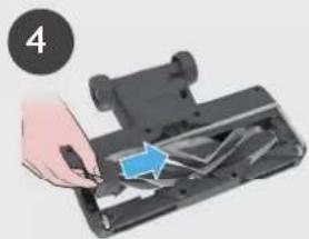
natural_image
Hand inserting a component into a device (no text or symbols visible)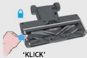
text_image
'KLICK'5. UNDERHÅLL AV DAMMSUGAREN
5.4MOTORISERATHUSDJURSVERKTYG
text_image
Exploded view diagram of a vacuum cleaner with labeled parts from B to O**2. LAITTEEN KOKOAMINEN
flowchart
graph LR
    A["1 2 3 4 5 6"] --> B["Chamber with power plug"]
    B --> C["Chamber connected to charging unit"]
    C --> D["Switch: ①"]
    D --> E["Device: 人头*"]
    E --> F["Device: +"]
    F --> G["Hand inserting battery into charging device"]
4. LAITTEEN KÄYTTÖ
natural_image
Three mechanical components with numbered labels (1, 2, 3) shown in separate views, no text or symbols present.natural_image
Three-panel image showing a robotic device with a close-up of the handle and a close-up of a bed mat on a rug, all without visible text or symbols.4.2 LATTIAN YLÄPUOLELLA -TILA / RIKKAIMURITILA
5.1PÖLYSÄILIÖNTYHJENNYS
natural_image
Illustration of hands installing or adjusting a mechanical component with numbered parts (no text or symbols visible)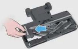
natural_image
Hand inserting a component into a device (no visible text or symbols)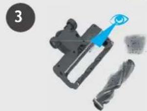
natural_image
Mechanical component with a blue tool interacting with a black saw blade (no text or symbols visible)
natural_image
Illustration of hands pouring liquid from a container into a metal container (no text or symbols)
natural_image
Hand inserting a component into a device (no text or symbols visible)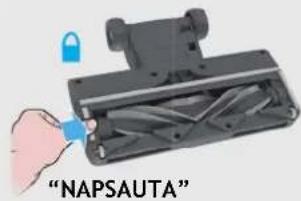
text_image
"NAPSAUTA"5. LAITTEEN KUNNOSSAPITO
5.4 MOOTTOROITU TYÖKALU KOTIELÄINTEN KARVOJEN POISTOON\*
text_image
Exploded view diagram of a vacuum cleaner with labeled parts from B to O**natural_image
Three mechanical components with numbered callouts, shown from different angles (no text or symbols present)4.1 XPHΣH STICK
natural_image
Two-panel image showing a robotic device with a close-up inset of the device's handle, alongside a photo of a baby washing machine on a patterned rug (no text or symbols visible)text_image
Exploded view diagram of a vacuum cleaner with labeled parts from B to O**flowchart
graph LR
    A["1 2 3 4 5 6"] --> B["Chamber with power plug"]
    B --> C["Power input switch"]
    C --> D["Digital display controller with battery and indicator lights"]
    D --> E["Control panel with '入火灯' (Electrician) and '充电按钮' (Battery)"]
    E --> F["Hand inserting battery to output"]
natural_image
Three mechanical components with numbered labels (1, 2, 3) showing different assembly states (no text or symbols on parts)4.1 РЕЖИМ С ТРУБКОЙ
natural_image
Two-panel image showing a robotic device with a close-up inset of the device's handle, and a photo of a baby washing machine on a patterned rug in a living room setting (no text or symbols visible)text_image
Diagram showing two steps of a device being inserted into a device, labeled with numbered instructions and blue arrows indicating the process.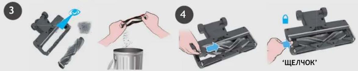
text_image
3 4 'ЩЕЛЧОК'text_image
Exploded view diagram of a vacuum cleaner with labeled parts from B to O**text_image
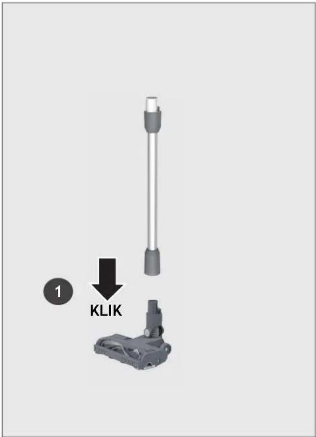
1 KLIKNIĘCIE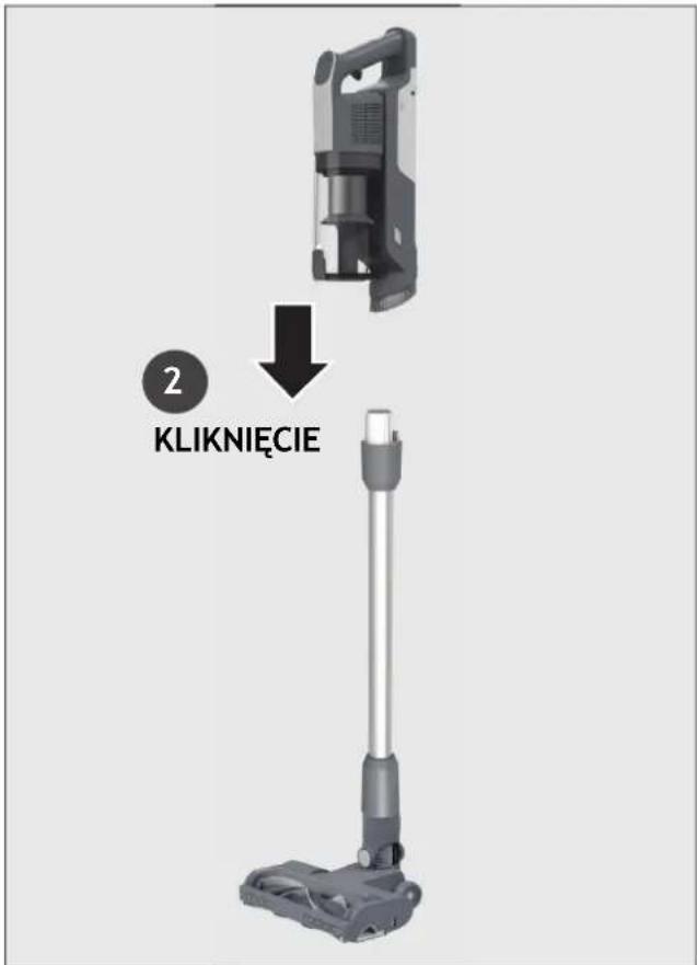
text_image
2 KLIKNIĘCIEtext_image
KLIKNIĘCIE KLIKNIĘCIE3. LADOWANIE AKUMULATORA
flowchart
graph LR
    A["12/3/4/5/6"] --> B["Device with cable"]
    B --> C["Device with plug"]
    C --> D["Device with switch"]
    D --> E["Device with battery"]
    E --> F["Device with hand action"]
    F --> G["Device with battery and hand action"]
text_image
1 2 3 4 5 6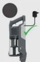
natural_image
Illustration of a handheld device with a circular component and a green checkmark (no text or symbols)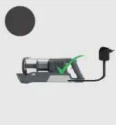
natural_image
Simple line drawing of a mechanical device with a green checkmark and black connector (no text or symbols)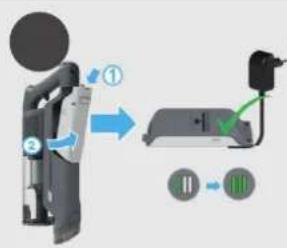
text_image
Diagram showing a device with labeled components and directional arrows, likely illustrating a system or process flow.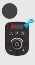

natural_image
Hand using a handheld device to adjust battery and switch (no text or symbols visible)4. KORZYSTANIE Z ODKURZACZA
natural_image
Three mechanical components with numbered labels (1, 2, 3) shown in separate views, no readable text or symbols present.flowchart
graph TD
    A["Step 1: Boot with hand press"] --> B["Step 2: On/OFF/ON icons"]
    B --> C["Step 3: Hand press with brake lever"]
    C --> D["Step 4: Triggerer with timer and buttons"]
    D --> E["Step 5: Display with 'TRYB ECO' and 'TRYB STANDARDOWY' indicators"]
    E --> F["Step 6: Display with 'TRYB TURBO' and 'TRYB TURBO' icons"]
4.1.1 TRYBELASTYCZNY \*
natural_image
Three-panel image showing a robotic device with a close-up inset of the device's handle, and a photo of a baby washing machine on a patterned rug in a cozy living room (no text or symbols visible)4.2 TRYB POWYŻEJ PODŁOGI / RĘCZNY
text_image
Diagram showing two-step installation of a mechanical device with labeled parts and directional arrows indicating motion.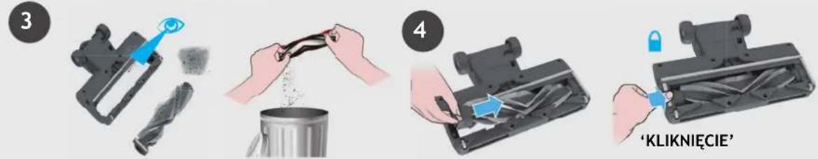
text_image
3 4 'KLIKNIĘCIE'5. KONSERWACJA URZĄDZENIA
5.4 ZMOTORYZOWANA SZCZOTKA DO SIERŚCI
text_image
Exploded view diagram of a vacuum cleaner with labeled parts from B to O**2. PŘÍPRAVA VYSAVAČE
flowchart
graph LR
    A["1 2 3 4 5 6"] --> B["Chamber with power plug"]
    B --> C["Chamber connected to charging unit"]
    C --> D["Switch: ①"]
    D --> E["Device: 人头*"]
    E --> F["Device: +"]
    F --> G["Hand inserting battery into charging device"]
4. JAK POUŽÍVAT VYSAVAČ
natural_image
Three mechanical components with numbered callouts, shown from different angles (no text or symbols on parts)4.1 STANDARDNÍ REŽIM
CZ
natural_image
Three-panel image showing a robotic device with a close-up inset of the device's handle, and a photo of a baby washing machine on a patterned rug in a living room setting.4.2 REŽIM POUŽITÍ SE ŠTĚRBINOVÝM NÁSTAVCEM / REŽIM RUČNÍ JEDNOTKY
text_image
ON REŽIM ECO STANDARDNI REŽIM REŽIM TURBO5. ÚDRŽBA VYSAVAČE
5.1 VYPRÁZDNĚNÍ NÁDOBY NA PRACH
text_image
Exploded view diagram of a vacuum cleaner with labeled parts from B to O**2. PRIPRAVA VAŠEGA SESALNIKA
Odstranite vse dele izdelka iz embalaže in sestavite svoj sesalnik.
- KORAK: Cev namestite na nastavek za tla.
text_image
1 KLIKtext_image
Diagram illustrating the installation of a KLIK vacuum cleaner with its internal components and assembly process.3. POLNJENJE BATERIJE
natural_image
Three mechanical components with numbered callouts, shown from different angles (no text or symbols on parts)4.1 STANDARDNI NAČIN (STICK MODE)
SI
flowchart
graph TD
    A["Step 1: Boot with hand press"] --> B["Step 2: ON OFF"]
    B --> C["Step 3: Hand press with brake"]
    C --> D["Step 4: EKO Način (80% on hand press)"]
    D --> E["Step 5: Standard Način (80% on hand press)"]
    E --> F["Step 6: Turbo Način (80% on hand press)"]
    F --> G["End"]
4.1.1 PRILAGODLJIV NAČIN\*
natural_image
Three-panel image showing a robotic device with a close-up inset of the device's handle, and a close-up of a baby toy on a bed mat (no text or symbols visible)4.2 NAČIN NAD TLEMI / ROČNI NAČIN
text_image
Exploded view diagram of a vacuum cleaner with labeled parts from B to O**2. SÜPÜRGENİZİN HAZIRLANMASI
text_image
Diagram illustrating the installation of a vacuum cleaner with TIK (Time-Kilk) components, showing assembly and cleaning steps.3. PILIN DEĞİŞTIRILMESI
flowchart
graph LR
    A["1 2 3 4 5 6"] --> B["Chamber with power plug"]
    B --> C["Chamber connected to charging unit"]
    C --> D["Switch: ①"]
    D --> E["Device: 人头*"]
    E --> F["Device: +"]
    F --> G["Hand inserting battery into charging device"]
4. TEMİZLEYİCİNİN KULLANIMI
natural_image
Three black-and-white diagrams showing mechanical components with no visible text or symbols4.1 DİK MOD
TR
flowchart
graph TD
    A["1: Foot Step"] --> B["2: ON Icon"]
    B --> C["3: Hand press"]
    C --> D["4: Display with EKO MODU, STANDART MOD TURBO MODU"]
    D --> E["5: Display with X1/2 indicators"]
4.1.1ESNEKMOD \*
natural_image
Three-panel image showing a robotic device with a close-up inset of the device's handle, and a photo of a baby washing machine on a patterned rug in a cozy living room (no text or symbols visible)4.2 ZEMİN ÜSTÜ MOD / EL ÜNİTESİ MODU
flowchart
graph TD
    A["Device is being inserted into a container with an eye icon"] --> B["Add X 5"]
    B --> C["Check the device for 'OFF'"]
    C --> D["Close the device with 'ITIN'"]
    D --> E["Adjust internal components with 'KLİK'"]
    E --> F["Final assembly with 'KLİK'"]
text_image
Illustration showing hands installing components of a device with numbered labels ① and ② indicating different parts or functions.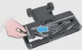
natural_image
Hand inserting a component into a device casing (no visible text or symbols)3
natural_image
Close-up of a mechanical device with a blue eye icon pointing to it, alongside two metallic blades (no text or symbols visible)
natural_image
Illustration of hands pouring liquid from a container into a metal container (no text or symbols)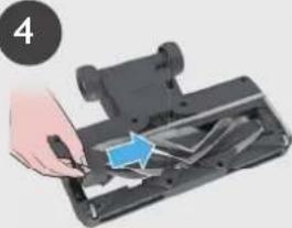
natural_image
Hand inserting a component into a device (no text or symbols visible)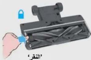
text_image
"النقر"- صيانة جهاز التنظيف
The image is too blurry to recognize any text content.
natural_image
Illustration of a hand using a hairdryer to cut a black fabric with scissors, and then to spread spools (no text or symbols)The image contains no text or characters. Therefore, the correct OCR output is an empty string.
text_image
Diagram showing a hand operating a mechanical device with labeled parts ① and ②, indicating a step in operation.text_image
Diagram illustrating a mechanical assembly process with numbered steps and labeled componentsflowchart
graph TD
    A["Step 1: Hand press on seat"] --> B["Step 2: ON/OFF state"]
    B --> C["Step 3: Handle press on seat"]
    C --> D["Step 4: Handle press on seat"]
    D --> E["Action: 100% zoom, 100% zoom, 100% zoom, 100% zoom"]
    E --> F["Action: 100% zoom, 100% zoom, 100% zoom"]
    F --> G["Action: 100% zoom, 100% zoom, 100% zoom"]
    G --> H["Action: 100% zoom, 100% zoom, 100% zoom"]
natural_image
Two-panel image showing a remote-controlled device with blue control panel and a close-up of a baby vacuum cleaner in a living room setting (no text or symbols visible)natural_image
Three mechanical devices with black components, shown from different angles (no text or symbols visible)text_image
Diagram illustrating the installation of a vacuum cleaner with labeled components and airflow direction.مكونات المنتج:
text_image
I* H J K*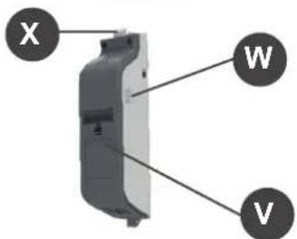
text_image
X W V
natural_image
Simple diagram of a screwdriver with a labeled point Q (no text or symbols beyond the label)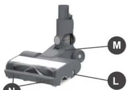
text_image
M N L