TISSEL200 - Pump Pedrollo - Free user manual and instructions
Find the device manual for free TISSEL200 Pedrollo in PDF.
User questions about TISSEL200 Pedrollo
0 question about this device. Answer the ones you know or ask your own.
Ask a new question about this device
Download the instructions for your Pump in PDF format for free! Find your manual TISSEL200 - Pedrollo and take your electronic device back in hand. On this page are published all the documents necessary for the use of your device. TISSEL200 by Pedrollo.
USER MANUAL TISSEL200 Pedrollo
cod 12039901TS2 05/21
IT ISTRUZIONI ORIGINALI PER L'USO ITALIANO EN ORIGINAL INSTRUCTIONS FOR USE ENGLISH ES INSTRUCCIONES ORIGINALES DE USO ESPAÑOL
FR MODE D'EMPLOI ORIGINAL
natural_image
Two red industrial pumps with blue and silver casing, connected by cables (no visible text or symbols)MADE IN ITALY
TISSEL-200
IT ISTRUZIONI ORIGINALI PER L'USO 4
EN ORIGINAL INSTRUCTIONS FOR USE....26
ES INSTRUCCIONES ORIGINALES DE USO....48
FR MODE D'EMPLOI ORIGINAL....70
text_image
Labeled diagram of a mechanical device with numbered components for identification- N.O. NORMALY OPEN FLOW
- COMMON FLOW
5.0 V o GND FLOW
text_image
CE UK CA EACUK legislation: 2008 No. 1597, 2016 No. 1101, 2016 No. 1091, 2019 No. 539, 2012 No. 3032
San Bonifacio, 11/07/2018
Pedrollo S.p.A.
Il Presidente
Silvano Pedrollo

EN - ORIGINAL INSTRUCTIONS FOR USE
CONTENTS
GENERAL INFORMATION......27
SAFETY REGULATIONS......27
DESCRIPTION OF THE PRODUCT 28
LIST OF PARTS 28
DESCRIPTION OF CONTROL PANEL 28
LIMITATIONS OF USE 28
TECHNICAL DATA 29
POWER AND ABSORPTIONS 29
SELF-LIMITATION DUE TO OVERLOAD....29
ILLUMINATED SIGNS 29
INSTALLATION 30
MONITORING AND DISPLAY 31
POSITIONING OF THE PRODUCT....31
PRESSURE SENSOR 31
ELECTRICAL CONNECTIONS 32
WIRING AND CONNECTIONS....32
START UP 33
PRIMING OF THE PUMP 33
CONFIGURATION OF THE PARAMETERS 34
MODIFICATION OF THE PRESSURE OF THE SET 34
VISUALISATION OF THE FUNCTION PARAMETERS 34
VISUALISATION OF THE FIRMWARE VERSION (FW) 34
DEFINITION OF THE SWITCH OFF FREQUENCY 35
SETTING THE PARAMETERS IN THE HIDDEN LISTS 35
HIDDEN LISTS 35
MODIFICATION OF THE PARAMETERS BY USING THE KEYBOARD 36
SETTING THE BASIC PARAMETERS 38
SETTING THE ADVANCED PARAMETERS (ADV) 39
INSPECTION LIST (INSP) 41
TEST 41
CALIBRATION OF THE PRESSURE SENSOR....42
ALARMS 43
SEARCHING FOR FAILURES......44
DISPOSAL......46
DECLARATION OF CONFORMITY 46
GENERAL INFORMATION
This manual must always accompany this device and it must be kept in an accessible place so that the users and those responsible for its maintenance can consult it.
It is recommended that the installer/user should carefully read the specifications and the information contained in the present manual before using the product in order to avoid damage, the improper use of the equipment or the forfeiture of the guarantee.
This product must not be used by children or by persons with a reduced physical, sensory or mental capacity, or by those who lack experience or knowledge, if they have not received the necessary supervision and instruction. Care must be taken to avoid children playing with the device.
The manufacturer does not accept any responsibility in the event of accidents or damage caused by negligence or non-compliance with the instructions contained in this brochure or in conditions which differ from those set out below. Also it does not accept any responsibility for damage caused by the improper use of the pump.
Do not place any weights or other boxes on top of the package.
SAFETY REGULATIONS
In this manual symbols with the following meaning have been used:

This symbol warns that non-compliance with the specifications brings with it the risk of electric shocks.

This symbol warns that non-compliance with the specifications brings with it the risk of harm to persons or damage to property.
⚠️ Before installing and using the product:
- Carefully read this manual in all its parts.
- Installation and maintenance must be carried out by qualified personnel responsible for establishing the electrical connections in accordance with the existing rules and regulations.
- The manufacturer does not accept any responsibility for damage caused by maintenance or repairs carried out by unqualified personnel and /or by spare parts which are not original.
- The use of spare parts which are not original, tampering or misuse will result in the forfeiture of the guarantee.
During the initial installation and in case of maintenance make sure that:
- The power supply has been switched off
- The power supply is provided with safeguards and in particular a highly sensitive circuit breaker (30 mA in class A for domestic applications and in class B for industrial applications) and grounding in conformity with the rules.
- Before removing the lid of the inverter or starting procedures on it the power supply must be disconnected before waiting at least five minutes so that the capacitors have the time to lose their charge through the incorporated discharge resistors.
- Do not remove the board cover and/or disconnect the electricity to the pump if the inverter is in operation.
- WARNING: when the TISSEL-200 is out of service (red LED flashing) it is still electrically charged. Before any form of intervention on the pump or on the inverter it is obligatory to disconnect the power supply to the pump.
Emergency Stop
Whilst the TISSEL-200 is in operation it is possible to carry out an emergency stop by pressing the OFF/ON switch.
DESCRIPTION OF THE PRODUCT
TISSEL-200 is a speed regulator with the following characteristics.
- Input is a single-phase alternating voltage.
• Supplies a three-phase alternating voltage. - Keeps the pressure of the installation constant (curves with variable revolutions).
- Controls the hydraulic and electrical operating parameters, and protects the pump from faults.
- It can be fitted with an expansion card which enables it to work in parallel with other inverters in the pump units and to manage an input signal and an output signal.
- It adapts to function with any type of pressurisation plant including current ones.
- It is energy saving as it limits the start-up and operating electric current.
- Allows the selection of the supply and output voltage.
LIST OF PARTS
- Inverter
- Pump
- Control Panel
- Cable seal
- Power card cover
- Technical data plate
text_image
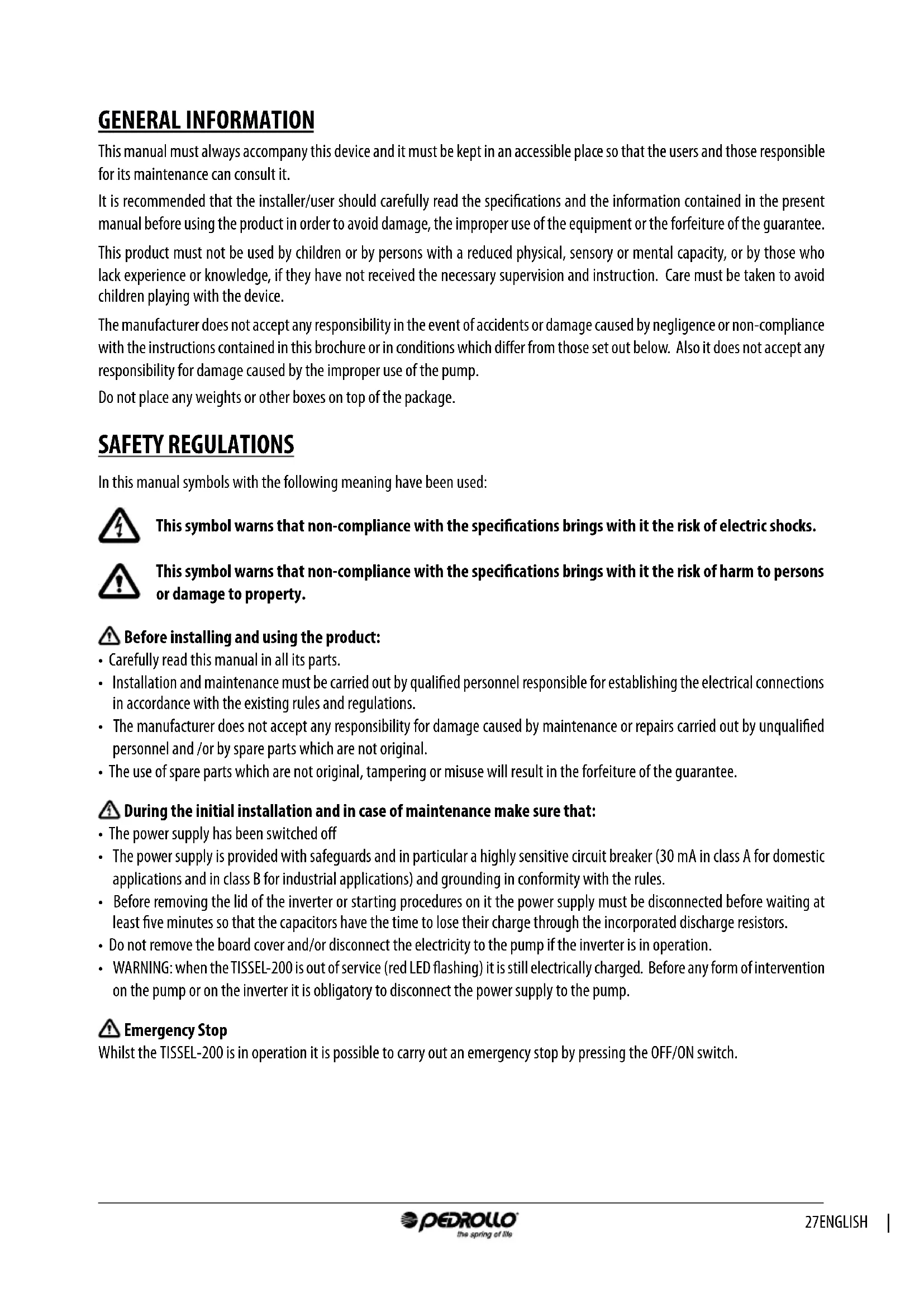
Labeled diagram of a mechanical device with numbered components for identificationDESCRIPTION OF CONTROL PANEL
1.0N/OFF switch
2. LED - red when POWER on
3. LED – green when in operation STATUS
4. Display
5. SET key
6. Keys of the slider arrows

text_image
1 2 POWER 3 STATUS 4 PEDROLLO the spring of ria 5 ON OFF SET 6 ACE IP 8.5 TISSEL-200 INVERTERLIMITATIONS OF USE
• Maximum working pressure: 9 bar (130 p.s.i.).
- Permissible fluids: clean water and chemically non-aggressive liquids; if the liquids contain impurities install a filter upstream.
• Maximum ambient temperature: 40 °C, with the possibility of changing the air.
- Minimum ambient temperature: 0 °C
• Maximum temperature of the fluid: 50 °C
- Minimum temperature of the fluid: 0 °C
- Permitted variation in the supply voltage + / - 10% compared to the plate data.
- TISSEL-200 is not suitable for pumping inflammable liquids or for operating in areas where there is a danger of explosion.
TECHNICAL DATA
• Supply voltage: 230+/-10% V single phase
• Outlet voltage: 230 V three-phase
• Frequency: 50-60 Hz
• Level of protection: IP 65
• Vertical work position, with entrance of liquid from below and exit from above.
ATTENTION: in the presence of a low voltage (nominal value -10%) there may be power surges at the start and at maximum power
POWER AND ABSORPTIONS
Model V in V out A out P2 max (kW) P2 max (HP)
TISSEL-200 (7 A) 1 \~ 230 V 3 \~ 230 V 7 1.1 1.5
TISSEL-200 (12 A) 1 \~ 230 V 3 \~ 230 V 12 2.2 3.0
SELF-LIMITATION DUE TO OVERLOAD
If the current recorded by the inverter or the temperature of the components of the inverter exceed the safety limits TISSEL-200 starts a progressive reduction in the frequency of operation until the values exceeding the limits return to normal.
ILLUMINATED SIGNS
| ONOFFFLASHING | POWER ○ STATUS ○ | TISSEL-200 does not detect a power supply.ATTENTION: the absence of a power supply is not guaranteed, the card could be damaged but still live. |
| POWER ○ STATUS ○ | TISSEL-200 is live but the pump is not running (STAND-BY) | |
| POWER ○ STATUS ○ | TISSEL-200 is live and the pump is running | |
| POWER ○ STATUS ○ | TISSEL-200 is live but OUT OF SERVICE (or in TEST), restoration is only manual | |
| POWER ○ STATUS ○ | TISSEL-200 is in a state of alarm, restoration is only manual |
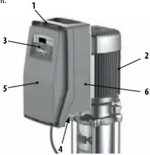
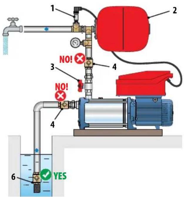
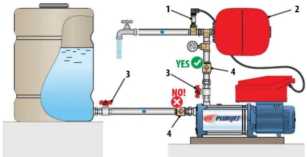
INSTALLATION
TS2-PLURIJET
text_image
1 2 3 4 YES ✓ NO! PLURIJET 4 5 NO!TS2-MK TS2-CR TS2-FCR
text_image
1 2 3 4 NO! NO! 4 6 YESTS2-PLURIJET TS2-MK TS2-CR
text_image
1 2 3 YES ✓ NO! PLURJETLIST OF COMPONENTS
- Pressure Sensor
- Expansion Tank
- ON-OFF valve
- Check valve
- Suction filter
- Foot valves with suction filter
MONITORING AND DISPLAY

During both the first installation and maintenance ensure THERE IS NO POWER in the line

During both the first installation and maintenance ensure the plant is UNPRESSURED

DO NOT OPEN THE COVERS OF THE INVERTER
In addition ensure that the electricity supply has protections and in particular has a differential switch of great sensitivity (30 mA in class A for domestic applications and in class B for industrial applications) and grounding in conformity with the regulations.
Verify that the data on the plate are those desired and that they are adequate for the installation.
Install TISSEL-200 in a place:
– protected from external agents
- ventilated, free of excess humidity or too much dust
— where it does not suffer from harmful vibrations or mechanical stresses from the tubes connected to it.
POSITIONING OF THE PRODUCT
- Fix the unit with screws onto a solid horizontal base.
- If the pump has to be installed externally where it might freeze protect it to avoid freezing.
IMPORTANT
For the correct functioning of the TISSEL-200 the installation of an adequate expansion tank is absolutely necessary.
- The expansion tank:
— Accumulates water under pressure in order to reduce to a minimum the start of the pumps. - It is indispensable in the presence of small losses of the installation.
- It absorbs eventual over-pressures coming from the plant.
– The minimum volume required in litres (for models with a membrane) is indicatively equal to 10% of the maximum flow rate of a single pump, expressed in l/min.
Example of a standard application: Q_max = 80 l/min V = 80 × 10% = 8 litres (rounded up by excess to the commercial size)
- Pre-load pressure (with an empty plant): approximately 70% of the work pressure:
Example: Pset = 4 bar → Pre-load pressure = 4 x 70% = 2.8 bar
- Correctly connect the supplied pressure sensor to the installation (see next chapter).
PRESSURE SENSOR
A pressure sensor is a transducer which measures the pressure of a liquid or a gas by means of an electrical signal sent to a receiver in analogue format. Pressure sensors are therefore also called pressure transducers.
The operating principle is based on the physical deformation of the strain gauge filament present in the membrane of the transducer: the electrical resistance is proportional to the applied pressure, which is converted into an electrical signal, the exit is transmitted as a current which varies from 4 to 20 milliamps.
The pressure sensor should be indicatively positioned in the installation as shown in the drawings (see previous page)
ELECTRICAL CONNECTIONS
- The electric connections between the pump and the inverter are implemented in full in the factory and therefore for its functioning nothing needs to be done.
- TISSEL-200 is connected to the electricity supply (230 V/50 Hz) by means of an electric cable.
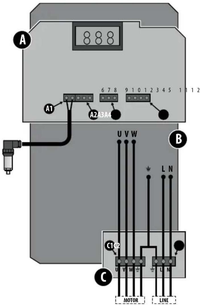
WIRING AND CONNECTIONS
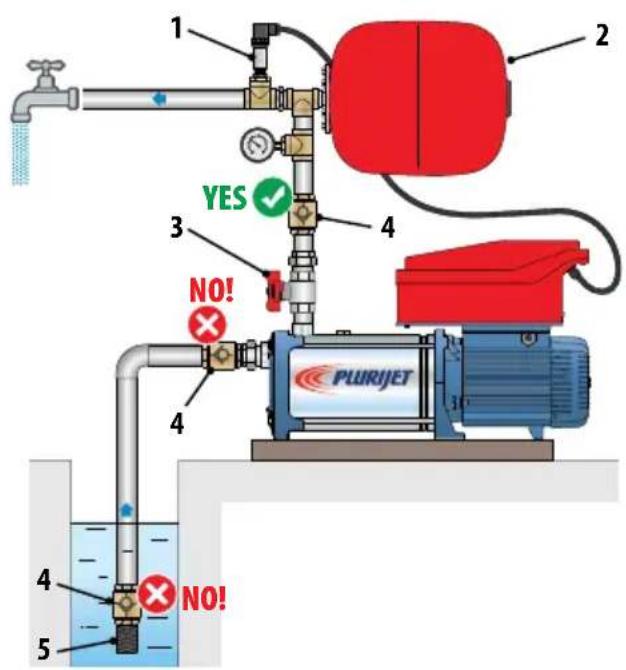
The inverter is made up of 3 cards
A) Control card
B) Power card
C) Feed and motor output card
In card A there are 4 connectors:
A1) 2 pin PRESSURE SENSOR connector
Description functions of the terminals:
- +Vdc (colour sensor cable: brown)
- 4÷20 mA (colour sensor cable: white)
A2) 3 pin FLOW SENSOR connector
Description functions of the terminals:
- N.O. NORMALY OPEN FLOW
- COMMON FLOW
5.0 V or GND FLOW
A3) 3 pin SERIAL CONNECTION connector
(Communication between inverters in parallel in the MASTER/SLAVE configuration)
Description functions of the terminals:
- RS 485 D+
- RS 485 D-
- RS 485 o GND
A4) 4 pin ENTRANCE/EXIT SIGNALS connector
(eg. level signal in entrance and alarm signal in exit)
Description functions of the terminals:
9.+Vdc
10. INPUT
11. COMMON OUTPUT
12. N.O. NORMALY OPEN FLOW OUTPUT
In card C there are 4 connectors:
C1) 4 pin MOTOR EXIT connector
C2) 3 pin SUPPLY connector
text_image
A A1 6 7 8 9 1 0 1 2 3 4 5 1 1 1 2 A2A3A4 B U V W ± L N C1C2 C U V W ± L N MOTOR LINESTART UP
PRIMING OF THE PUMP
- Before switching on read the attached manual and follow the instructions, in order to avoid errors in settings and operations which could cause anomalies in functioning.
- Do not switch on the pump when it is dry, not even for a few seconds.
- Before switching on the pump, prime the pump.
- Insert the plug in the socket.
- Press the switch (1) and wait for it to START (about 10 seconds).
- After 10 seconds the STARTING phase ends and TISSEL-200 returns to the same operating conditions which it was in when it was last switched off:
— IN SERVICE if when it was last switched off it was IN SERVICE. - OUT OF SERVICE if when it was last switched off it was OUT OF SERVICE (OFF).
In the case of an accidental fall in power, if TISSEL-200 was IN SERVICE (ON), when the power returns it will automatically return to IN SERVICE (ON). - To put TISSEL-200 in service press the key (2) ON/OFF on the control panel.
• TISSEL-200 starts to function. - If the pump is not correctly primed place Tissel-200 into the TEST mode (manual control) and gradually open the delivery valve (for its functioning in TEST mode see the respective chapter later in this manual).
ATTENTION: the inverter is perfectly configured in accordance with the predefined factory settings, in order to function correctly with the associated pump.
If it were necessary to modify the factory settings of the TISSEL-200 set the inverter using the parameters in the HIDDEN LIST (see chapter SETTING UP PARAMETERS IN THE HIDDEN LISTS).
MODIFICATION OF THE PRESSURE OF THE SET
| To increase by 0.1 bar press both the keys at the same time |  |  |
| To decrease by 0.1 bar press both the keys at the same time |  |  |
VISUALISATION OF THE FUNCTION PARAMETERS
- To visualise the parameters on the display whilst it is functioning scroll with the keys

- By pressing the key

one returns to the visualisation of the pressure of the system on the display.
DISPLAY DESCRIPTION U.M.
| P 3.2 | SYSTEM PRESSUREMeasured pressure of the system | bar |
| F 45 | WORK FREQUENCYImmediate frequency of operation of the motor | Hz |
| A 6.5 | ABSORBED CURRENTImmediate current absorbed by the motor – ATTENTION: RMS value:the reading of the electric current entering and exiting from the inverter, registered by normal measuring instruments (eg. amperometric clamp), could be incorrect. | A |
| Tm 50 | TEMPERATURE OF POWER MODULETemperature of the electronic power module of the inverter | °C |
VISUALISATION OF THE FIRMWARE VERSION (FW)
In order to visualise the FIRMWARE (FW) version of the INTERFACE (FWI) card and the POWER (FWP) card:
• Take the TISSEL-200 OUT OF SERVICE (OFF) by pressing the OFF ON key
- Press both the keys at the same time


DEFINITION OF THE SWITCH OFF FREQUENCY
(only possible in the AUTOMATIC FUNCTION mode)
- The switch off frequency is a defined minimum frequency threshold and as long as the functional frequency is above this threshold (namely there will be a demand for water) the inverter will keep the pump switched on. When the frequency of operation falls below this threshold (namely there will no longer by a demand for water) the inverter stops the pump.
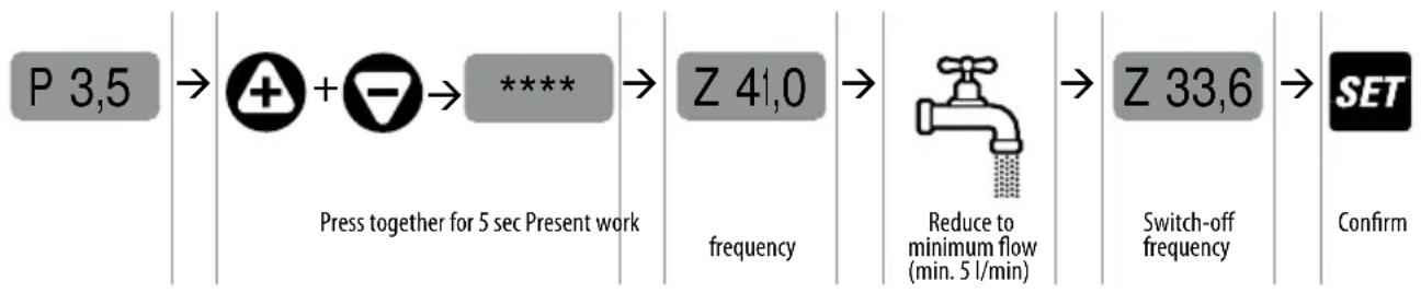
flowchart
graph LR
    A["P 3,5"] --> B["Press together for 5 sec Present work"]
    B --> C["Z 41,0 frequency"]
    C --> D["Reduce to minimum flow (min. 5 l/min)"]
    D --> E["Z 33,6 Switch-off frequency"]
    E --> F["Confirm"]
SETTING THE PARAMETERS IN THE HIDDEN LISTS
In order to enter into the Hidden Lists where there are the advanced parameters and if it were necessary to modify the factory values of these same parameters proceed as follows.
• Take the TISSEL-200 OUT OF SERVICE (OFF) by pressing the OFF ON key
- Press both the keys at the same time + + - SET
HIDDEN LISTS
| BASIC | BASIC LIST Parameters | These are BASIC PARAMETERS which have to be set depending on the application. |
| ADV | ADVANCED LIST Parameters | These are the ADVANCED PARAMETERS which improve the functioning and which require a detailed knowledge of the system. |
| INSP | INSPECTION LIST Parameters | These are the INSPECTION PARAMETERS which enable the user to inspect the operational status of the system, visualising hours of work, number of starts, history of the alarms, etc. |
| TEST | TEST Mode (accessible only in the OFF mode) | The TEST mode allows one to start and stop the pump manually (ON/OFF key) and modify the frequency by 1 Hz at a time. It also allows one to control the functional parameters of the motor and of the inverter.ATTENTION: when functioning manually some of the automatic controls are excluded and the operator must avoid any wrong manoeuvres. |
MODIFICATION OF THE PARAMETERS BY USING THE KEYBOARD
To SCROLL the parameters of the HIDDEN LISTS use the switches


To ENTER and EXIT from the parameters use the switches


To MODIFY the parameters use the switches


STRUCTURE OF THE LIST
BASIC
P SET PRESSURE
SS FULL-SCALE PRESSURE SENSOR
A CURRENT TO THE MOTOR
OF SWITCH OFF FREQUENCY
RO ROTATION OF THE MOTOR (only models M/T)
ADV (ADVANCED)
d DIFFERENTIATED RESTART PRESSURE
PD MINIMUM WORK PRESSURE (%- I - dry)
W ADDRESS OF INVERTER
RF SPEED OF REACTION OF INVERTER
TF DELAY DUE TO NO FLOW STOP
Td DELAY DUE TO OPERATING DRY STOP
TP INTERNAL OF RESTARTING FOR DRY FUNCTIONING
EI INCOMING SIGNAL
EO EXIT SIGNAL
It is imperative the BASIC PARAMETERS for the configuration of the inverter are set during the installation.
BASIC
| DISPLAY PARAMETERS DESCRIPTION | u.m. Default Min Max Step | ||||||
| P 3,5 | SET PRESSURE Sets the value of the pressure in the system (constant) | bar 3.5 1 9 0.1 | |||||
| psi 50 15 130 1.5 | |||||||
| SS 16 | FULL-SCALE OF PRESSURE SENSOR | Sets the full-scale of the pressure sensor: 10-16-25-40 bar | bar 16 10 40 | - | |||
| A 6,0 | MOTOR CURRENT Sets the nominal current of the motor on exit from the inverter (current of the motor - see name plate) | A | v.mod. | v.mod. | v.mod. | 0.1 | |
| OF 40 | FREQUENCY OF ARREST DUE TO LOW FLOW | Sets the frequency below which it is considered that the flow is less than the minimum flow requirements | Hz 40 25 60 | 1 | |||
| RO→ | DIRECTION OF ROTATION OF THE MOTOR | Sets the direction of rotation of the THREE-PHASE motor (clockwise or anti-clockwise) | - | - | - | - | - |
SETTING THE ADVANCED PARAMETERS (ADV)
The following is the list of the ADVANCED PARAMETERS which improve the functioning and which require a detailed knowledge of the system
ADV
| DISPLAY PARAMETERS DESCRIPTION | u.m. Default Min Max Step | ||||||
| d 0.4 | DIFFERENTIAL RESTART PRESSURE | Sets the differential between the pressure selected (SET PRESSURE) and the effective restart pressure. | bar 0.4 0.4 1.0 0.1 | ||||
| psi 6 6 15 1.5 | |||||||
| Pd 50 | iDRY PRESSURE | Sets the value of the minimum pressure (expressed as the % of the SET pressure) which must be reached in order to avoid activating a dry running alarm. Setting the value at 0% excludes the intervention due to dry running because of a minimum pressure. | % 10 0 | 100 | 1 | ||
| W NC | TASK OF INVERTER | Defines the task of each inverter unit: (STAND ALONE/MASTER/SLAVE). | - | NC | NC/ MS/ S1/ S2 | ||
| RF 3 | RAPIDITY OF INVERTER REACTION | Sets the rapidity of response of the inverter to changes in pressure. | - | 3 | 1 | 5 | 1 |
| TF 7 | DELAYED STOP DUE TO NO FLOW | Setting the value to "0" one excludes automatic attempts to restart. | sec | 7 1 15 1 | |||
| Td 10 | DELAYED STOP DUE TO DRY RUNNING | Sets the delayed stop of the pump in conditions of dry running. | sec | 10 1 | 100 | 1 | |
| TP 10 | RESTART INTERVALS DUE TO DRY RUNNING | Sets the interval between two successive automatic attempts to restart after a stop due to dry running.Setting the value at "0" one excludes automatic attempts to restart. | min 10 0 | 100 | 1 | ||
| EI 1 | ENTRANCE SIGNAL | Sets the FUNCTION of the incoming signal, of the clean contact type; closing the contact activates the function. | - | 1 | 0 | 5 | 1 |
| EI = 0: no function, the state of the entrance is ignoredEI = 1: entrance level signalEI = 2: start and stop by external signalEI = 3. Passage to the 2nd SETPOINT of pressureEI = 4: entrance external flow signalEI = 5. Entrance alarm reset signal | |||||||
| EO 1 | EXIT SIGNAL | Sets the FUNCTION of the exit signal, of the clean contact type, with NO logic. | - | 1 | 0 | 3 | 1 |
| EO = 0: no function; the relay is not activatedEO = 1: alarm sounds; the relay is activated if the inverter alarm is set offEO = 2: pump switched on: the relay is activated if the pump is switched onEO = 3: recycling function; activates the exit relay at time intervals defined by the Al parameterparametro AI.Max 0,5 A @ 240 VacMax 0,5 A @ 30 Vdc | |||||||
| LF 30 | MINIMUM FREQUENCY | Sets the minimum operating frequency | Hz | 30 | 25 | 40 1 | |
Follows
| DISPLAY PARAMETERS DESCRIPTION | u.m. Default Min Max Step | |||||
| HF 50 | MAXIMUM FREQUENCY | Sets the maximum operating frequency.ATTENTION: the increase in the maximum frequency.compared to the nominal frequency can cause strong overloads of the motor. | Hz MF | MF-10 | MF+5 | 1 |
| FS 8 | SWITCHING FREQUENCY OF MODULE | Sets the switching frequency of the power module.kHz 84102 | ||||
| LP 0,2 | LOW PRESSURE ALARM THRESHOLD | Sets the alarm threshold for too low an operating pressure (possibility of a broken tube). | bar 0,20100,1 | |||
| FWS 0 | FLOW SENSOR | Sets the presence/absence of the flow sensor:0 = sensor not present.1 = flow sensor present. | -0 | 0 | 1 | 1 |
| 2P 2.5 | SECOND PRESSURE OF SET | Sets a second value for the system pressure (constant). To activate it configure the parameter EI in the advanced parameters. | bar 2,5190,1 | |||
| psi 50 | 15 | 1301,5 | ||||
| SET.F | RESETTING OF FACTORY PARAMETERS | Press the ENTER key until “OK” appears on the display, all the parameters return to their factory settings. | ||||
INSPECTION LIST (INSP)
The INSP (Inspection) list allows one to visualise the history of functioning of the inverter, in particular the hours of functioning, the number of start times, the registration of the alarms.
| INSP | WH | HOURS OF FUNCTIONING OF THE PUMP | Hours of functioning of the pump (motor switched on. |
| TH | HOURS INVERTER SWITCHED ON | Hours of functioning (device switched on, with pump functioning or in STAND-BY). | |
| NS | TOTAL NUMBER OF STARTS | Number of starts of the pump, from the time of installation. | |
| SH | AVERAGE NUMBER OF STARTS | Average number of starts each hour the inverter is switched on. | |
| E1 | LAST ERROR Last error registered. | ||
| EH | HOUR OF LAST ERROR Hour last error registered (referred to TH). | ||
| EE | ZEROING ERRORS Allows one to reset the errors register; to reset the register press the SET button and keep it pressed until “OK” appears on the display.(SET → ***** → OK) | ||
TEST
To switch on and regulate the pump manually:
- Enter into TEST mode through access to the HIDDEN LISTS.
- Proceed as shown below to start up and adjust the speed of the pump.
- During the TEST it is possible to display all the operating parameters (through the display of the operating parameters).
| INSTRUCTION | DISPLAY | |
| TEST mode (the word TEST appears on the display) | TEST | |
| Switch on the pump by pressing the OFF/ON switch; the pump starts up at the minimum frequency |  | P 2.0 |
| Display the operating frequency by scrolling with the arrow |  | F 30 |
| Vary the operating frequency by 1 Hz at a time with the arrows |  | F 35 |
| Display the operating parameters with the arrows |  | A 3.5 |
| At the end of the TEST switch off the pump by pressing the OFF/ON switch |  | OFF |
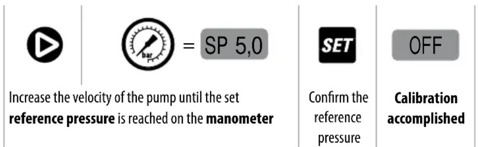
CALIBRATION OF THE PRESSURE SENSOR
In order to calibrate the pressure sensor the following must be supplied:
• A value of ZERO (system at zero pressure).
• A reference value (eg. system at 5 bar).
It is necessary to have:
- An auxiliary manometer on the same mandate circuit of the inverter.
- Set the pomp in action (open a tap).
To access the calibration, starting with the INVERTER in STAND-BY
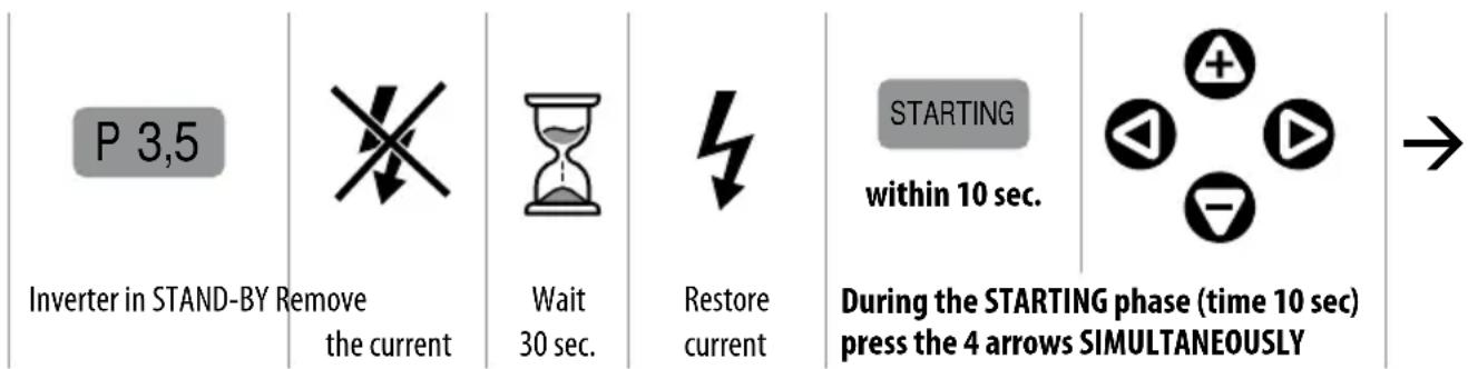
text_image
P 3,5 Inverter in STAND-BY Remove the current Wait 30 sec. Restore current STARTING within 10 sec. During the STARTING phase (time 10 sec) press the 4 arrows SIMULTANEOUSLY →Calibration
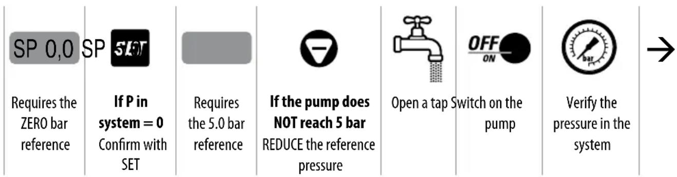
flowchart
graph LR
    A["SP 0,0"] --> B["If P in system = 0 Confirm with SET"]
    B --> C["Requires the 5.0 bar reference"]
    C --> D["If the pump does NOT reach 5 bar REDUCE the reference pressure"]
    D --> E["Open a tap Switch on the pump"]
    E --> F["Verify the pressure in the system"]
text_image
Increase the velocity of the pump until the set reference pressure is reached on the manometer = SP 5,0 Confirm the reference pressure OFF Calibration accomplishedALARMS
| OVER CURRENT | Alarm due to overcurrent greater than the planned tolerance. The inverter stops the pump; the reset is only manual. |
| CURRENT LIMIT | Alarm due to overcurrent greater than the capacity of the module The inverter stops the pump the reset is only manual. |
| DRY RUNNING | It arises if the pump is unable to reach the pre-set percentage of the set pressure, expressed by the parameter Pd (see Chapter SETTING OF THE ADVANCED PARAMETERS); the inverter stops the pump. The error is zeroed after the TP time (see chapter SETTING OF THE ADVANCED PARAMETERS). |
| DRY RUNNING PF | It arises if the electrical parameter COSFI falls to the value which indicates the dry running of the motor. The inverter stops the pump. The error is zeroed after the TP time (see chapter SETTING OF THE ADVANCED PARAMETERS). |
| P ERROR | It arises if the control card does not receive the signal from the pressure sensor. The error is automatically cancelled on receipt of the signal. |
| LOW PRESS It arises if the pump is rotating at maximum frequency in the presence of a flow, and the pressure does not reach the value of the parameter LP (see chapter SETTING OF THE ADVANCED PARAMETERS - default 0.2 bar); the inverter stops the pump. The error is overcome after the TP time (see chapter SETTING OF THE ADVANCED PARAMETERS). | |
| LOW VOLTAGE | A drop in voltage has been registered (even very briefly) which exceeds the functional tolerance (-15%); the inverter stops the pump; the error is overcome after one minute and the inverter restarts automatically. |
| HIGH VOLTAGE | A surge in voltage (even very briefly) which exceeds the functional tolerance (+15%) has been registered; the inverter stops the pump; the error is overcome after one minute and the inverter restarts automatically. |
| OVER TEMP. | The temperature of the module of the inverter has reached the critical threshold. The inverter stops the pump, the error is overcome when the temperature falls below 70°C and the inverter restarts automatically. |
| COM ERROR | There has been an error in the internal communications; if the error persists the electronic cards could be damaged. |
| LOW LEVEL | It arises when the digital entrance EI is configured as a signal of the level (EI = 1 - see chapter SETTING OF THE ADVANCED PARAMETERS), and the signal is not present. When the signal returns the message disappears and the inverter returns to function normally. |
| EXT OFF | This arises when the digital entrance EI is configured as being activated by an external order (EI = 2 - see chapter SETTING OF THE ADVANCED PARAMETERS), and the signal is not present. When the signal is again present (external restoration) the message disappears and the inverter returns to function normally. |
SEARCHING FOR FAILURES
- Verify that the inverter has been correctly attached to the electric cable
- Verify that the pump has been correctly attached to the inverter
- Verify that all the cables and connections are working.
| PROBLEM The pump does not switch on | ||
| Message Cause Intervention | ||
| None Interruption of the electricity supply Restore the electricity supply | ||
| None Blown fuses Replace the fuses | ||
| None Intervention of line protections Verify the correct calibration of the protection | ||
| INPUT ERROR (only models 1/1) – The connections LINE and MOTOR have been inverted | Verify the LINE and MOTOR connections and reconnect correctly | |
| PROBLEM Intervention of the differential switch to protect the power line of the inverter | ||
| Message Cause Intervention | ||
| None The differential switch is inadequate to supply the the inverter | Substitute the differential switch with a suitable direct current type for the components of the switches (Class A) | |
| PROBLEM The pump does not switch on | ||
| Message Cause Intervention | ||
| OFF The pump is out of service (switched off manually) | Put the pump back in service pressing the ON/OFF switch | |
| PROBLEM The pump has stopped and does not restart | ||
| Message Cause Intervention | ||
| OVER CURRENT Excess absorption of current compared to the set value (parameter A in BASIC PARAMETERS) | - Check the correct setting of the current- Check that the voltage under load is never too low (min - 15%)- That the pump turns freely- That the rotation is in the right direction- That the cables are of the right size | |
| CURRENT LIMIT Serious excess of absorption of current that exceeds the capacity of the inverter module | - Check that the pump is not blocked- Reduce the acceleration of the motor (factory parameter) | |
| DRY RUNNING (DRY RUNNING PF) | - No intake water- Pump not primed- Intake manifold obstructed- Reversed rotation of the motor | - Verify the presence of intake water- Switch on the pump- Check the intake manifold- Invert the sense of rotation of the pump motor |
| LOW PRESS The system does not reach the minimum pressure | Check there are no breakages in the tubes. | |
| LOW VOLTAGE Change in the voltage greater than -15% of the voltage on the plate | Stabilise the current to keep it in the ± 15% tolerance | |
| HIGH VOLTAGE | Change in the voltage greater than +15% of the voltage on the plate | Stabilise the current to keep it in the ± 15% tolerance |
| OVER TEMP MODULE | Increase in temperature not tolerated by the inverter module due to overload or excessive ambient temperature | - Verify that there are no accidental overloads- Improve the cooling of the surroundings |
| COM ERROR | The communication between the control card and the voltage card is suspended | If the message persists the electronic cards could be damaged |
| LOW LEVEL Signal of level | not present with EntrySignal of level activated | Verify the presence of water in suction or the functioning of the level signal |
| EXT OFF Put out of service | through an externalsignal with external Signal Entranceactive | Put back into service via the external signal |
| None Breakdown of the | pressure sensor Verify the reading on the | display with a reference manometer, re-programme or substitute the pressure sensor |
| PROBLEM Pump always functioning, even if not required | ||
| Message Cause Intervention | ||
| None Leaks in the plant greater than 2 l/min Find the leaks and block them | ||
| None Breakdown or obstruction of the loadsensor | Inspect and clean the load sensor | |
| PROBLEM The pump stops too soon, even if there is a demand | ||
| Message Cause Intervention | ||
| None Fault of the flow sensor sensor Verify the functioning of the flow sensor | ||
| PROBLEM Performance of the pump below that rated | ||
| Message Cause Intervention | ||
| None Presence of air in the intake manifold Clean out the intake manifold | ||
| None Pump obstructed or damaged Inspect the pump and eliminate the problem | ||
GUARANTEE
Before installing and using the product read all the parts of this manual carefully. The installation and the maintenance must be undertaken by qualified personnel responsible for the hydraulic and electrical attachments in accordance with the applicable current norms.
The manufacturer declines any responsibility for damages caused by an improper use of the product and is not responsible for damages caused by maintenance or repairs carried out by unqualified personnel and/or with non-original spare parts. The use of non-original spare parts, tampering with the product or improper use will result in forfeiture of the guarantee of the product which covers a period of 24 months from the date of purchase.
DISPOSAL
In order to dispose of the parts of which the cards of the TISSEL-200 are made you must respect the norms and the laws which are active in the countries where the group is being used.
Do not discard the polluting parts in the environment.
Correct disposal of WEEE (DIRECTIVE 2012/19/EU)
DECLARATION OF CONFORMITY

text_image
CE UK CA EACWe hereby declare under our exclusive responsibility, that the product in question results as being in conformity of what is requested by the following European Union Directives, including the latest changes, and by the relevant national laws of implementation.
2006/42/EU, 2014/35/EU, 2014/30/EU, 2009/125/EU, 547/2012/EU, 2011/65/EU, 2012/19/UE
UK legislation: 2008 No. 1597, 2016 No. 1101, 2016 No. 1091, 2019 No. 539, 2012 No. 3032
San Bonifacio, 11/07/2018
Pedrollo S.p.A.
Il Presidente
Silvano Pedrollo
text_image
Labeled diagram of a mechanical device with numbered components for identification- N.O. NORMALY OPEN FLOW
- COMMON FLOW
5.0 V o GND FLOW
PLACEMENT DU PRODUIT 75
CAPTEUR DE PRESSION 75
CONEXIONES ELÉCTRICAS....76
CÂBLAGES ET CONNEXIONS....76
DÉMARRAGE....77
AMORÇAGE DE LA POMPE....77
CONFIGURATION DES PARAMÈTRES 78
CHANGEMENT DE LA PRESSION DETARAGE....78
AFFICHAGE DES PARAMÈTRES DE FONCTIONNEMENT ....78
AFFICHAGE DE LA VERSION DU FIRMWARE (FW)....78
DÉFINITION DE LA FRÉQUENCE D'ARRÊT....79
RÉGLAGE DES PARAMÈTRES DANS LES MENUS CACHÉS....79
MENUS CACHÉS 79
CHANGEMENT DES PARAMÈTRES À L'AIDE DU CLAVIER....80
RÉGLAGE DES PARAMÈTRES DE BASE (BASIC) 82
RÉGLAGE DES PARAMÈTRES AVANCÉS (ADV)....83
MENU INSPECTION (INSP) 85
TEST 85
CALIBRAGE DU CAPTEUR DE PRESSION 86
ALARMES 87
RECHERCHE DES PANNES......88
GARANTIE 90
ÉLIMINATION 90
DÉCLARATION DE CONFORMITÉ....90
INFORMATIONS GÉNÉRALES
text_image
Labeled diagram of a mechanical device with numbered components for identificationDESCRIPTION DU PANNEAU DE COMMANDE
PLACEMENT DU PRODUIT
- N.O. NORMALY OPEN FLOW
- COMMON FLOW
5.0 V ou GND FLOW
DÉCLARATION DE CONFORMITÉ
CEEAC
- N.O. NORMALY OPEN FLOW
- COMMON FLOW
5.0 V или GND FLOW