Rob MR08Z - Lawn mower Zoef Robot - Free user manual and instructions
Find the device manual for free Rob MR08Z Zoef Robot in PDF.

User questions about Rob MR08Z Zoef Robot
0 question about this device. Answer the ones you know or ask your own.
Ask a new question about this device
Download the instructions for your Lawn mower in PDF format for free! Find your manual Rob MR08Z - Zoef Robot and take your electronic device back in hand. On this page are published all the documents necessary for the use of your device. Rob MR08Z by Zoef Robot.
USER MANUAL Rob MR08Z Zoef Robot
Rob

natural_image
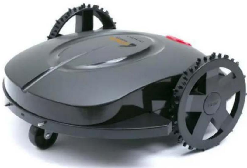
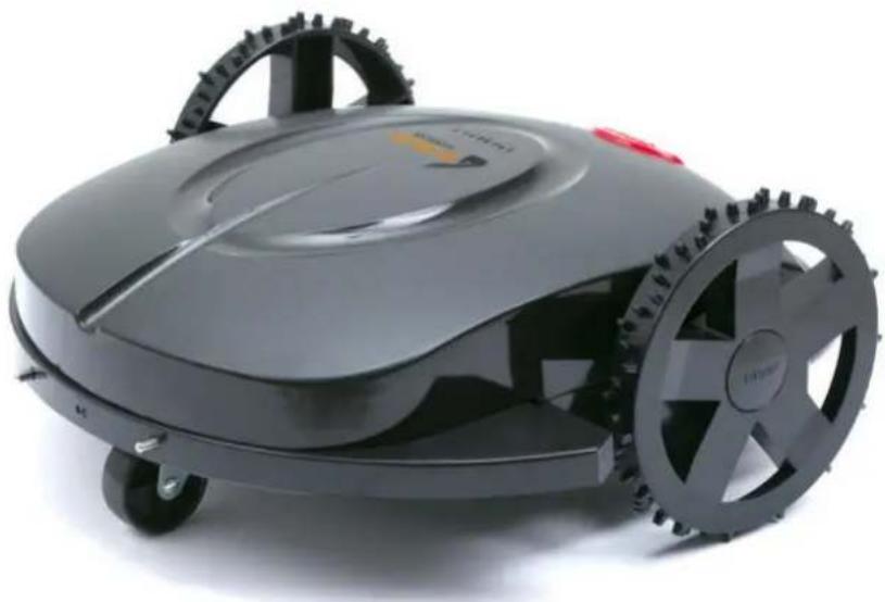
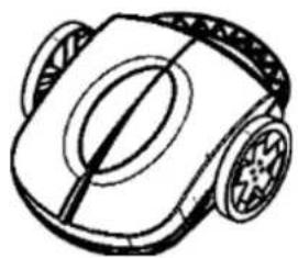
Black and white photo of a modern robotic lawn mower with visible wheels and head cover (no text or symbols)Robot Grasmaaier
MODEL MR08Z
Your Robot Brand
natural_image
Line drawing of a robotic vacuum cleaner (no text or symbols)Rob

natural_image
Line drawing of a mechanical device with no visible text or symbolsOplaad Station
Net Adapter
natural_image
Simple line drawing of two excavators on a slope with no text or symbols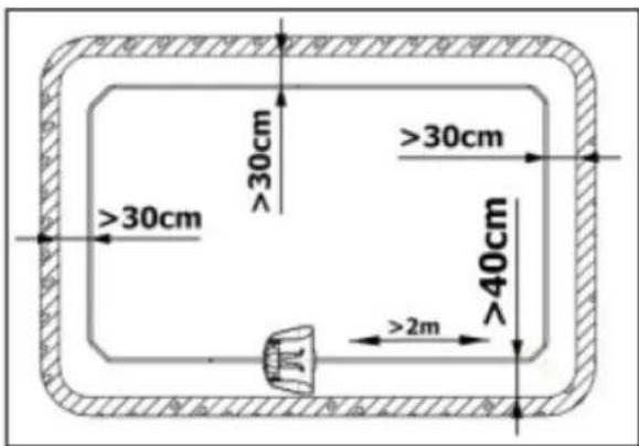
flowchart
graph TD
    A["Top Left"] --> B["Top Right"]
    B --> C["Bottom Left"]
    C --> D["Bottom Right"]
    D --> E["Bottom Left"]
    style A fill:#f9f,stroke:#333
    style B fill:#f9f,stroke:#333
    style C fill:#f9f,stroke:#333
    style D fill:#f9f,stroke:#333
    style E fill:#f9f,stroke:#333
natural_image
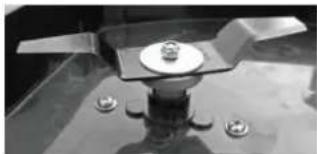
Close-up of a mechanical component with a central circular base and four small circular holes, no visible text or symbols.4 cm
natural_image
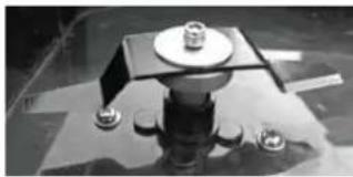
Close-up of a mechanical component with bolts and a central plate (no visible text or symbols)3 cm
natural_image
Close-up of a mechanical component with a central square base and two small protrusions (no visible text or symbols)5 cm
5. OPLADEN VOOR GEBRUIK:
natural_image
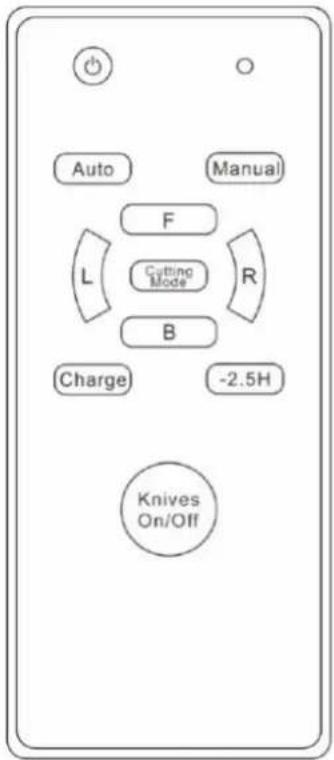
Technical line drawing of a mechanical component with arrows indicating motion or force direction (no text or symbols)MANUAL = Handmatige besturing
F = Vooruit (Forward)
B = Achteruit gaan (Back)
L = Linksaf
R = Rechtsaf
KNIVES = Messen Aan/Uit

Pauze (stop en start)
natural_image
Black-and-white photo of a small robotic lawn mower on grass, no visible text or symbolsYour Robot Brand
www.zoefrobot.nl

Rob
natural_image
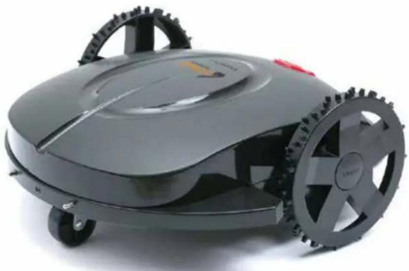
Black robotic lawn mower with visible wheels and a red handle (no text or symbols)Rasenmähroboter
MODELL MR08Z
Your Robot Brand
natural_image
Line drawing of a robotic vacuum cleaner (no text or symbols)Rob
natural_image
Line drawing of a mechanical component or housing with no visible text or symbolsLadestation
Netzadapter
natural_image
Simple line drawing of two excavators on a slope with no text or symbolsnatural_image
Technical line drawing of a mechanical component with pins and a directional arrow (no text or symbols)natural_image
Simple line drawing of a mechanical component with a downward arrow indicating force or direction (no text or symbols)A
natural_image
Black-and-white photo of a small table with a glass stand and two small objects on the surface, no visible text or symbols.4 cm
natural_image
Close-up of a mechanical component with three protrusions and four bolts (no visible text or symbols)3 cm
natural_image
Close-up of a mechanical component with a central plate and three protruding pins (no visible text or symbols)5 cm
5. AUFLADEN VOR GEBRAUCH:
natural_image
Diagram of a vehicle's front view showing engine, dashboard, and wheel (no text or symbols)$$ L = \text { Links } $$

ACHTUNG:
- Walking motor current too large
• Cutting motor current too large
- No signal from the wire
natural_image
Black-and-white photo of a small robotic lawn mower on grass, no visible text or symbolsYour Robot Brand
www.zoefrobot.nl

Rob
natural_image
Black and white photo of a modern robotic lawn mower with visible wheels and head cover (no text or symbols)Tondeuse Robot
MODÈLE MR08Z
Your Robot Brand
natural_image
Simple line drawing of two vehicles on a slope with no text or symbolsnatural_image
Close-up of a mechanical component with a circular base and four small bolts, no visible text or symbols.4 cm
natural_image
Close-up of a mechanical component with three protrusions and four small bolts (no visible text or symbols)3 cm
natural_image
Close-up of a mechanical assembly with a central square component and four small bolts (no visible text or symbols)5 cm
5. CHARGEMENT AVANT UTILISATION :
natural_image
Technical line drawing of a mechanical component with arrows indicating motion or force direction (no text or symbols)A. FONCTIONNEMENT MANUEL (MANUEL)
MANUEL= Commande manuelle
F = Avancer (Forward)
B = Reculer (Back)
L = À gauche
R = À droite

ATTENTION :
natural_image
Black-and-white photo of a small robotic lawn mower on grass, no visible text or symbolsYour Robot Brand
www.zoefrobot.nl

Rob
natural_image
Black and white photo of a modern robotic lawn mower with visible wheels and head (no text or symbols)Robot Mower
MODEL MR08Z
Your Robot Brand
Rob MR08Z
IT IS RECOMMENDED THAT THE MOWER BEGIN
SHELTER IN A DRY PLACE IN
CASE OF HEAVY RAIN, HAIL OR FLOOD.
Warnings and Important Instructions:

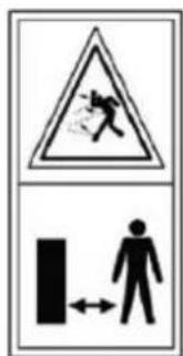
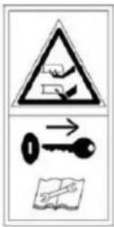
WARNING - Read user instructions before operating the machine
WARNING - Keep a safe distance from the machine when operating
WARNING - Remove (Operate) the disabling device before working on or lifting the machine.
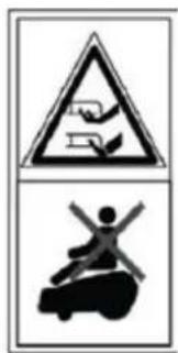
WARNING – Do not ride on the machine
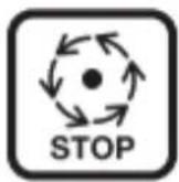
Wait until all machine components have completely stopped before touching them. The blades continue to rotate after the machine is switched off, a rotating blade can cause injury.
Do not use a high -pressure washer or a garden hose to clean the machine.
Check the perimeter wire is fully pegged to the ground avoi ding any slack lengths of wire.
Any loose wire can be a trip hazard.
Never:
- Store the equipment in a cold place. Instead, store it in room temperature.
Place the equipment next to a heat radiating unit, high temperature or fire.
- Remove the product casing (warranty void).
Have direct hit or strong vibration onequipment.
Use the equipment if any connector is broken.
- Touch the equipment or peripherals with wet hands.
Use the equipment in wet grass or during thunderstorm.
Let children or pets be in the vicinity of the equipment.
- Put hands or feet near the blades.
- Lift or carry the mower if the blades are moving.
Use the mower if any of the safety mechanisms is broken.
Use the charger if the power cord is broken.
Detach the charger by pulling on the cord. Take a firm grip of the connector and pull out.
Try to fix a broken power cord or the mower yourself. Always turn it in for authorized service at the reseller.
Important Notes When Using The Mower:
1) Make sure there are no items or vegetation (e.g. dropped pine cones) that might damage the mower on the lawn.
2) The mower does not work if the slop angle is more than 45^ .
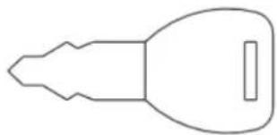
3) Remove the power key from the mower when it is not in use.
4) It is important to supervise the mower while working in order to avoid possible hazard situations.
5) In emergency situations, press the emergency stop on top of the mower.
6) Please power off when not use mower, If long time no use, please charge the mower every 3 months.
natural_image
Line drawing of a robotic car with wheels and a central circular component (no text or symbols)1xMachine
natural_image
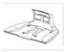
Technical line drawing of a mechanical component or housing (no text or symbols)1xCharge station
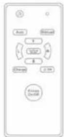
1x Remote control
natural_image
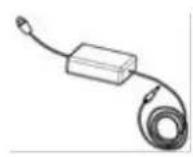
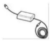
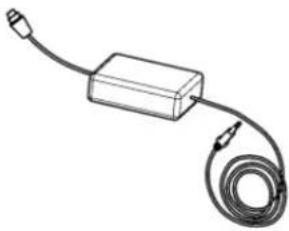
Simple line drawing of a rectangular device connected to a coiled cable (no text or symbols)1xAdaptor
natural_image
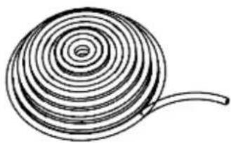
Simple line drawing of a spiral shell with a curved tail (no text or symbols)100mxFence line
natural_image
Simple line drawing of a key shape with no text or symbols1x Key
5xPeg for Charge station
100 xPeg for wire
3xBlade
1xSpanner
1xScrewdriver
Installation
Note: The charging station should be positioned on the outer edge of the surface to be mowed on the boundary wire. It can not be positioned next to a storage room or a garden house placed like an island in the middle of the surface to be mowed.
Note: The maximum distance between the boundary wire and the mower robot in the mowing area must not exceed 16 m.
Define objects buried more than 5 cm in the lawn such as ex. ponds, flowerbeds, etc.) in a clockwise direction around the object
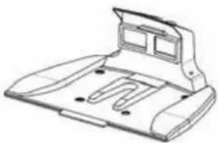
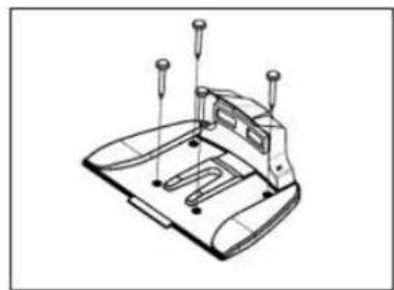
1. Installation of Charging
Station:
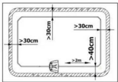
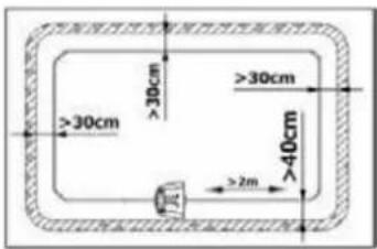
A) The location of charging station must be even, firm and convenient to use the power source. There are must be no obstacles or corners within 2 meters in front.
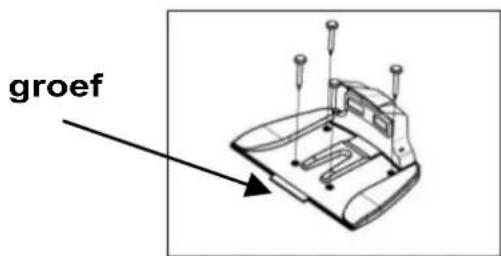
B) First fix the front part of the fence line under the charging station. The distance to the lawn edge should not less than 40cm. Then correspond the fence line to the grooves under the charging station, and fix the charging station with pegs.
natural_image
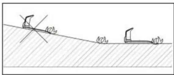
Technical line drawing of a mechanical component with mounting holes and a base plate (no text or symbols)Note: The charging station must facethe anticlockwise direction of the fence line. The charging station is forbidden to be put on any inclined surface
flowchart
graph TD
    A["Start"] --> B{Condition}
    B --> C["Process Box 1"]
    B --> D["Process Box 2"]
    C --> E["End"]
    D --> E
    style A fill:#f9f,stroke:#333
    style B fill:#ccf,stroke:#333
    style C fill:#cfc,stroke:#333
    style D fill:#fcc,stroke:#333
natural_image
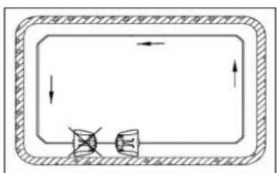
Simple line drawing of two vehicles on a slope with no text or symbols2. Installation of Fence Line:
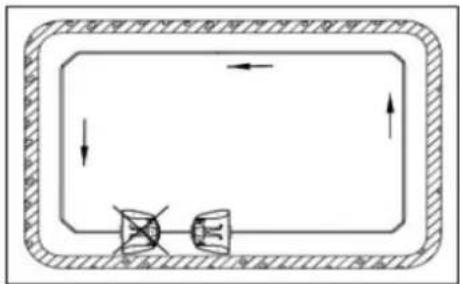
A) The fence line starts under the charging station, wiring in the antidockwise direction along the lawn edge. It ends at the back side of the charging station.
B) The fence line must pass through the middle of the charging station, and forward at least 2 meters (A).
C) The slimmest distance of wirings must be at least 1.5 meters interval. (B).
D) The fence line corner must have an inner angle of at least 125^ .
E) When there is a fixing facility or flower and tree in the lawn, isolate it as semi-ring-like island or ring-like island with the fence line to avoid any hit
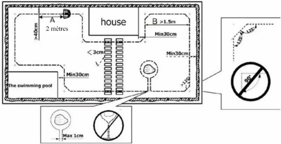
F) Except the front 2 meters of the fence line from the charging station, the distance of the rest fence line to the lawn edge is not less than 30cm.
G) Fix the fence line tightly against the ground with the provided pegs. It is recommended that the pegs are inserted every 2-3 meters. The pegs can be put even closer together if the ground elevation differs greatly.
natural_image
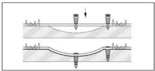
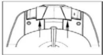
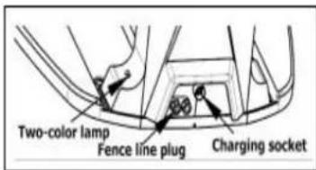
Diagram showing two mechanical or structural configurations with springs and a curved base, no text or symbols present.H) After all the fence line is fixed, reserve 10-15cm terminals respectively for both front and tail ends. Strip the terminals to reveal the copper lines for 2-3cm (Fig. A). Remove the nuts, fasten the copper lines on copper conductors. Then tighten the nuts (Fig.B). Front tail connect with the red pole, rear tail connect with the black pole. When the charger is connected to the charging station and the fence line starts to operate, the red lamp should be off.
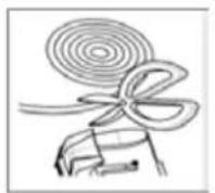
Fig. A
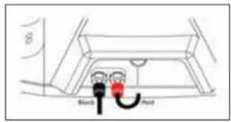
Fig. B
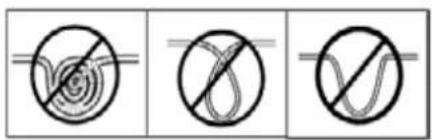
Fig. C
Note: Do not fold or repeat wiring with the rest fence line. Cut it instead (Fig. C)
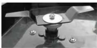
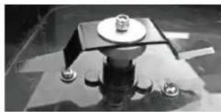
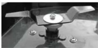
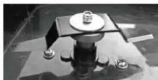
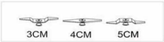
Mowing Height:
The mowing height can be adjusted by changing the blades or adjust its position. There are 3 mowing heights using 2 different kinds blades. Detach the blade with a spanner and attach it again into the desired position.
Note : Make sure that the power key and fuse are not inserted.
Charging:
The mower can be charged in the charging station. The extruding poles of the mower should be in contact with the respective paddles of the charging station. If the mower need to be charged, the mower will find its way to the station for charging automatically when it needs to recharge.
The mower can be charged directly by connecting the charger to the charger input in back of the mower.
Note:
- The charger plugs must be well connected to the charging station and tighten the nuts;
• The battery must be fully charged before the use first time;
• The two paddles of the charging station are electrified (24V DC). - To avoid short circuit, they must never be touched with conductor when the charger is connected to the charging station.
natural_image
Technical line drawing of a mechanical component with arrows indicating motion or force direction (no text or symbols)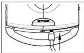
Operation:
On:
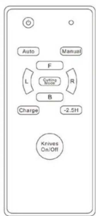
Place the mower inside of the fence line area . Insert the key and start the power. Press the remote Power
fence line and the mower clockwise direction to the charge station. Then press Auto button. The mower drives to the charging station along the fence line. When the extruding poles contact with the paddles, it will retreat to the lawn automatically for mowing operation in auto pattern.
. The mower can be controlled by remote in the following way:
a) Place the mower on the fence line in clockwise direction.
Turn on the power key. When a buzzing sound is heard,
press the remote with ⏻ button and then press Auto button.
The mower starts to work in auto pattern.
b) Press Charge button to command the mower back to the
charging station for charging. When it is fully charged, press button and then Auto button, the mower will continue back to lawn to work in auto pattern.
c) When working in auto pattern, press Manual button to change to manual pattern. Press F button for forward, B button for backward, L button for left and R button for right. Press Knives button for on/off of blades. When working in manual pattern, press Autot button to change back to auto pattern.
d) Press ⏻ button for pause. To restart the auto pattern, press ⏻ button first and then Auto button.
e) When we go into the manual model, please press Cutting Model. The mower goes into spiral working mode. F and B button make The mower goes ahead or goes back. L or R make the mower go left or right.
Note:
☐ The direction buttons and Knives button can only be applied when in manual pattern.
□ When go back to the charging station automatically or manually in manual pattern, F button and B button is void. But R button and L button are still valid.
☐ The remote is not available when the mower drives on or within 20cm near from the fence line.
☐ Please remove the remote battery if the remote is not used for a long time.
☐ There is no function for button "-2.5H" in the remote.
Troubleshooting:
1. The mower does not start.
a) The mower starts in an ineffective fence line area. Check the fence line for repair.
b) Check the emergency stop switch. If the emergency stop switch is locked, press the emergency stop switch then press red power switch.
c) If the mower has not been used for a long while, the battery may be empty. Make sure to charge it again after charging. Even when unused, it is recommended that the battery is charged every 3 months.
2. The mower does not move forward.
a) The bumper might be stuck. Please turn off the mower and check the bumper. If the bumper was broken or the sensor tube was sheltered by dirt, please use thing to clean it. if the switch is returned to the start position after being pushed. If it can not be back to position when push you should remove possible objects or grass that has been stuck in the bumper. b) If the grass is very long at the first time, which will shelter the sensor tube, please mow the grass with a traditional lawn mower before using the robot mower.
3. The mower does not mow properly or at all.
a) Turn off the mower. Check if the blades are properly installed.
Replace the blades if damaged.
b) If the mower is in a slope which has an angle more than 45^ , the mower will automatically stop.
c). The root part of the blade holder is stuck by objects or grass. Remove them and restart.
d) The grass is too dense to be mowed due to the automatic protection of machine.
4. The mower crosses the fence line and continues outside the perimeter.
a) The fence line turn angle is too steep. The inner angle must be at least 125^ .
b) The fence line is too close to a slope. Adjust the fence line position to be in accordance to the recommendations.
C) The fence line signal is weak. The fence line must not exceed 200m.
5. The battery is not charging.
a) The extruding poles of the charger are not in contact with the paddles of the charging station.
b) The extruding poles or the paddles are dirty. Clean them. (Make sure to disconnect the power before cleaning.)
c) If long time no charge, the left power will be exhausted by itself. If the battery broken a little you can re-charge many times to active the battery or you can change the battery.
6. The mower does not return to the charging station for charging.
a) The fence line is too long. The battery lever is not enough to return the mower to the charging station. Turn off the mower and carry it to the station.
b) If the mower was stopped by obstacle it will stop working
Functions
A) S elect the mowing route intelligently;
B) Avoid collisions intelligently;
C) Take shelter from rain intelligently;
D) Return to charging station for charging intelligently;
E) Safe protection intelligently.
Technical Specifications
| Model | Rob MR08Z |
| Cut | 590x580x230 mm |
| Operating voltage | 24V |
| Cutting power | 140W |
| Engine speed | 5000 min ^-1 |
| Loading time | +/- 4h30 |
| Average operating time | +/- 2h30 |
| Cutting width | 320 mm |
| Cutting height - 3 positions | 30-50mm |
| Mowing capacity for each recharge | 500 m ^2 |
| Protection class | IPX 1 |
| Insulation class | III |
| Loading station | Entrance AC100 -240V 1500mA 50/60HzOutput: DC24V -DC29.4V 1.5°IP 67 |
| Battery for remote control | 1x 23A 12V |
| Noise | LWA 73 dB |
| Weight | 9.85 Kg |

ATTENTION!
The sound power pressure may exceed 85 dB(A), in this case individual hearing protection must be worn.

The declared vibration total value has been measured in accordance with a standard test
method and may be used for comparing one tool with another that the declared vibration total value may also be used in a preliminary assessment of exposure.

A warning that the vibration emission
during actual use of the power tool can differ from the
declared total value depending on the ways in which the tool is used and of the need to identify safety measures to protect the operator that are based on an estimation of exposure in the actual conditions of use (taking account of all parts of the operating cycle such as the times when the tool is switched off and when it is running idle in addition to the trigger time).
STORAGE
_ Thoroughly clean the whole machine and its accessories.
_ Store it out of the reach of children, in a stable and secure position, in a cool and dry place, avoid too high and too low temperatures.
Protect it from exposure to direct sunlight. Keep it in the dark, if possible.
_ Don't keep it in plastic bags to avoid humidity build-up.
Battery storage
_ Store your batteries in a cool place. The optimal temperature to store your Li-ion battery for a long time is 10^ (the loss of capacity will be only 6% per year ( 20% loss at 38^ ) Never store the batteries when they are unloaded.
_ It is best to recharge the Li-ion batteries often when discharged. An optimal charge in case of prolonged storage for your Li-ion battery is 40% of its capacity.
ENVIRONMENT
Should your machine need replacement after extended use, do not put it in the domestic waste but dispose of it in an environmentally safe way.
You must dispose of the used machine in an environmentally friendly manner and in compliance with local regulations.
☐ Download the battery by rotating the vacuum machine until the engine stops. ☐ Deliver the machine as a small chemical waste to the ecological treatment depot of your municipality.
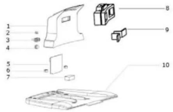
1 Top cover
2 Indicator light
3 Terminals
4 Charger plug
5 PCB
6 PCB clasp
7 Battery
8 Charging piece support
9 Charge piece
10 Recharge stand baseboard
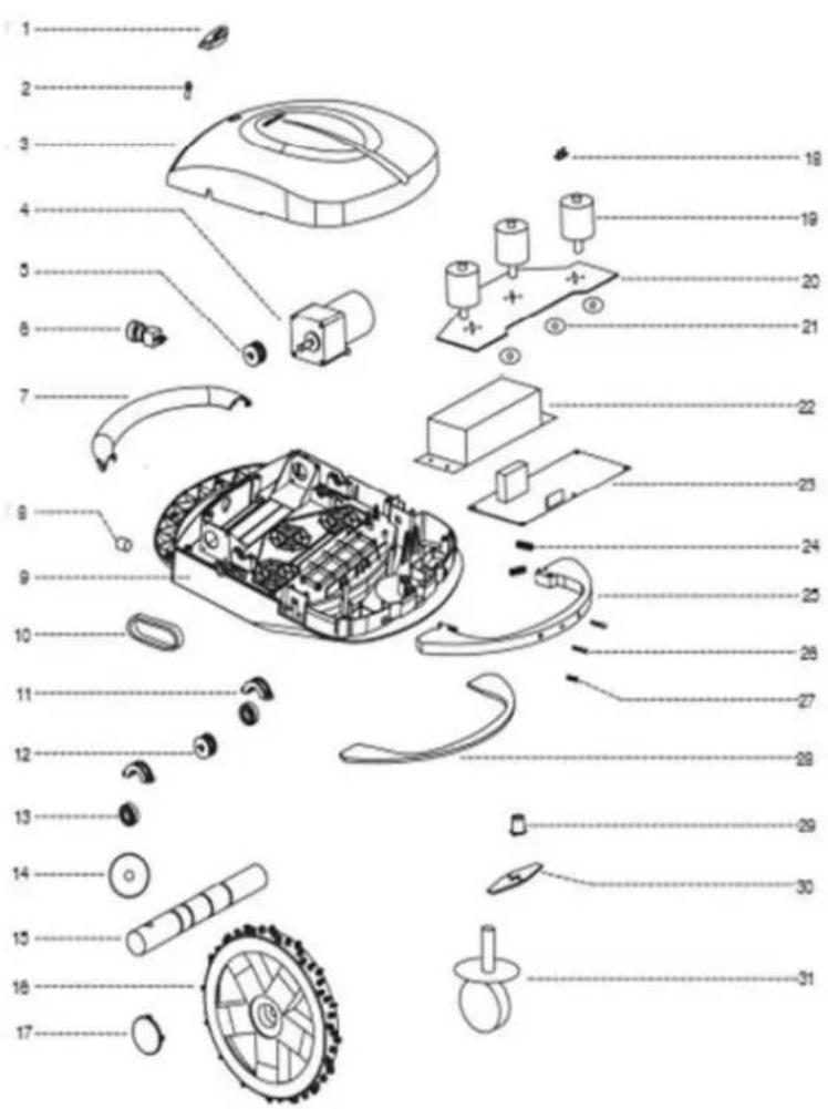
- Switch cover
- Emergency Switch
3.Cover - Running motor
- Gear1
- Powerlock
- Handle
- Charge plug
- Basis
10.Chain
11.Bearing cover
12.Gear2
13.Bearing
14.Rubber ring
15.Driving shaft
16.Wheel
17.Wheel cover
18.Rain sensor
19.Cutting motor
20.Motor fixed plate
21.Oil seal ring
22.Battery
23.CPU
24.Spring
25.Bumper - Charge column
27.Bumper sensors
28.Seal cushion
29.Blade fixed device
30.Blade
31.Direction wheel