WKM - Faucet STIEBEL ELTRON - Free user manual and instructions
Find the device manual for free WKM STIEBEL ELTRON in PDF.

| Product type | Mixing faucet for sink |
| Brand | Stiebel Eltron |
| Model | WKM |
| Application | Kitchen |
| Mounting type | Wall-mounted faucet |
| Surface | Chrome |
| Max. flow rate | 18 l/min |
| Max. admissible pressure | 1 MPa (10 bar) |
| Reach | 160 mm |
| Connection | G 1/2 |
| Main functions | Two control handles for hot/cold water mixing; spout equipped with a flow regulator |
| Usage | Operate the right handle for hot water, left for cold water; mix to adjust temperature |
| Care and cleaning | Clean with a damp cloth; do not use abrasive or solvent cleaners; descale the flow regulator by removing it |
| Safety | Outlet temperature may exceed 60 °C: risk of burns above 43 °C; do not block the water outlet to avoid pressurizing the tank |
| Compatibility | Free-flow domestic hot water tank for sink |
| Warranty | Consult local warranty conditions; use of original parts recommended |
| Recycling | Dispose of in accordance with national regulations |
Frequently Asked Questions - WKM STIEBEL ELTRON
User questions about WKM STIEBEL ELTRON
0 question about this device. Answer the ones you know or ask your own.
Ask a new question about this device
Download the instructions for your Faucet in PDF format for free! Find your manual WKM - STIEBEL ELTRON and take your electronic device back in hand. On this page are published all the documents necessary for the use of your device. WKM by STIEBEL ELTRON.
USER MANUAL WKM STIEBEL ELTRON
BEDIENUNG UND INSTALLATION OPERATION AND INSTALLATION UTILISATION ET INSTALLATION BEDIENING EN INSTALLATIE OBSLUHA A INSTALACE OBSŁUGA I INSTALACJA
Armatur für offene (drucklose) Warmwasserspeicher | Tap for open vented (non-pressurised) water heaters | Mitigeur pour ballons d'eau chaude sanitaire à écoulement libre | Kraan voor open (drukloze) warmwaterboilers | Baterie pro otevřené (beztlaké) zásobníky teplé vody | Armatury do otwartych (bezciśnieniowych) zasobników ciepłej wody
» WKM
» WDM
» WBM
natural_image
Pure mechanical assembly diagram showing two vertical rods connected to a central bracket (no text or symbols)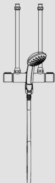
natural_image
Technical line drawing of a showerhead with two vertical connectors and a central handle (no text or symbols)
natural_image
Line drawing of a laboratory apparatus with a bulb, funnel, and stand (no text or symbols)BEDIENUNG
natural_image
Technical line drawing of a mechanical component with a central cylindrical body and upward arrow indicator (no text or symbols)text_image
Technical diagram of a mechanical device with numbered components, likely for assembly or labeling.natural_image
Technical line drawing of a mechanical assembly with two cylindrical components and diagonal lines (no text or symbols)text_image
Technical diagram of a showerhead assembly with numbered parts and a directional arrow indicating motion or adjustment.- General information 10
1.1 Safety instructions 10
1.2 Other symbols in this documentation ____ 10
1.3 Units of measurement 11 - Safety 11
2.1 Intended use 11 - Operation 11
- Cleaning and care 11
INSTALLATION
- Safety 12
5.1 General safety instructions 12
5.2 Instructions, standards and regulations ____ 12
6. Appliance description 12
7. Installation 13
8. Commissioning 14
8.1 Checking the maximum flow rate 14
9. Specification 14
9.1 Dimensions and connections 14
9.2 Data table 15
GUARANTEE
ENVIRONMENT AND RECYCLING
OPERATION
1. General information
The chapter "Operation" is intended for appliance users and qualified contractors.
The chapter "Installation" is intended for qualified contractors.

Note
Read these instructions carefully before using the appliance and retain them for future reference.
Pass on the instructions to a new user if required.
1.1 Safety instructions
1.1.1 Structure of safety instructions

KEYWORD Type of risk
Here, possible consequences are listed that may result from failure to observe the safety instructions.
▶ Steps to prevent the risk are listed.
1.1.2 Symbols, type of risk
| Symbol | Type of risk |
 | Burns(burns, scalding) |
1.1.3 Keywords
| KEYWORD | Meaning |
| DANGER | Failure to observe this information will result in serious injury or death. |
| WARNING | Failure to observe this information may result in serious injury or death. |
| CAUTION | Failure to observe this information may result in non-serious or minor injury. |
1.2 Other symbols in this documentation

Note
General information is identified by the symbol shown on the left.
▶ Read these texts carefully.
| Symbol | Meaning |
 | Material damage(Appliance and consequential losses, environmental pollution) |
 | Appliance disposal |
This symbol indicates that you have to do something. The action you need to take is described step by step.
1.3 Units of measurement

Note
All measurements are given in mm unless stated otherwise.
2. Safety
2.1 Intended use
This product is intended for operation with an open vented (non-pressurised) oversink water heater.
- WKM for kitchen sinks
- WDM for showers
- WBM for baths
This product is designed for domestic use. It can be used safely by untrained persons. The appliance can also be used in a non-domestic environment, e.g. in a small business, as long as it is used in the same way.
Any other use beyond that described shall be deemed inappropriate. Observation of these instructions is also part of the correct use of this appliance.
3. Operation

Note
When the water in the water heater is being heated, expansion water will drip from the outlet.
With non-pressurised water heaters with anti-drip function, the expansion water remains inside the water heater.
Turn the right handle to draw off hot water.
Turn the left handle to draw off cold water.
To achieve the required temperature, turn both handles and adjust the mix of cold and hot water by increasing or reducing the respective flow rates.
WBM: You can switch between spout and hand shower. For this, pull the diverter upwards while the water is running.
The tap automatically reverts to the original position after draw-off has ended.
natural_image
Technical diagram of a mechanical component with a central cylindrical body and two arrows indicating upward and downward motion (no text or symbols)4. Cleaning and care
▶ Never use abrasive or corrosive cleaning agents. A damp cloth is sufficient for cleaning and caring for the product.
▶ For descaling, remove the aerator from the fitting.
INSTALLATION
5. Safety
Only qualified contractors should carry out installation, commissioning as well as maintenance and repair of the product.
5.1 General safety instructions
We guarantee trouble-free function and operational reliability only if original accessories and spare parts intended for the product are used.

WARNING Burns
During operation, the tap can reach temperatures in excess of 60 °C .

Material damage
Scale build-up can block the outlet and thus subject the water heater to pressure.
▶ Never block the spout, and use only aerators for non-pressurised taps, otherwise the water heater could be damaged.
5.2 Instructions, standards and regulations

Note
Observe all applicable national and regional regulations and instructions.
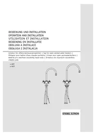
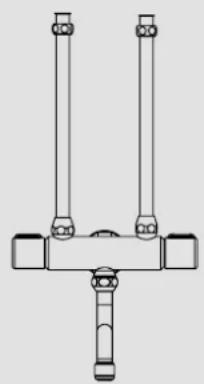
6. Appliance description
Standard delivery
WBM illustration
text_image
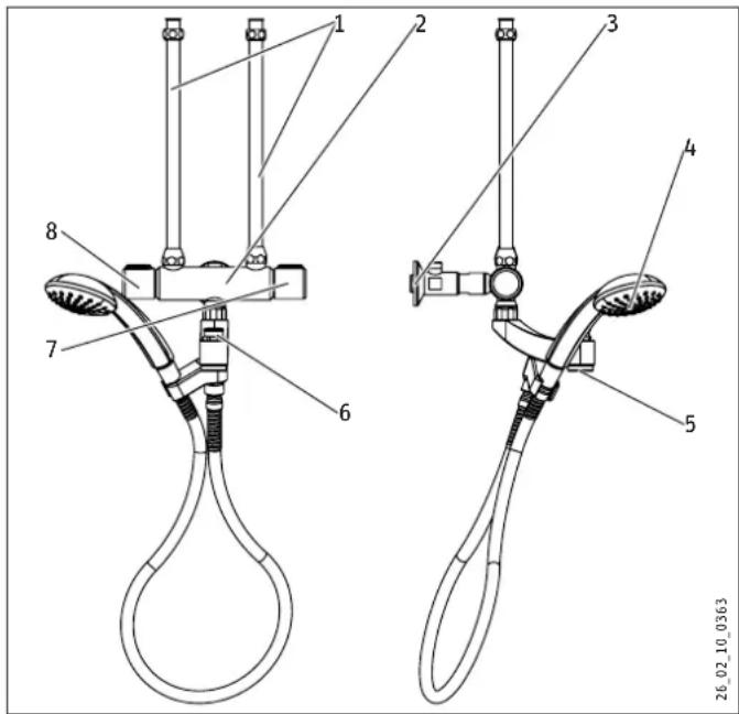
Technical diagram of a mechanical device with numbered components, likely for assembly or maintenance instructions.1 Water inlet pipe
2 Tap body
3 Wall connection with butterfly valve and tap extension
4 WDM | WBM: Hand shower with retainer
5 WKM | WBM: Spout with aerator
6 WBM: Changeover: Hand shower - outlet
7 Handle for hot water
8 Handle for cold water
7. Installation

Material damage
The water heater can leak.
▶ Never subject the water heater to water pressure.
▶ Ensure the shower hose is not kinked.
▶ Deburr the pipes if you have reduced them.
▶ Thoroughly flush the cold water supply line.
text_image
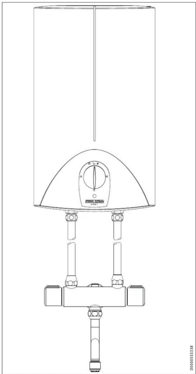
H 5m H M V STEEL BUTTON 12-04-1 D000033338▶ Attach the water inlet pipes to connect the water heater with the tap body.
natural_image
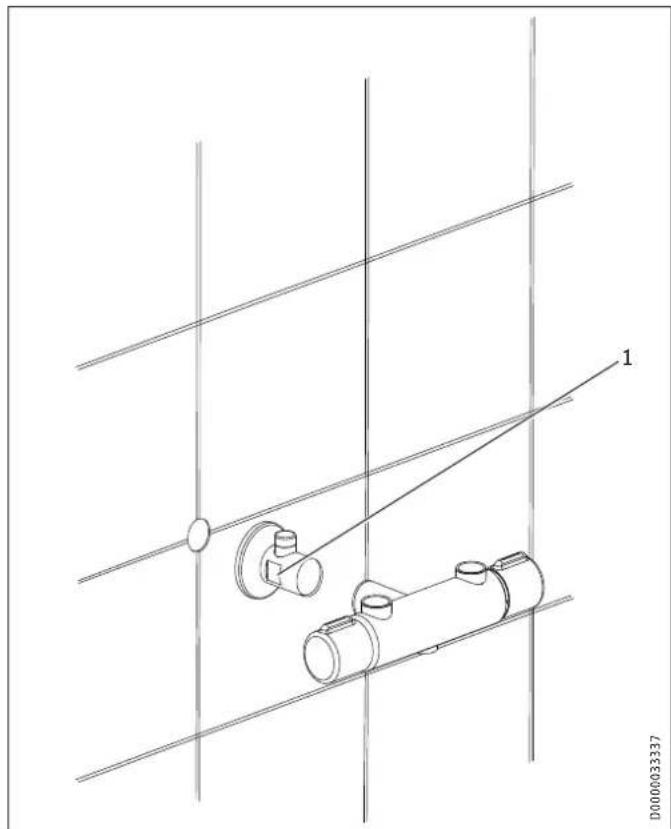
Technical line drawing of a mechanical assembly with two cylindrical components and diagonal lines (no text or symbols)1 Spanner size 24
For water heaters with more than 30 l capacity, insert the tap extension between the wall connection and the tap body if required.
text_image
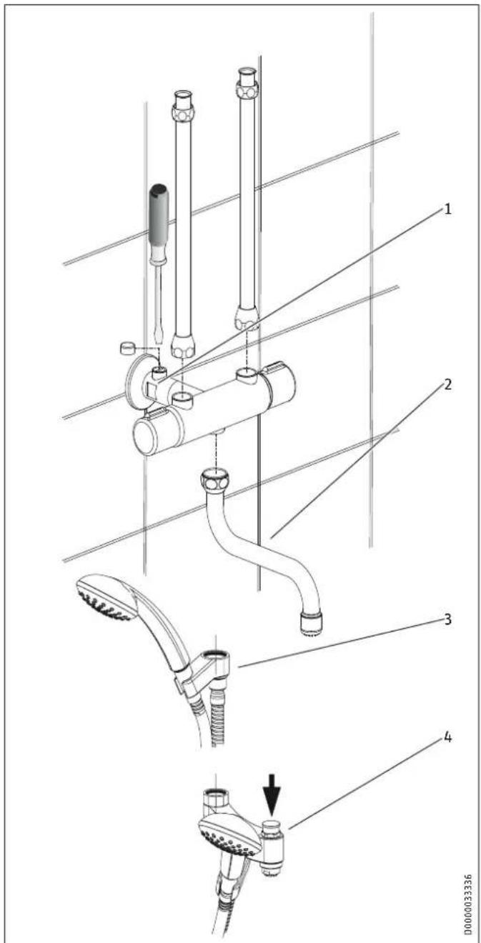
Technical diagram of a showerhead assembly with numbered parts and a directional arrow indicating motion or adjustment.1 Butterfly valve with adjusting screw
2 WKM
3 WDM
4 WBM
▶ Fit the following onto the tap body:
- WKM: Pivoting spout
- WDM: Shower hose with retainer for hand shower
- WBM: Pivoting arm with shower hose and retainer for hand shower
8. Commissioning
▶ Thoroughly flush the cold water supply line.
▶ Filling the water heater: Open the DHW valve.
▶ Wait until water flows from the outlet, then switch on the water heater.
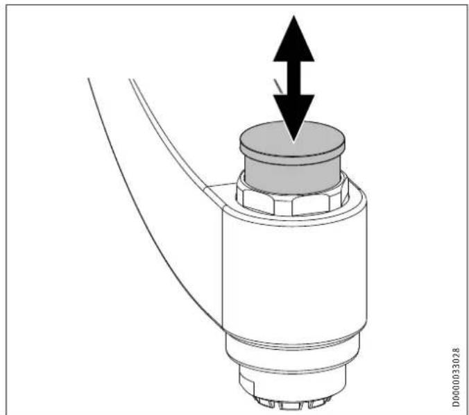
8.1 Checking the maximum flow rate

Material damage
With non-pressurised water heaters, observe the maximum permissible flow rate when the tap is fully open (see chapter "Specification / Data table").
▶ If the flow rate exceeds the stated value when the tap is fully open, reduce the flow via the butterfly valve in the wall connection.
▶ For this, remove the cap and turn the adjusting screw clockwise with a screwdriver.
9. Specification
9.1 Dimensions and connections
WKM
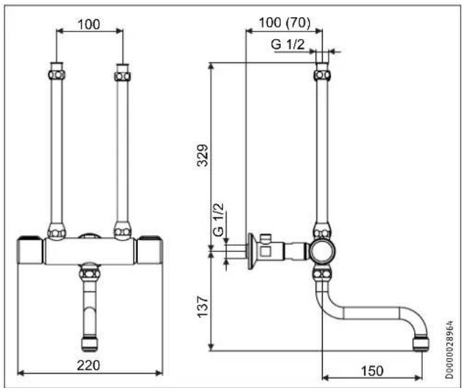
text_image
100 220 100 (70) G 1/2 329 G 1/2 137 150 D0000028964WDM
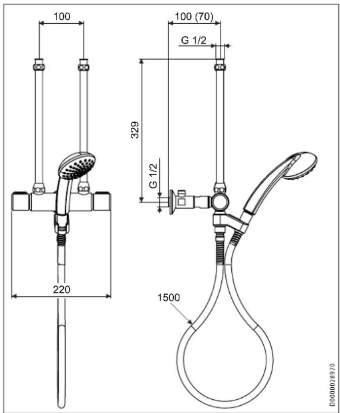
text_image
100 100 (70) G 1/2 329 G 1/2 220 1500 D00000289709.2 Data table
| WKM WDM WBM | ||||
| 232605 232606 232607 | ||||
| Application | Kitchen | Shower | Shower/ bath | |
| Type | open | open | open | |
| Type of installation | Wall mounted mixer tap | Wall mounted mixer tap | Wall mounted mixer tap | |
| Surface | chrome finish | chrome finish | chrome finish | |
| Max. throughput | l/min | 18 | 18 | 18 |
| Max. permissible pressure | MPa | 1 | 1 | 1 |
| Reach | mm | 160 | 86 | |
▶ Bear in mind that, depending on the static pressure, you may also need a pressure reducing valve.
WBM
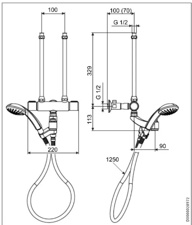
text_image
100 100 (70) G 1/2 329 G 1/2 113 220 90 1250 D0000028972Guarantee
The warranty conditions of our German companies do not apply to appliances acquired outside of Germany. In countries where our subsidiaries sell our products, it is increasingly the case that warranties can only be issued by those subsidiaries. Such warranties are only granted if the subsidiary has issued its own terms of warranty. No other warranty will be granted.
We shall not provide any warranty for appliances acquired in countries where we have no subsidiary to sell our products. This will not affect warranties issued by any importers.
Environment and recycling
We would ask you to help protect the environment. After use, dispose of the various materials in accordance with national regulations.
UTILISATION
natural_image
Technical diagram of a mechanical component with a central cylindrical part and two arrows indicating upward and downward motion (no text or symbols)text_image
Technical diagram of a mechanical device with numbered components, likely for assembly or maintenance instructions.natural_image
Technical line drawing of a mechanical assembly with two cylindrical components and diagonal lines (no text or symbols)text_image
Technical diagram of a showerhead assembly with numbered parts and a directional arrow indicating motion or adjustment.- WKM: le bec orientable
natural_image
Technical line drawing of a mechanical component with a central cylindrical part and two arrows indicating upward and downward motion (no text or symbols)4. Reiniging en verzorging
WAARSCHUWING verbranding
text_image
Technical diagram of a mechanical device with numbered components, likely for assembly or labeling.natural_image
Technical line drawing of a mechanical assembly with two cylindrical components and diagonal lines (no text or symbols)1 Sleutelmaat 24
text_image
Technical diagram of a showerhead assembly with numbered parts and a directional arrow indicating motion or adjustment.natural_image
Technical diagram of a mechanical component with a central cylindrical part and two arrows indicating upward and downward motion (no text or symbols)4. Čištění a péče
text_image
Technical diagram of a mechanical device with numbered components, likely for assembly or maintenance instructions.natural_image
Technical line drawing of a mechanical assembly with two cylindrical components and diagonal lines (no text or symbols)1 Klič 24
text_image
Technical diagram of a showerhead assembly with numbered parts and a directional arrow indicating motion or adjustment.natural_image
Technical diagram of a mechanical component with a central cylindrical part and two arrows indicating upward and downward motion (no text or symbols)text_image
Technical diagram of a mechanical device with numbered components, likely for assembly or labeling.text_image
Technical diagram of a showerhead assembly with numbered parts and a directional arrow indicating motion or adjustment.Rm 102, F1, Yingbin-Yihao Mansion, No. 1
Yingbin Road
Panyu District | 511431 Guangzhou
Tel. 020 39162209 | Fax 020 39162203
info@stiebeleltron.cn
www.stiebeleltron.cn
Czech Republic
STIEBEL ELTRON spol. s r.o.
Urzhumskaya street 4,
building 2 | 129343 Moscow
Tel. 0495 7753889 | Fax 0495 7753887
info@stiebel-eltron.ru
www.stiebel-eltron.ru
Slovakia
TATRAMAT - ohrievače vody, s.r.o.
Hlavná 1 | 058 01 Poprad
Tel. 052 7127-125 | Fax 052 7127-148
info@stiebel-eltron.sk
www.stiebel-eltron.sk
Switzerland
STIEBEL ELTRON AG
Industrie West
Gass 8 | 5242 Lupfig
Tel. 056 4640-500 | Fax 056 4640-501
info@stiebel-eltron.ch
www.stiebel-eltron.ch
Thailand
STIEBEL ELTRON Asia Ltd.
469 Moo 2 Tambol Klong-Jik
Amphur Bangpa-In | 13160 Ayutthaya
Tel. 035 220088 | Fax 035 221188
info@stiebeleltronasia.com
www.stiebeleltronasia.com
United Kingdom and Ireland
STIEBEL ELTRON UK Ltd.
Unit 12 Stadium Court
Stadium Road | CH62 3RP Bromborough
Tel. 0151 346-2300 | Fax 0151 334-2913
info@stiebel-eltron.co.uk
www.stiebel-eltron.co.uk
United States of America
STIEBEL ELTRON, Inc.
17 West Street | 01088 West Hatfield MA
Tel. 0413 247-3380 | Fax 0413 247-3369
info@stiebel-eltron-usa.com
www.stiebel-eltron-usa.com