Optimate Solar - Battery charger Tecmate - Free user manual and instructions
Find the device manual for free Optimate Solar Tecmate in PDF.

| Product type | Solar battery charger |
| Brand | TecMate |
| Model | Optimate Solar |
| Category | Battery charger |
| Nominal voltage | 12 V (DC) |
| Compatible panel power | 2 W to 15 W (12 V solar panel) |
| Maximum charge current | Up to 5 A in pulse mode |
| Compatible battery types | Lead-acid batteries (standard, AGM, high performance) |
| Non-compatible batteries | NiCd, NiMH, Li-Ion, non-rechargeable dry cells |
| Charge modes | Recovery (Red), Main charge (Yellow), Float maintenance (Green) |
| Battery monitoring function | Charge status indication via LED (5 levels) |
| Protection | Against reverse polarity, short circuits (built-in 15A fuse) |
| Supplied connectors | Alligator clips and ring terminals with waterproof cap |
| Usage | Indoor use only, do not expose to rain or snow |
| Operating temperature | Not specified (avoid freezing) |
| Maintenance | Clean terminals with a copper brush or cloth; check connections regularly |
| Safety | Read instructions before use; work in a ventilated area; avoid flames/sparks |
| Warranty | 3 years, limited (component or assembly defects) |
| Specific features | Pulse charging for sulfated battery recovery |
| Optional accessories | Suitable solar panel (2-15W) |
Frequently Asked Questions - Optimate Solar Tecmate
User questions about Optimate Solar Tecmate
0 question about this device. Answer the ones you know or ask your own.
Ask a new question about this device
Download the instructions for your Battery charger in PDF format for free! Find your manual Optimate Solar - Tecmate and take your electronic device back in hand. On this page are published all the documents necessary for the use of your device. Optimate Solar by Tecmate.
USER MANUAL Optimate Solar Tecmate
Automatic solar charge controller & monitor
natural_image
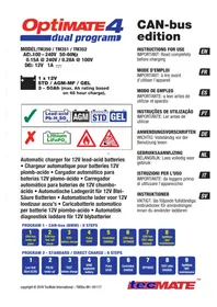
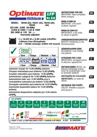
Exterior view of a 12V charging device with a terminal plug and cable (no visible text or symbols)MODEL : TM-522 Solar charge controller and battery monitor for 12V lead-acid batteries, for solar panels from 10–30W.
IN: 12V SOLAR PANEL 10-30W
OUT : DC output voltage : 12V ---
DC output current : 2.5A max.
MODEL: TM-523 Solar charge controller and battery monitor for 12V lead-acid batteries, for solar panels from 40–80W.
-#: 12V SOLAR PANEL 40-84W
OUT : DC output voltage : 12V
DC output current : 7A max.
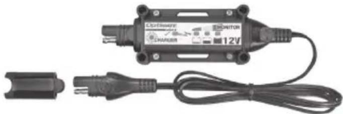
OptiMate Solar charge controller-monitor and panel kits
natural_image
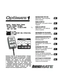
Electrical wiring diagram showing a solar panel connected to an inductor with two test probes (no text or symbols visible)Models: TM522-1 : TM522 + TM525 10W polycrystalline panel OUT: 12V 0.83A max.
TM522-2 : TM522 + TM526 20W polycrystalline panel OUT: 12V 1.67A max.
TM522-3 : TM522 + TM527 30W polycrystalline panel OUT: 12V 2.50A max.
TM523-4 : TM523 + TM528 40W polycrystalline panel OUT: 12V 3.34A max.
TM523-5 : TM523 + TM529 50W polycrystalline panel OUT: 12V 4.17A max.
TM523-6 : TM523 + TM530 60W polycrystalline panel OUT: 12V 5.00A max.
TM523-8 : TM523 + TM531 80W polycrystalline panel OUT: 12V 6.67A max.
1 x Solar charge controller charges 1 x Lead-Acid battery
Battery types: Flooded STD with liquid acid electrolyte / removable filler caps / EFB
Sealed AGM-MF / GEL / CYCLIC CELL
INSTRUCTIONS FOR USE
IMPORTANT: Read completely before charging
MODE D'EMPLOI
natural_image
Simple line drawing of a sun with radiating ovals (no text or symbols)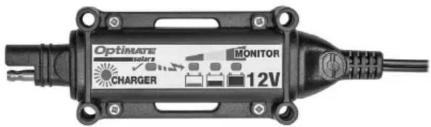
text_image
Optimare solar MONITOR CHARGER 12V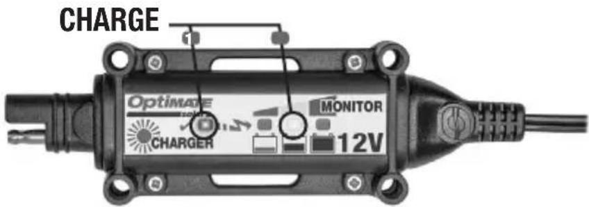
text_image
CHARGE Optimize MONITOR CHARGER 12V
natural_image
Simple line drawing of a sun with twelve ovals at the center (no text or symbols)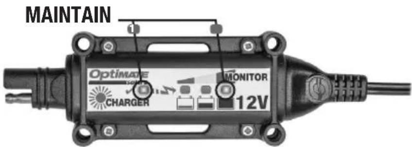
text_image
MAINTAIN Optimize Sensor CHARGER MONITOR 12V
text_image
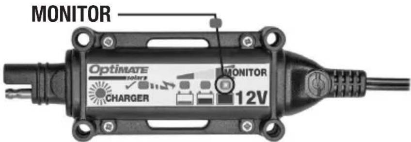
MONITOR Optimare solar CHARGER MONITOR 12VTHIS PORTION OF THE MANUAL CONTAINS IMPORTANT SAFETY INSTRUCTIONS FOR THE OPTIMATE SOLAR BATTERY CHARGER. IT IS OF THE UTMOST IMPORTANCE THAT EACH TIME, BEFORE USING THE CHARGER, YOU READ AND EXACTLY FOLLOW THESE INSTRUCTIONS. SAVE THESE INSTRUCTIONS.
AUTOMATIC CHARGER FOR 12V LEAD-ACID BATTERIES DO NOT USE FOR NiCd, NiMH, any other Li-Ion OR NON-RECHARGEABLE BATTERIES.
- CAUTION : 12V DC APPLIANCE. DO NOT CONNECT TO AC POWER.
- For indoor use only. Do not expose charger to rain or snow.
- Use of an attachment not recommended or sold by the battery charger manufacturer may result in a risk of fire, electric shock, or injury to persons.
- To reduce risk of damage to electric plug and cord, pull by plug rather than cord when disconnecting charger.
- An extension cord should not be used unless absolutely necessary. Use of improper extension cord could result in a risk of fire and electric shock. If extension cord must be used make sure that :
a) pins on plug of extension cord are the same number, size and shape as those of plug on charger.
b) the extension cord is property wired and in good electrical condition, and
c) the conductor wire size is large enough for the DC ampere rating of the charger as specified in the table below.
| DC INPUT RATING IN AMPERESEqual to or greater than But less than | LENGTH OF CORD, FEET (m) | AWG SIZE OF CORD | |
| 2A 3A 25 (17.6) | 50 (15.2)100 (30.5) | 181614 | |
- Do not operate charger with damaged cord or plug - replace the cord or plug immediately.
- Do not operate charger if it has received a sharp blow, been dropped, or otherwise damaged in any way; take it to a qualified serviceman.
- Do not disassemble charger; take it to a qualified serviceman when service or repair is required. Incorrect reassembly may result in a risk of electric shock or fire.
- To reduce risk of electric shock, unplug the charger from supply before attempting any maintenance or cleaning. Turning off controls will not reduce this risk. Clean only with slightly moist, not wet, cloth. Do not use solvents.
- WARNING – RISK OF EXPLOSIVE GASES.
a) WORKING IN VICINITY OF A LEAD-ACID BATTERY IS DANGEROUS. BATTERIES GENERATE EXPLOSIVE GASES DURING NORMAL BATTERY OPERATION. FOR THIS REASON, IT IS OF UTMOST IMPORTANCE THAT YOU FOLLOW THE INSTRUCTIONS EACH TIME YOU USE THE CHARGER.
b) To reduce risk of battery explosion, follow these instructions and those published by the battery manufacturer and manufacturer of any equipment you intend to use in vicinity of the battery. Review cautionary marking on these products and on engine.
11. PERSONAL PRECAUTIONS.
a) Someone should be within range of your voice OR close enough to come to your aid when you work near a lead-acid battery.
b) Have plenty of fresh water and soap nearby in case battery acid contacts skin, clothing or eyes.
c) Wear complete eye protection and clothing protection. Avoid touching eyes while working near battery.
d) If battery acid contacts or enters eye, flood eye with cold running water for at least 10 minutes and get medical attention immediately.
If battery acid contacts skin or clothing, wash immediately with soap & water. If acid enters an eye, immediately flood eye with running cold water for at least 10 minutes & get medical attention immediately.
e) NEVER smoke or allow a spark or flame in vicinity of battery or engine.
f) Be extra cautious to reduce risk of dropping a metal tool onto battery. It might spark or short-circuit battery or other electrical part that may cause explosion.
g) Remove personal metal items such as rings, bracelets, necklaces, and watches when working with a lead-acid battery.
A lead-acid battery can produce a short-circuit current high enough to weld a ring or the like to metal, causing a severe burn.
i) NEVER charge a frozen battery.
12. PREPARING TO CHARGE
a) If necessary to remove battery from vehicle to charge, always remove grounded terminal from battery first.
Make sure all accessories in the vehicle are off, so as not to cause an arc.
b) Be sure area around battery is well ventilated while battery is being charged. Gas can be forcefully blown away by using a piece of cardboard or other non-metallic material as a fan.
c) Clean battery terminals. Be careful to keep corrosion from coming in contact with eyes.
d) Add distilled water in each cell until battery acid reaches level specified by battery manufacturer. This helps purge excessive gas from cells. Do not overfill. For a battery without cell caps, such as valve regulated lead acid (VRLA) or absorbed glass mat (AGM) batteries, carefully follow manufacturer's recharging instructions.
e) Study all battery manufacturer's specific precautions such as removing or not removing cell caps while charging and recommended rates of charge.
f) Determine voltage of battery by referring to vehicle or other user's manual and BEFORE MAKING THE BATTERY CONNECTIONS, MAKE SURE THAT THE VOLTAGE OF THE BATTERY YOU ARE GOING TO CHARGE MATCHES THE OUTPUT VOLTAGE OF THE CHARGER.
13. CHARGER LOCATION.
a) Locate charger as far away from battery as DC cables permit.
b) Never place charger directly above battery being charged; gases from battery will corrode and damage the charger.
c) Never allow battery acid to drip on charger when reading gravity or filling battery. Do not operate charger in a closed-in area or restrict ventilation in any way.
d) Do not set a battery on top of charger. IMPORTANT: Place charger on a hard flat surface or mount onto a vertical surface. Do not place on plastic, leather or textile surface.
14. DC CONNECTION PRECAUTIONS
a) Connect and disconnect DC output clips only after setting any charger switches to off position and removing DC cord from supply. Never allow clips to touch each other, however should this happen no damage will result to the charger circuit & the automatic charging programme will just reset to «start».
b) Attach clips to battery and chassis as indicated in 15(e), 15(f), and 16(b) through 16(d).
NOTE : This battery charger has an automatic safety feature that will prevent it from operating if the battery has been inversely connected. Set charger switches to off position and/or remove DC cord from the DC supply, disconnect the battery clips, then reconnect correctly according to the instructions below.
15. FOLLOW THESE STEPS WHEN BATTERY IS INSTALLED IN VEHICLE. A SPARK NEAR A BATTERY MAY CAUSE BATTERY EXPLOSION. TO REDUCE RISK OF A SPARK NEAR BATTERY :
a) Position AC and DC cords so as to reduce risk of damage by hood, door or moving engine part.
b) Stay clear of fan-blades, belts,pulleys,and other parts that can cause injury to persons.
c) Check polarity of battery posts. POSITIVE (POS, P, +) battery post usually has larger diameter than NEGATIVE (NEG, N,−) post.
d) Determine which post of battery is grounded (connected) to the chassis. If negative post is grounded to chassis (as in most vehicles), see (e). If positive post is grounded to the chassis, see (f).
e) For negative-grounded vehicle, connect POSITIVE (RED) clip from battery charger to POSITIVE (POS, P, +) ungrounded post of battery. Connect NEGATIVE (BLACK) clip to vehicle chassis or engine block away from battery. Do not connect clip to carburetor, fuel lines, or sheet-metal body parts. Connect to a heavy gage metal part of the frame or engine block.
f) For positive-grounded vehicle, connect NEGATIVE (BLACK) clip from battery charger to NEGATIVE (NEG. N, -) ungrounded post of battery. Connect POSITIVE (RED) clip to vehicle chassis or engine block away from battery. Do not connect clip to carburetor, fuel lines, or sheet-metal body parts. Connect to a heavy gage metal part of the frame or engine block.
g) When disconnecting charger, turn switches to off, disconnect AC cord, remove clip from vehicle chassis, and then remove clip from battery terminal.
h) See operating instructions for length of charge information.
16. FOLLOW THESE STEPS WHEN BATTERY IS OUTSIDE VEHICLE. A SPARK NEAR THE BATTERY MAY CAUSE BATTERY EXPLOSION. TO REDUCE RISK OF A SPARK NEAR BATTERY :
a) Check polarity of battery posts. POSITIVE (POS, P, +) battery post usually has a larger diameter than NEGATIVE (NEG,N, -) post.
b) This battery charger has an automatic safety feature that will prevent it from operating if the battery has been inversely connected. The charger does not allow charge current unless a voltage of at least 1V is sensed.
c) Connect POSITIVE (RED) charger clip to POSITIVE (POS, P, +) post of battery.
d) Connect NEGATIVE (BLACK) charger clip to NEGATIVE (NEG, N, -) battery post of the battery.
e) Do not face battery when making final connection.
f) When disconnecting charger, always do so in reverse sequence of connecting procedure & break first connection while as far away from battery as practical.
g) A marine (boat) battery must be removed & charged on shore. To charge it on board requires equipment specially designed for marine use.
DO NOT USE FOR NiCd, NiMH, Li-Ion OR NON-RECHARGEABLE BATTERIES.
IMPORTANT: READ THE FOLLOWING INSTRUCTIONS BEFORE USING THE CHARGER This appliance can be used by children aged from 8 years and above and persons with reduced physical, sensory or mental capabilities or lack of experience and knowledge if they have been given supervision or instruction concerning use of the appliance in a safe way and understand the hazards involved. Children shall not play with the appliance. Cleaning and user maintenance shall not be made by children without supervision.
SAFETY WARNING AND NOTES: Batteries emit EXPLOSIVE GASES - prevent flame or sparks near batteries. Disconnect AC power supply before making or breaking DC/battery connections. Battery acid is highly corrosive. Wear protective clothing and eyewear and avoid contact. In case of accidental contact, wash immediately with soap and water. Check that the battery posts are not loose; if so, have the battery professionally assessed. If the battery posts are corroded, clean with a copper wire brush; if greasy or dirty clean with a rag damped in detergent. Use the charger only if the input and output leads and connectors are in good, undamaged condition. If the input cable is damaged, it is essential to have it replaced without delay by the manufacturer, his authorised service agent or a qualified workshop, to avoid danger. Protect your charger from acid and acid fumes and from damp and humid conditions both during use and in storage. Damage resulting from corrosion, oxidation or internal electrical short-circuiting is not covered by warranty. Distance the charger from the battery during charging to avoid contamination by or exposure to acid or acidic vapours. If using it in the horizontal orientation, place the charger on a hard, flat surface, but NOT on plastic, textile or leather. Use the fixing holes provided in the enclosure base to attach the charger to any convenient, sound vertical surface.
EXPOSURE TO LIQUIDS: This charger is designed to withstand exposure to liquids accidentally spilled or splashed onto the casing from above, or to light rainfall. Prolonged exposure to falling rain is inadvisable and longer service life will be obtained by minimizing such exposure. Failure of the charger due to oxidation resulting from the eventual penetration of liquid into the electronic components, connectors or plugs, is not covered by warranty.
BATTERY CONNECTIONS: 2 interchangeable connection sets are available, supplied with the charger is a set of battery clips for charging the battery off-vehicle, the other connection set comes with metal eyelet lugs for permanent connection to the battery posts, and re-sealable weatherproof cap on the connector that connects to the charger output cable. This connection set allows easy and sure connection of the charger to maintain the battery on-vehicle. The resealable weatherproof cap is designed to protect the connector from dirt and damp whenever the charger is not attached. Consult a professional service agent for assistance in attaching the metal eyelets to the battery posts. Secure the connector with weatherproof cap so that it cannot foul any moving part of the vehicle or the cable can be pinched or damaged by sharp edges. The in-line fuse in the eyelets connection set protects the battery against such accidental shorting across positive and negative conductors. Replace any burnt fuse only with a similar new fuse of 15A rating.
CONNECTING THE CHARGER TO THE BATTERY
-
Disconnect solar panel before making or breaking DC / battery connections.
-
If charging a battery in the vehicle with the battery clips, before making connections, first check that the battery clips can be safely and securely positioned clear from surrounding wiring, metal tubing or the chassis. Make connections in the following order:
First connect to the battery terminal not connected to the chassis (normally positive), then connect the other battery clip (normally negative) to the chassis well away from the battery and fuel line. Always disconnect in reverse sequence.
-
When charging a battery out of the vehicle with the battery clips, place it in a well ventilated area. Connect the charger to the battery: RED clamp to POSITIVE (POS, P or +) terminal and BLACK clamp to NEGATIVE (NEG, N or -) terminal. Make sure the connections are firm and secure. Good contact is important.
-
If the battery is deeply discharged (and possibly sulphated), remove from the vehicle and inspect the battery before connecting the charger for a recovery attempt. Visually check the battery for mechanical defects such as a bulging or cracked casing, or signs of electrolyte leakage. If the battery has filler caps and the plates within the cells can be seen from the outside, examine the battery
carefully to try to determine if any cells seem different to the others (for example, with white matter between the plates, plates touching). If mechanical defects are apparent do not attempt to charge the battery, have the battery professionally assessed.
- If the battery is new, before connecting the charger read the battery manufacturer's safety and operational instructions carefully. If applicable, carefully and exactly follow acid filling instructions.
OPERATION
LED INDICATIONS

CHARGER


12V
LED 1 - SOLAR
LED 2 – RED – Discharged / SAVE
LED 3 – YELLOW – Needs charge / CHARGE
LED 4 – GREEN – Battery ready / OptiMate 365 maintenance
A. BATTERY MONITOR MODE - Battery connected without solar panel OR solar panel and battery is connected, but no sun: Three LEDs (#2, 3, 4) indicate 5 possible battery charge levels. Results before SOLAR charging starts in the morning, can be deemed most accurate.
NOTES: A battery's charge level is directly proportional to the voltage measured across the terminals. Accuracy improves once the battery has cooled to room temperature and has not received further charge for at least 6 hours or more. Environment temperature affects voltage, the result will worsen as the temperature falls further below 15^ / 60^ . Some batteries brands may have slightly different voltage and % charge parameters.
The LED corresponding to the battery condition will flash every 3 seconds. The Green ‘charged’ LED has two indication modes for different types of lead-acid batteries.
| LED: Voltage: STD / flooded | battery AGM / hi performance | ||
| #4 Green (double flash) 12.7V+ 100%+ 91% or more | |||
| #4 Green (single flash) 12.5 - 12.7V 90 - 100% 61 - 90% | |||
| #3 yellow 12.3 - 12.49V 61 - 90% 41 - 60% | |||
| #2 red & #3 yellow | 12.1 - 12.29V | 40 - 59% | 20 - 40% |
| #2 red | Less than 12.1V | Less than 40% | Less than 20% |
B. CHARGE MODE - Solar panel connected, no battery connected: Solar LED will light if the solar panel can deliver charge.
Solar panel AND battery connected : LED #1 flashes when charge current is being delivered to the battery. Speed of flashing corresponds to current delivered i.e. fast means high current, slow means low current (cloudy conditions or battery is not accepting high current).
LED 2, 3 or 4 indicate charge progress whilst SOLAR LED #1 is flashing.
| LED ON: | CHARGE MODE: | Description: |
| LED #2 (RED) | SAVE | Battery save mode in progress - battery is deep discharged / sulphated or voltage at connection was less than 12.3V. Max. time: 2 hours |
| LED #3 (YELLOW) | CHARGE & OPTIMIZE | BULK CHARGE - maximum charge current up to 14.4VOPTIMIZE - final charge is delivered for minimum 10 minutes. Charging may continue if the battery requires further charging. Charge time is affected by strength of sun and size of battery. |
| LED #4 (GREEN) | MAINTAIN | The battery is being maintained up to a maximum voltage of 13.6V. |
DAILY MAINTENANCE CYCLE: When the solar panel starts delivering power (e.g. in the morning when the sun comes up) the OptiMate Solar controller assesses the battery's charge level to decide the appropriate charge mode.
BATTERY CHARGED, MAINTAIN ONLY: If the battery is sufficiently charged, LED #4 will immediately light together with LED #1 (flashing).
BATTERY NEEDS CHARGE: If the battery needs further charging LED #2 or 3 will light together with LED #1 (flashing).
When the solar panel stops delivering power (sun has gone down in the evening or cloud covers sun) the OptiMate Solar controller changes to BATTERY MONITOR mode and will continue to indicate battery condition every 3 seconds.
MULTI-STEP CHARGE MODE: The OptiMate Solar controller automatically alternates between pulse and continuous current mode to always deliver the most efficient and fastest charge. The selected method of current delivery depends on
1) Condition of the battery – PULSE: Pulse mode is more effective in saving a battery.
2) Power delivered by solar panel –
a. PULSE: when the power is low (weak sun / cloud cover) pulses of effective charge current is delivered. Current pulses of 3 – 5 Amps may be delivered, at minimum every 2 seconds.
b. CONTINUOUS: when the power received from the panel is sufficient the controller delivers continuous charge current to the battery during the BULK CHARGE mode (LED #3).
NOTES:
- Choosing the right size of solar panel: 12V solar panels are rated according to the maximum output it is able to deliver in direct and full sunlight to a fixed 12V load. Maximum power is rarely achieved; output can drop below 20% in indirect sunlight (e.g. cloud cover).
For effective long-term battery maintenance choose a panel that will deliver sufficient current to overcome the parasitic draw of the vehicle circuitry (such as alarm, clock, engine control unit) and return charge lost overnight. Typical parasitic drain: 10-20mA for a motorcycle / power sport vehicle and 30-50mA for a car or pick-up truck fitted with a 12V battery. - Speed up recovery of a neglected battery – Use an OptiMate 3, 4, 5 or 6 that connects directly to AC power to recover the battery. Find the appropriate OptiMate charger at www.optimate1.com
- Test a battery – Find the appropriate OptiMate tester at www.optimize1.com
- The OptiMate SOLAR will maintain a battery whose basic condition is good, for months at a time. At least once every two weeks, check that the connections between the charger and battery are secure, and, in the case of batteries with filler caps on each cell, disconnect the battery from the charger, check the level of the electrolyte and if necessary, top up the cells (with distilled water, NOT acid), then reconnect. When handling batteries or in their vicinity, always take care to observe the SAFETY WARNINGS contained in this manual.
LIMITED WARRANTY
TecMate (International) SA, Sint-Truidensesteenweg 252, B-3300 Tienen, Belgium, makes this limited warranty to the original purchaser at retail of this product. This limited warranty is not transferable. TecMate (International) warrants this battery charger for three years from date of purchase at retail against defective material or workmanship. If such should occur the unit will be repaired or replaced at the option of the manufacturer. It is the obligation of the purchaser to forward the unit together with proof of purchase (see NOTE), transportation or mailing costs prepaid, to the manufacturer or its authorized representative. This limited warranty is void if the product is misused, subjected to careless handling, or repaired by anyone other than the factory or its authorized representative. The manufacturer makes no warranty other than this limited warranty and expressly excludes any implied warranty including any warranty for consequential damages.
THIS IS THE ONLY EXPRESS LIMITED WARRANTY AND THE MANUFACTURER NEITHER ASSUMES NOR AUTHORIZES ANYONE TO ASSUME OR MAKE ANY OTHER OBLIGATION TOWARDS THE PRODUCT OTHER THAN THIS EXPRESS LIMITED WARRANTY. YOUR STATUTORY RIGHTS ARE NOT AFFECTED.
NOTE: Details at www.tecmate.com/warranty.
WARRANTY in Canada, USA, Central America & South America:
TecMate North America, Oakville, ON, Canada, as a wholly owned subsidiary of TecMate International, assumes the responsibility for product warranty in these regions.
More information on TecMate products can be found at www.tecmate.com.
INSTRUCTIONS IMPORTANTES CONCERNANT LA SÉC URITÉ DU CHARGEUR OPTIMATE SOLAR.
CHARGEUR AUTOMATIQUE POUR BATTERIES 12V PLOMB-ACIDE NE CONVIENT PAS POUR LES BATTERIES NiCd, NiMH, Li-Ion OU NON RECHARGEABLES.
AVERTISSEMENT :
NOTITIE: Zie www.tecmate.com/warranty of contacteer warranty@tecmate.com.
natural_image
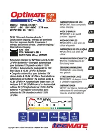
Electric vehicle charging device with 12V power supply, connected to a cable and terminal connector (no visible text or symbols on main body)| Battery voltage / Batteriespannung / Voltage de batterie / Accuspanning / Voltaje de la batería / Voltaggio della batteria | Output / Leistung / Sortie / Salida / Uitgang / Uscita / Utgang / Saida | |
| TM522 12V 2.5A max | ||
| TM523 12V 7A max | ||
MODEL : TM-522 Solar charge controller and battery monitor for 12V lead-acid batteries, for solar panels from 10–30W.
JN: 12V SOLAR PANEL 10-30W
OUT : DC output voltage : 12V ---
DC output current : 2.5A max.
MODEL : TM-523 Solar charge controller and battery monitor for 12V lead-acid batteries, for solar panels from 40–80W.
址: 12V SOLAR PANEL 40-84W
OUT : DC output voltage : 12V ---
DC output current : 7A max.

text_image
CHARGEDiscover our full range of accessories at optimize1.com