Ingenia IG3T - Speaker DB Technologies - Free user manual and instructions
Find the device manual for free Ingenia IG3T DB Technologies in PDF.
| Product type | Active 2-way loudspeaker with vertical directivity control |
| Dimensions (W x H x D) | 280 x 806 x 393 mm |
| Weight | 20.8 kg |
| Power supply | Auto-range 100-120 V~/220-240 V~, fuse T5A L 250V (220-240V) or T10A L 250V (100-120V) |
| RMS amplification power | 900 W (Class D, Digipro G3) |
| Peak power | 1800 W |
| Frequency response (-10 dB) | 53 - 20,000 Hz |
| Max SPL | 132 dB |
| Directivity (H x V) | 110° x 90° (+20°/-70°) |
| Crossover frequency | 1100 Hz |
| HF driver | 1.4" compression driver, neodymium magnet, 3" voice coil (titanium) |
| LF driver | 2 x 10", neodymium magnet, 2.5" voice coil |
| Internal processor | 56-bit DSP, A/D D/A conversion 24 bit/48 kHz |
| Main functions | Digital steering (beam control), EPD infrared communication, self-orienting OLED display, configuration menus, save/recall of 5 presets, password, high-pass and anti-feedback filter for microphone, system delay, stage alignment |
| Inputs | 1 combo XLR/Jack (balanced/unbalanced), LINE/MIC selector |
| Outputs | 1 XLR Link, 1 Mains Link (Neutrik powerCON TRUE1) |
| USB | Mini USB type B (for firmware update only) |
| Cabinet material | Reinforced polypropylene with internal metal structure, painted steel grille |
| Optional accessories | Fly-bar DRK-IG, brackets LP-IG, stand GSA-IG, bag TC-IG3T, protection RC-M1 |
| Safety and maintenance | Protect from moisture; do not open the amplifier; use only Neutrik cables; never suspend by the handles; replace the fuse according to voltage; for tripod mounting, max height 120 cm; for column mounting (2 units), use the LP-IG brackets |
Frequently Asked Questions - Ingenia IG3T DB Technologies
User questions about Ingenia IG3T DB Technologies
0 question about this device. Answer the ones you know or ask your own.
Ask a new question about this device
Download the instructions for your Speaker in PDF format for free! Find your manual Ingenia IG3T - DB Technologies and take your electronic device back in hand. On this page are published all the documents necessary for the use of your device. Ingenia IG3T by DB Technologies.
USER MANUAL Ingenia IG3T DB Technologies
natural_image
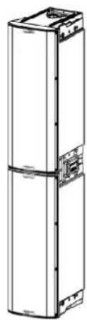
Technical line drawing of a multi-chamber electronic device with two circular components and mounting brackets (no text or symbols)USER MANUAL - Section 1
The warnings in this manual must be observed together with the "User Manual - Section 2".
According to the standards EN 55103 this equipment is designed and suitable to operate in E3 (or lower E2, E1) Electromagnetic environments.
FCC CLASS B STATEMENT ACCORDING TO TITLE 47, CHAPTER I, SUBCHAPTER A, PART 15, SUBPART B
This device complies with part 15 of the FCC Rules. Operation is subject to the following two conditions: (1) This device may not cause harmful interference, and (2) this device must accept any interference received, including interference that may cause undesired operation.
WARNING
Make sure that the loudspeaker is securely installed in a stable position to avoid any injuries or damages to persons or properties. For safety reasons di not place one loudspeaker on top of another without proper fastening systems. Before hanging the loudspeaker check all the components for damages, deformations, missing or damaged parts that may compromise safety during installation. If you use the loudspeakers outdoor avoid spots exposed to bad weather conditions.
Contact dBTechnologies for accessories to be used with the speakers. dBTechnologies will not accept any responsibility for damages caused by inappropriate accessories or additional devices.
INGENIA IG3T Cod. 420120239 REV. 1.1
ITALIANO
ENGLISH
DEUTSCH
FRANÇAIS
ESPAÑOL
INDICE
2. PRIMA ACCENSIONE.... 12
natural_image
Technical drawing of a rectangular frame with internal cutouts and dimension label (383), no readable text or symbols present.COPERTURA ACUSTICA
text_image
TA-IG truss adapter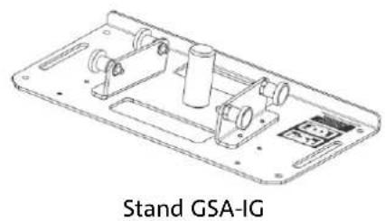
natural_image
Technical line drawing of a mechanical device with labeled 'Stand GSA-IG' at the bottom (no other text or symbols)
ATTENZIONE!
Stage Alignment Menu
IL MENU SYSTEM DELAY
natural_image
Diagram of a street scene with silhouetted figures and a light beam projecting onto a building facade (no text or symbols)Microphone Setting Menu
text_image
HP Filter 342Hz Antifefeedback 342HzINGENIA IG3T Cod. 420120239 REV. 1.1
IL MENU SYSTEM COVERAGE
IL MENU SUBWOOFER MATCHING
natural_image
Two identical stand-mounted devices with tripod legs, no text or symbols visible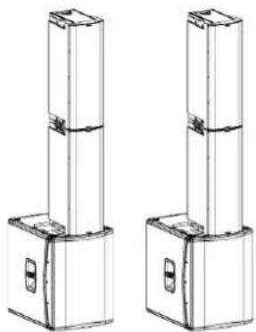
natural_image
Technical line drawing of two vertical cylindrical mechanical components with mounting flanges (no text or symbols)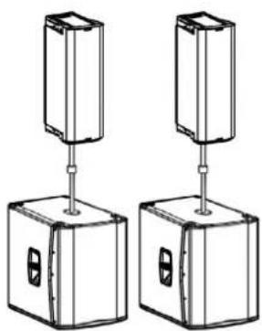
natural_image
Two identical rectangular electronic components with vertical connectors and base blocks, no text or symbols visible.INGENIA IG3T Cod. 420120239 REV. 1.1
natural_image
Two identical vertical structural columns with mounting feet, shown from different angles (no text or symbols)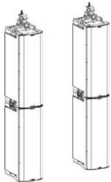
natural_image
Two identical cylindrical mechanical components with mounting flanges and side supports (no text or symbols visible)INGENIA IG3T Cod. 420120239 REV. 1.1
IL DIGITAL STEERING
natural_image
Illustration of a fire safety scene with silhouettes of people and a fire extinguisher emitting a beam (no text or symbols)Platea
SUBWOOFER MATCHING MENU 61
OPTIONS MENU....62
PASSWORD 62
CONTRAST....62
STAND-BY 62
RESTORE 62
INFO 62
EXIT 62
EXIT MENU....63
4. INSTALLATION EXAMPLES....64
INSTALLATION ON STAND....64
INGENIA IG3T Cod. 420120239 REV. 1.1
INDEX
INSTALLATION ON SUBWOOFER....64
INSTALLATION ON SUBWOOFER WITH POLE 64
FLOOR INSTALLATION 65
FLOWN INSTALLATION....65
DIGITAL STEERING....66
-
UPDATING THE FIRMWARE....67
-
TROUBLESHOOTING....68
-
TECHNICAL SPECIFICATIONS....70
GENERAL 70
ACOUSTIC DATA....70
AMPLIFIER....70
PROCESSOR....71
INPUTS....71
DIMENSIONS 71
INGENIA IG3T Cod. 420120239 REV. 1.1
1. GENERAL INFORMATIONS
WELCOME!
Thank you for purchasing a product designed and developed in Italy by dBTechnologies! This vertical 2-way active speaker is the result of years of experience and research on speakers, with the use of innovative solutions in the field of acoustics, electronics and research on materials.
PRELIMINARY OVERVIEW
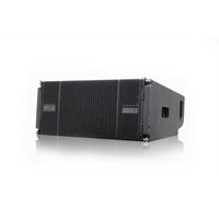
INGENIA IG3T is a vertical 2-way speaker, equipped with two 10" woofers and one 1.4" compression driver exit (voice coil: 3"), controlled by a latest generation 900 W RMS DIGIPRO G3 amplifier. Its most innovative characteristics include:
- an accurate design of the horn, featuring an asymmetric directivity, specifically designed to provide excellent acoustic coverage, ensuring an uncompromising sound definition in different indoor and outdoor applications.
- digital steering controlled by the powerful internal DSP, with the use of 2 stacked speakers, allowing to combine wider coverage and greater sound power with uncompromising accuracy and clarity.
- immediate automatic detection of the 2-speaker configuration, thanks to the infra-red communication system installed on the handles (EPD technology) and to the fast, customizable, DSP-controlled management. In this configuration the OLED displays orientate automatically. Just operating the control section of one of the two speakers allows to drive the whole system.
- an innovative shape, with the use of 2 woofers and 1 driver, in a cabinet combining ruggedness, sound performances, compactness and easy handling.
- extreme versatility, allowing to quickly and easily save and recall one's settings, protecting them with a settable password.
USER REFERENCES
To get the most from your INGENIA IG3T we recommend that you:
- thoroughly read the quick start user manual you will find in the package and this manual, and keep it throughout the product life.
- register the product on the site http://www.dbtechnologies.com, in the "SUPPORT" section.
- download and install the latest firmware from the Web site http://www.dbtechnologies.com, in the "DOWNLOADS" section (see chapter UPDATING THE FIRMWARE).
- keep the proof of purchase and the WARRANTY (User manual - section 2).
INGENIA IG3T Cod. 420120239 REV. 1.1
MECHANICAL AND ACOUSTIC CHARACTERISTICS
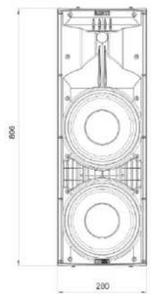
DIMENSIONS
INGENIA IG3T integrates, in a reinforced polypropylene cabinet weighing 20.8 kg (45.86 lbs), two 10" woofers and a one 1.4" compression driver exit (voice coil: 3") with neodymium magnets featuring exceptional compactness, weight and performances. Internally, a lightweight metal structure improves mechanical rigidity and acoustic behaviour. The dimensions of each individual speaker are: 280 x 806 x 393 mm (11.02 x 31.73 x 15.47 inches). The handles allow to easily transport it; the unit can be displaced by a single person. Different configurations are possible, e.g. mounting on subwoofer, possibility to suspend a single or double speaker.
text_image
806 280
natural_image
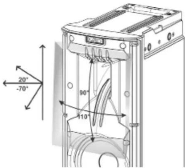
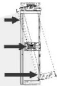
Technical line drawing of a rectangular frame with side markers and dimension label (360), no readable text or symbols present.ACOUSTIC COVERAGE
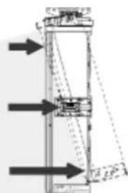
The special opening of the horn, outlined in the figure, ensures a total directivity of 110 × 90^ (+20^/-70^) . This asymmetric vertical directivity ensures excellent sound coverage, in indoor and outdoor contexts. Using 2 stacked IG3Ts, you can also control with the digital steering the full coverage of the speakers. This allows, even installing the IG3Ts vertically, to achieve the effect of a single inclined speaker, with all the ensuing benefits in terms of directivity.
text_image
20° -70° 90° 110°INGENIA IG3T Cod. 420120239 REV. 1.1
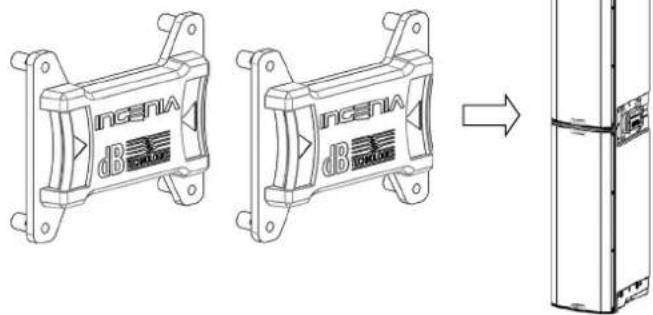
ACCESSORIES
The following optional accessories are available for quick installation:
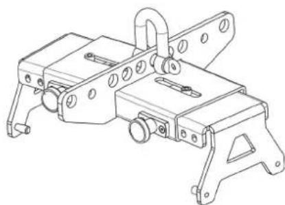
• Fly-bar DRK-IG (and the optional TA-IG) for vertical flown installation.
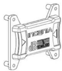
- LP-IG locking bracket pair allowing to fasten 2 stacked IG3T modules.
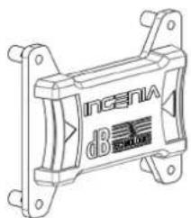
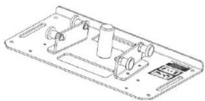
- Optional GSA-IG stand for installation on subwoofer (or on the floor).
- A specially designed bag (TC-IG3T) and a rain cover (RC-M1) are available for speaker transport and protection.
natural_image
Technical line drawing of a mechanical assembly with mounting brackets and mounting holes (no text or symbols)Fly Bar DRK-IG LP-IG Locking Bracket
text_image
ncsnv dB SARO
natural_image
Technical line drawing of a mechanical component with mounting flanges and a central label (no readable text or symbols)
natural_image
Line drawing of a tall refrigerator with front panels and side door (no text or symbols)
TA-IG truss adapter

natural_image
Technical line drawing of a mechanical assembly with no visible text or symbolsGSA-IG stand

WARNING!
- Never use the handles to suspend the speaker!
For further information please refer to the relevant manuals.
INGENIA IG3T Cod. 420120239 REV. 1.1
CHARACTERISTICS OF THE AMPLIFICATION AND CONTROL SECTION
The D-class latest generation digital amplifier DIGIPRO G3 is the core of IG3T and can provide a sound power of 900 W RMS. Thanks to a switching power supply section featuring a particularly efficient auto-range function, the system is quiet, as it requires no active cooling system. The system is controlled by a powerful DSP, allowing to define different parameters, as well as to automatically manage the communication between the modules, in case of configuration with 2 stacked speakers. In the latter case, the DSP individually controls the acoustic components, to obtain a configurable directional sound focus (digital steering).

ATTENTION!
- Protect the module from humidity.
- Never try to open the amplifier.
- In case of malfunction, immediately cut off the power supply, by disconnecting the module from the mains, then contact an authorised repairman.
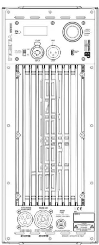
The DIGIPRO G3 panel consists of:
- INPUT AND CONTROL SECTION
- AMPLIFIER
• POWER SUPPLY SECTION
INGENIA IG3T Cod. 420120239 REV. 1.1
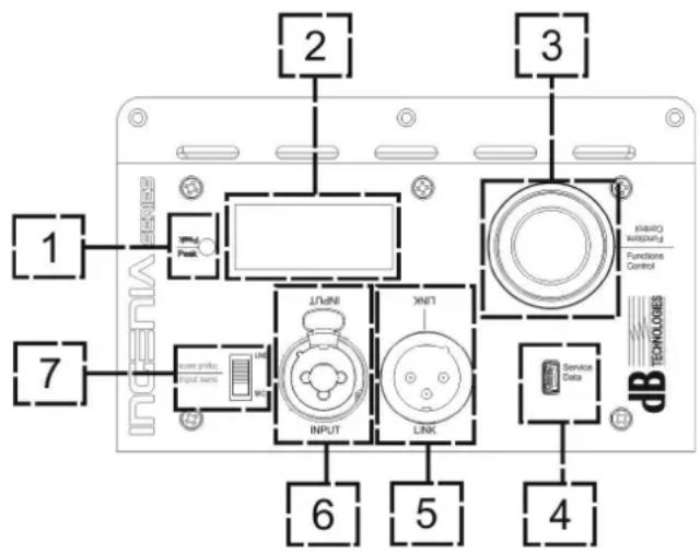
INPUT AND CONTROL SECTION
1. "PEAK" LED
Red LED that lights up briefly when connecting power or in case of audio limiter operation.

ATTENTION!
Never use the speaker for a prolonged time while the limiter LED is on or blinking, indicating the equipment is running under excessive stress conditions with distorted sound.
text_image
1 2 3 7 6 5 4 Service Data TECHNOLOGIES INPUT LINK INLOT INLOT INLOT INLOT INLOT INLOT INLOT INLOT INLOT INLOT INLOT INLOT INLOT INLOT INLOT INLOT INLOT INLOT INLOT INLOT INLOT INLOT INLOT INLOT INLOT INLOT INLOT INLOT INLOT INLOT INLOT INLOT INLOT INLOT2. OLED DISPLAY
The display automatically orientates according to the
accelerometer control, detecting whether the speaker has been installed
straight vertically or flipped. The user can configure a contrast adjustment and automatic power-off function (see chapter CONTROL PANEL AND SETTING MENUS).
3. PUSH ROTARY ENCODER
The push rotary encoder allows both a rotary selection (selection of menus and values), and a push selection (selection confirmation) to navigate the menus.
4. USB SERVICE DATA
The type B mini-USB B port allows to update the product firmware. For further information, please refer to the Web site http://www.dbtechnologies.com in the "DOWNLOADS" section and to chapter UPDATING THE FIRMWARE)

ATTENTION!
The USB SERVICE DATA connection must only be used to update the product firmware; never connect any USB device to the equipment, to avoid possible damages or malfunctions.
5. "LINK" OUTPUT
Balanced "XLR" output, allowing to send the input audio signal to another amplified speaker.
6. "INPUT" COMBO INPUT
Combined XLR-TR-TRS audio signal input. It allows to use a balanced XLR connector, or a 14 " TS or TRS jack input.

ATTENTION!
Only use cables equipped with high-quality Neutrik ^® original connectors. Using different or poor-quality connectors might affect the speaker operation.
7. "INPUT SENSITIVITY" SELECTOR
A selector allowing to set whether the incoming signal comes from a mixer/a line (“LINE”) or from a microphone (“MIC”).
INGENIA IG3T Cod. 420120239 REV. 1.1
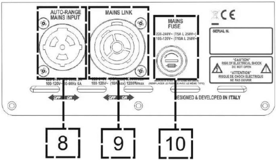
POWER SUPPLY SECTION
text_image
AUTO-RANGE MAINS INPUT MAINS LINK MAINS FUSE 220-240V~ (T5A L 250V~ 100-120V~ (T10A L 250V~ SERIAL N. "CAUTION" RISK OF ELECTRICAL SHOCK DO NOT OPEN "ATTENTION" RISQUE DE CHOCH ELECTRIQUE NE PAS OUVIRER DESIGNED & DEVELOPED IN ITALY 8 9 10- "AUTO-RANGE MAINS INPUT" POWER SUPPLY INPUT
Input for Neutrik® powerCON TRUE1 connector.
- "MAINS LINK" POWER SUPPLY LINKING OUTPUT
The connection provided by Neutrik® NAC3PX allows to link the power supply to a second module.
- "MAINS FUSE" PROTECTION FUSE
Mains fuse

ATTENTION!
The speaker is supplied equipped with a pre-installed fuse designed to operate within the 220-240 V range. If the system must operate within the 100-120 V range:
- Disconnect all connections, including the power supply one
- Wait 5 minutes.
- Replace the fuse with the one included in the package for the 100-120 V range.
- Only use the provided power cord.
INGENIA IG3T Cod. 420120239 REV. 1.1
2. FIRST SWITCH-ON
PACKAGE CONTENTS
Open the package and check that the INGENIA IG3T speaker packaging contains all the items included in the supply. The packaging includes:
- power cord with connector Neutrik® TRUE powerCON TRUE1®
- INGENIA IG3T
- quick start and warranty-related documents
- fuse to be installed if the system is to operate within the 100-120V range

ATTENTION!
The speaker is supplied equipped with a pre-installed fuse designed to operate within the 220-240 V range. If the system must operate within the 100-120 V range:
- Disconnect all connections, including the power supply one
- Wait 5 minutes.
- Replace the fuse with the one included in the package for the 100-120 V range.
- Only use the provided power cord.
INSTALLATION
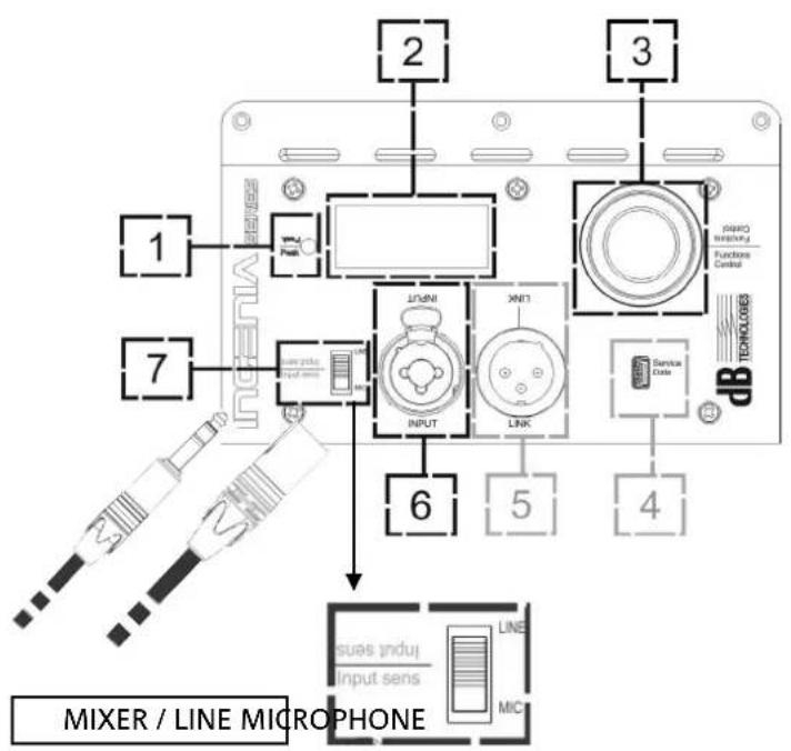
CONNECTING THE INPUTS
text_image
MIXER / LINE MICROPHONE 1 2 3 4 5 6 7 LINK INPUT XNT1 LINE MIC Service Data TECHNOLOGES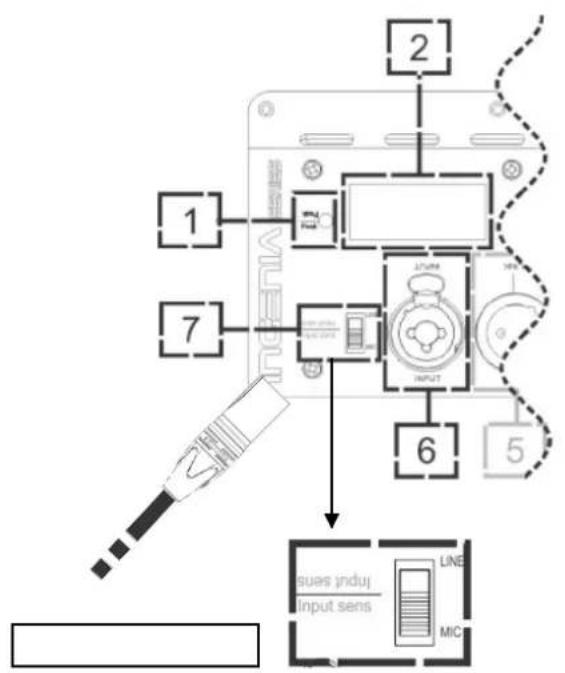
text_image
1 2 7 6 5 issues induj Input sens LINE MICINGENIA IG3T Cod. 420120239 REV. 1.1
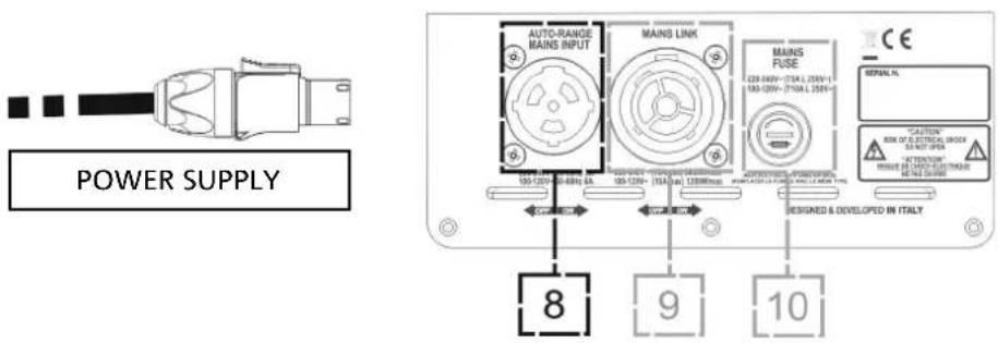
CONNECTING THE POWER SUPPLY
text_image
POWER SUPPLY AUTO-RANGE MAINS INPUT MAINS LINK MAINS FUSE 120-400V - 270A L 250V-1 150-120V - 270A L 250V- RESIGNED & DEVELOPED IN ITALY 8 9 10 C#P #R C#P #L C#P #L C#P #L C#P #L C#P #L C#P #L C#P #L C#P #L C#P #L C#P #L C#P #L C#P #L C#P #L C#P #L C#P #L C#P #L C#P #L C#S C# C# C# C# C# C# C# C# C# C# C# C# C# C# C# C# C# C# C# C# C# C# C# C# C# C# C# C# C# C# C# C# C# C# C# C# C# C# C# C# C# C# C# C# C# C# C# C# C# C# C#\N##N R#K OF S ETTREAL GROCK SA NOT OPEN MISSE DE PRACTOCTRUS REVE CABBAGE
ATTENTION!
Only use cables equipped with high-quality Neutrik® original connectors. Replace any damaged cables, to avoid malfunctions and poor sound quality.
To properly install the INGENIA IG3T speaker:
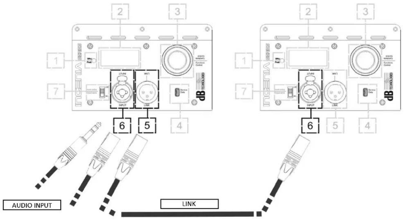
- Properly connect the audio input (6), using the "INPUT SENSITIVITY" (7) selector to set the source. If the input signal comes from a line or from a mixer output set the selector (7) to "LINE"; if the input signal comes from a microphone (use a dynamic microphone), set the selector (7) to "MIC". For a brief overview of audio cables please refer to the table at page 49.
- Connect the power supply, connecting the cable equipped with Neutrik® TRUE powerCON TRUE1® connector to "MAINS INPUT" (8)
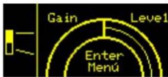
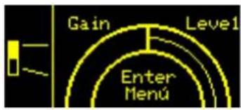
- At switch-on the peak LED blinks briefly and the OLED screen (2) activates, displaying the initial level and gain control screen:
text_image
Gain Level1 Enter Menú- Turn the PUSH ROTARY ENCODER (3) to the left or to the right to adjust the system gain to an appropriate level.
- Verify the correct sound emission of IG3T.
INGENIA IG3T Cod. 420120239 REV. 1.1
• Balanced


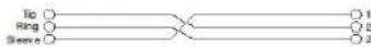
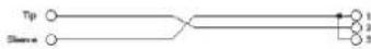
- Unbalanced


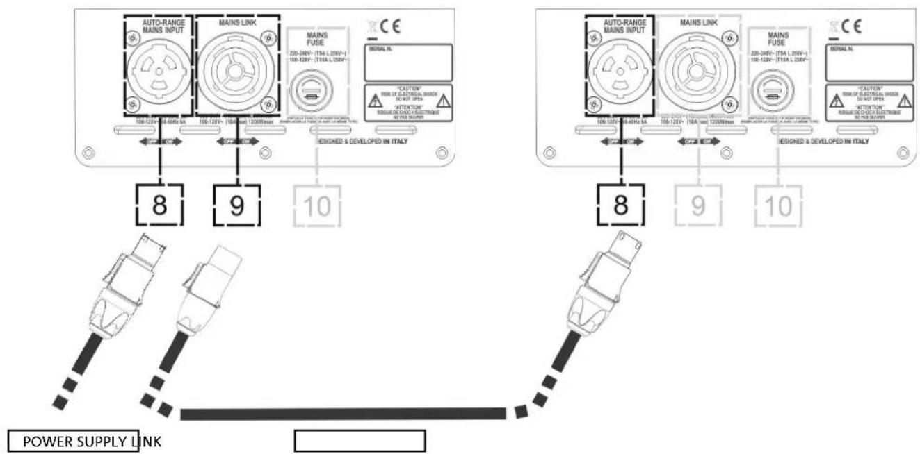
CONNECTING OUTPUTS BETWEEN MULTIPLE MODULES (power supply linking)

NOTE FOR THE INSTALLER (100-120V). The nameplate data on the speaker panel refer to (and are limited to) the cable provided. If you do not use the supplied cable, the maximum allowed limits of currents (and powers) of LINK are indicated in the following table:
| Model Current (100-120 V) Powers (100-120 V) | |
| IG3T (100-120 V) 14 A 1600 W |
The cables must be properly sized and design, installation and system testing should be performed exclusively by qualified personnel. A.E.B. Industriale accepts no responsibility in case of use of cables which are unsuitable, non-certified, non-compatible with the correct system sizing and the regulations in force in the country of use.
text_image
AUTO-RANGE MAINS INPUT MAINS LINK MAINS FUSE 220-240V~ (TSA L 200V~) 100-120V~ (TSA L 200V~) DESIGNED & DEVELOPED IN ITALY 8 9 10 AUTO-RANGE MAINS INPUT MAINS LINK MAINS FUSE 220-240V~ (TSA L 200V~) 100-120V~ (TSA L 200V~) DESIGNED & DEVELOPED IN ITALY 8 9 10 POWER SUPPLY LINKINGENIA IG3T Cod. 420120239 REV. 1.1
The use of Neutrik® PowerCON TRUE1® connectors on IG3T allows to link the power supply of the first speaker with a subsequent one, up to a maximum current of 13 A (3000 W) for the countries where voltage is 220-240Vac, and of 10 A (1200 W), for the countries where voltage is 100-120Vac. To make this type of connection, simply plug the power cord supplied to the MAINS INPUT (8) of the first IG3T and connect the cable LINK powerCON TRUE1® (optional) between the MAIN LINK output (9) and the MAINS INPUT (8) of the next IG3T. It is possible to repeat this type of connection until it is achieved the maximum allowed current as indicated by the MAINS LINK connector (9) of the first speaker.

CAUTION!
The maximum allowed current indicated on the rating plate of IG3T (MAIN LINK) is calculated from the specification of the maximum current of the PowerCON TRUE1® connector; this value is not absolute but depends on the type of cable used for the connection to the power grid of the first IG3T (section and type of plug used) and on the subsequent LINK cables (section and type of cable). Always check during the design and sizing stage of the system and before making any connections in series among the products, the maximum allowable currents (and powers) and the exact sizing of the sections of the cables used.
CONNECTING OUTPUTS BETWEEN MULTIPLE MODULES (audio signal linking)
text_image
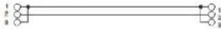
2 3 1 7 INGENIA INPUT LINK 6 5 4 AUDIO INPUT LINK 2 3 1 7 INGENIA INPUT LINK 6 5 4 AUDIO INPUT LINKTo connect 2 or more speakers to the same audio source, it may be useful, in some installation configurations, to link the signal from the first one to a second one and so on. First of all connect a sound source of any type to the "INPUT" input (6) of the first speaker (for the "LINE" or "MIC" connection, which is different, please refer to section CONNECTING THE INPUTS). Using a balanced XLR cable, then, connect the "LINK" output (5) of the first speaker to the "INPUT" input (6) of the second one. This second operation can then be repeated to connect other speakers, to get the installation layout that is the most appropriate for the context.
INGENIA IG3T Cod. 420120239 REV. 1.1
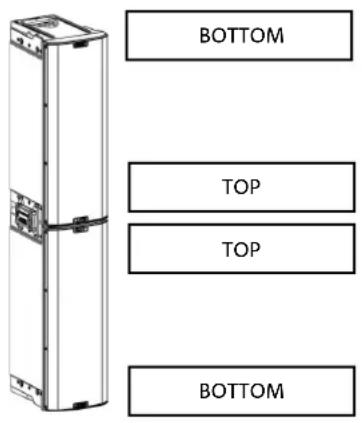
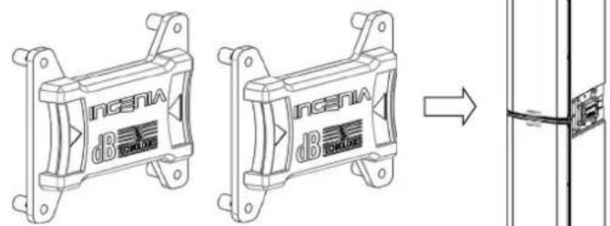
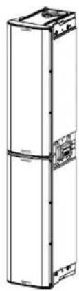
USE OF A PAIR OF STACKED IG3T SPEAKERS
To properly couple and then use two stacked IG3T speakers, you need a pair of LP-IG connecting brackets. For further details please refer to the instructions of this accessory.
Once the two speakers are properly mounted, the infra-red detection system installed on the handles activates automatically; the user will just have to run the check in the initial configuration menus, that will be discussed in the next chapter.

ATTENTION!
- Only 2 identical speakers can be installed, interconnected and detected through the infra-red ports.
- Never use the handles to suspend the speaker!
text_image
BOTTOM TOP TOP BOTTOM3. CONTROL PANEL AND SETTING MENUS
ACCESSING THE MENUS
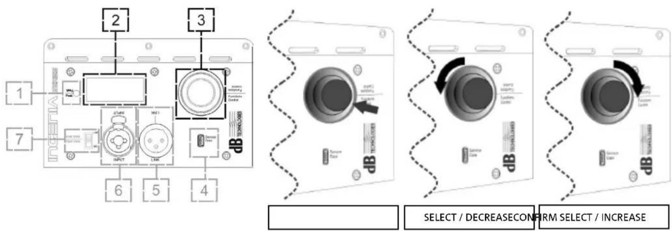
The push rotary encoder (3) allows the user both to perform a selection by turning it and to confirm a selection by pressing it. These operations allow to navigate the menus and sub-menus available on the OLED display (2). Inside the menus and sub-menus, turning the encoder to the right or to the left also allows to increase or decrease the selected values.
text_image
1 7 2 3 INPUT INPUT1 LINK INTERS Pulsifier Control DB TECHNOLOGY 6 5 4 SELECT / DECREASE CONFIRM SELECT / INCREASEPush rotary encoder use examples
The initial screen at switch-off displays the IG3T level and gain. All settings can be protected by a password.

- Once manually performed, the settings remain stored even after the speaker has been switched off.
- After approximately one minute has elapsed since the last selection or confirmation, the system returns to the initial screen (IG3T level/gain). The user can also return to the initial screen from any point, in 2 ways:
a. by selecting and confirming, when existing in a sub-menu, the symbol b. by holding the push rotary encoder pressed for a few seconds

- If the speakers are 2 and installed in a stacked configuration, the system detects them and automatically assigns the control of both to the amplifier which is being operated. This allows to perform an adjustment that will apply and can be stored for the whole system, irrespective of the rotary that is being operated (mirroring OLED).
At switch-on, the IG3T display shows the initial screen, indicating the GAIN and the signal level, simulating a VU METER.
INGENIA IG3T Cod. 420120239 REV. 1.1
text_image
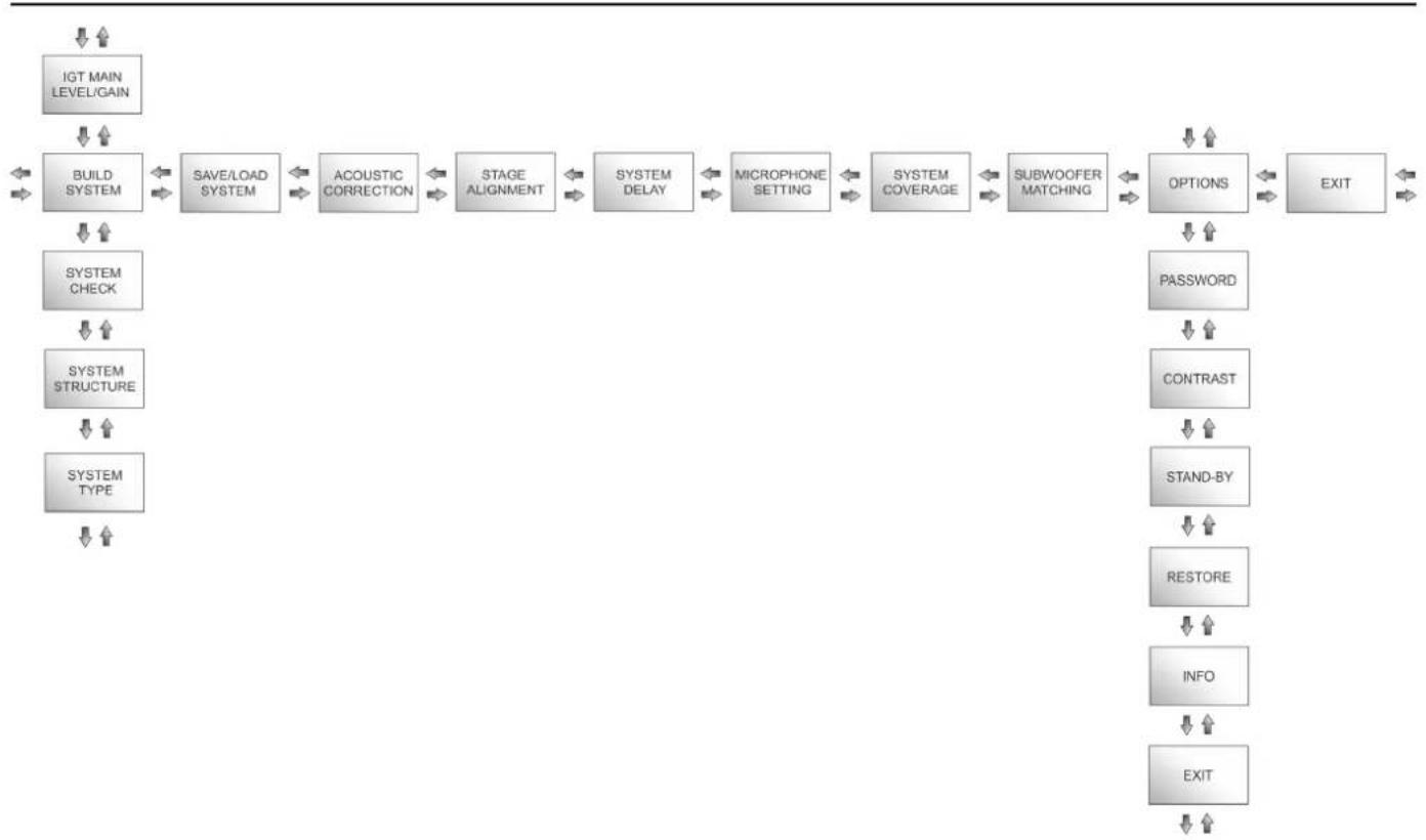
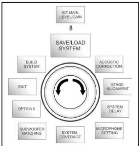
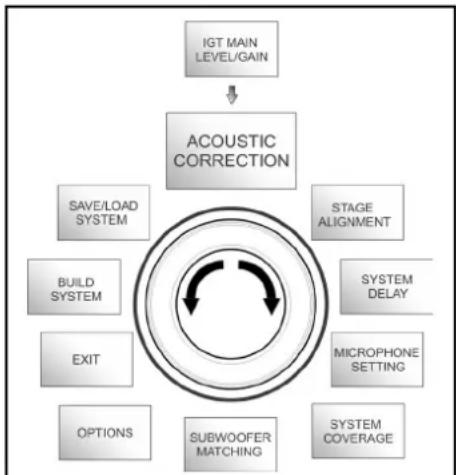
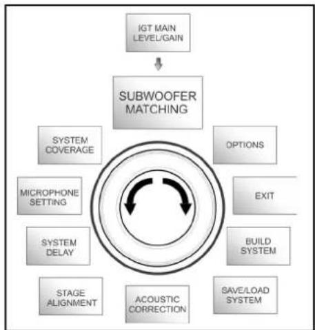
Gain Level1 Enter MenúFrom this screen, pressing the rotary push encoder allows to access the different menus, whose general structure is shown in the figure.
flowchart
graph TD
    A["IGT MAIN LEVEL/GAIN"] --> B["BUILD SYSTEM"]
    B --> C["SAVE/LOAD SYSTEM"]
    C --> D["ACOUSTIC CORRECTION"]
    D --> E["STAGE ALIGNMENT"]
    E --> F["SYSTEM DELAY"]
    F --> G["MICROPHONE SETTING"]
    G --> H["SYSTEM COVERAGE"]
    H --> I["SUBWOOFER MATCHING"]
    I --> J["OPTIONS"]
    J --> K["EXIT"]
    L["SYSTEM CHECK"] --> M["SYSTEM STRUCTURE"]
    M --> N["SYSTEM TYPE"]
    O["PASSWORD"] --> P["CONTRAST"]
    Q["TRANSFORM"] --> R["STAND-BY"]
    S["RESTORE"] --> T["INFO"]
    U["EXIT"] --> V["EXIT"]
The Structure of Menus

ATTENTION!
- The "SYSTEM COVERAGE" menu is only displayed when the menu has automatically detected, through the infra-red ports installed on the handles, that there are 2 stacked speakers, properly installed.
- The "SUBWOOFER MATCHING" menu is only displayed when the presence of a subwoofer has been selected in the settings, otherwise it shall not be displayed, as it is unnecessary to the user.
INGENIA IG3T Cod. 420120239 REV. 1.1
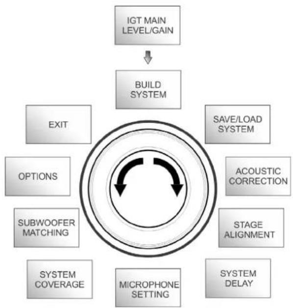
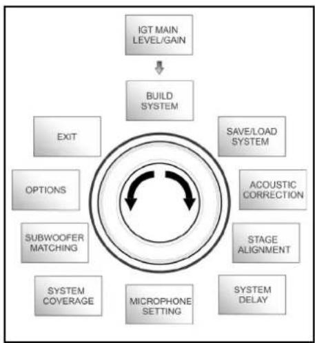
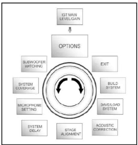
The main menu structure can be represented in a circular form, as the push rotary encoder allows to browse the menus by rotating it both to the left and to the right.
flowchart
graph TD
    A["IGT MAIN LEVEL/GAIN"] --> B["BUILD SYSTEM"]
    B --> C["EXIT"]
    B --> D["SOPTIONS"]
    B --> E["SUBWOOFER MATCHING"]
    B --> F["SYSTEM COVERAGE"]
    B --> G["MICROPHONE SETTING"]
    B --> H["SYSTEM DELAY"]
    B --> I["STAGE ALIGNMENT"]
    B --> J["ACOUSTIC CORRECTION"]
    B --> K["SAVE/LOAD SYSTEM"]
Circular form representation
INGENIA IG3T Cod. 420120239 REV. 1.1
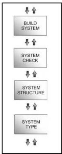
BUILD SYSTEM MENU
This menu automatically configures the system according to the number of speakers, to the presence or absence of a subwoofer, as well as to the location and inclination of the speakers. It consists of 3 sub-menus:
- SYSTEM CHECK
- SYSTEM STRUCTURE
- SYSTEM TYPE
flowchart
graph TD
    A["IGT MAIN LEVEL/GAIN"] --> B["BUILD SYSTEM"]
    B --> C["EXIT"]
    B --> D["SOFTS"]
    B --> E["SUBWOOFER MATCHING"]
    B --> F["SYSTEM COVERAGE"]
    B --> G["MICROPHONE SETTING"]
    B --> H["SYSTEM DELAY"]
    B --> I["STAGE ALIGNMENT"]
    B --> J["ACOUSTIC CORRECTION"]
    B --> K["SAVE/LOAD SYSTEM"]
Build System Menu
flowchart
graph TD
    A["BUILD SYSTEM"] --> B["SYSTEM CHECK"]
    B --> C["SYSTEM STRUCTURE"]
    C --> D["SYSTEM TYPE"]
Sub-menus
SYSTEM CHECK
The system can detect, through infra-red communication (the communication ports are installed on the speaker handles and detection is automatic) whether the user is using one or two IG3T speakers. After accessing this screen:
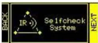
text_image
IR Selfcheck System BACK NEXT- Turn the rotary encoder selecting → Selfcheck System, then confirm the choice by pressing the push rotary encoder.
- After a short animation, the system automatically switches to the next menu (SYSTEM STRUCTURE).
- If this operation doesn't need to be performed, select and confirm → NEXT; if you need to return to the main screen, select and confirm → BACK
SYSTEM STRUCTURE
The menu allows to manually update the configuration of the system in use, adding or removing one or more subwoofers. If you need to update the number of connected subwoofers:
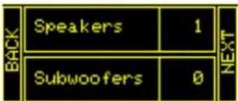
text_image
BACK Speakers 1 Subwoofers 0 NEXT- turn the rotary encoder, select the "subwoofer" item and confirm it
- select and confirm the number of subwoofers you want to use
- select and confirm → NEXT to switch to the next menu; select and confirm → BACK to return to the SYSTEM CHECK sub-menu
INGENIA IG3T Cod. 420120239 REV. 1.1
SYSTEM TYPE
The system types available when using the IG3T are 2:
- Stacked
- Flown
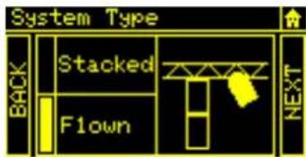
text_image
System Type BACK Stacked T Flown NEXTIn the “Stacked” configuration an IG3T speaker rests on a stand, or one or 2 speakers rest on a subwoofer (see chapter INSTALLATION EXAMPLES); in the “Flown” configuration, instead, one or two IG3T speakers are hanging. After accessing the SYSTEM TYPE menu, then:
- Select and confirm the desired mode, choosing between “Stacked” and “Flown”; select and confirm → NEXT to access the next screen (select and confirm → BACK to return to the previous one). Now, if the system has previously detected the presence of 2 speakers, it will switch to the SYSTEM COVERAGE menu, and if the presence of a woofer has been selected in the previous SYSTEM STRUCTURE sub-menu, it will then switch to the SUBWOOFER MATCHING menu; should that not be the case (Speakers 1, Subwoofer 0) the next screen will be the initial one, and the procedure will end.

ATTENTION!
- Never install the speaker directly resting on the ground, but always use the optional GSA-IG.
- When "Stacked" on a tripod stand, the INGENIA IG3T cannot be mounted in the configuration with 2 speakers stacked, but only in a single speaker configuration, for safety reasons.
SAVE/LOAD SYSTEM MENU
This menu allows to save and then recall the system usage configurations. Even though at switch-off the IG3T retains all the information about the latest settings, it may be useful to have at one's disposal, for different contexts, a previously saved batch of appropriate settings, and to be able to quickly reload them. To this purpose, IG3T allows to save and rename 5 batches of settings, using the "SAVE" function, and to recall them using the "RECALL" function. Should you later have to edit the settings stored in one of the memory slots, you can later overwrite the previously saved slots.
flowchart
graph TD
    A["IGT MAIN LEVEL/GAIN"] --> B["SAVE/LOAD SYSTEM"]
    B --> C["BUILD SYSTEM"]
    B --> D["EXIT"]
    B --> E["OPTIONS"]
    B --> F["SUBWOOFER MATCHING"]
    B --> G["SYSTEM COVERAGE"]
    B --> H["ACOUSTIC CORRECTION"]
    B --> I["STAGE ALIGNMENT"]
    B --> J["SYSTEM DELAY"]
    B --> K["MICROPHONE SETTING"]
Save/Load System Menu
INGENIA IG3T Cod. 420120239 REV. 1.1
To save a batch of settings, after setting the different parameters in the other menus, access the SAVE/LOAD SYSTEM menu and:
- Select and confirm the number of one of the memory slots, from 1 to 5,
-
Select and confirm "SAVE".
-
Assign a title to the slot. You can only use an alphanumeric title consisting of up to 14 letters/digits. Select and confirm one letter at a time next to the slot number. To end the title just confirm (without selecting) the blank space character (_).
-
Press "OK" at the next screen
-
The system then saves the settings in the slot number with the chosen title
To recall a batch of settings, loading it into the system:
- Select and confirm the desired memory slot
- Select and confirm "RECALL".
- Press "OK" at the next screen
- The system has loaded the settings associated with the desired memory slot and has returned to the main screen
To overwrite a previous batch of settings with a new one just select a pre-existing slot, then select and confirm "OK" in the overwrite confirmation screen.
ACOUSTIC CORRECTION MENU
In various cases it may be useful to perform a differentiated equalisation of the speaker output signal. The DSP installed in the IG3T also manages this option.
To this purpose access the ACOUSTIC CORRECTION menu and:
- Select and confirm the frequency band to which the correction must be applied. You can operate on 3 bands:
A. LF - Low Frequency, with +3dB - 6 dB correction and 0.5 dB resolution
B. MF - Medium Frequency, with +0 dB - 6 dB correction and 0.5 dB resolution
C. HF - High Frequency, with +3 dB - 6dB and 0.5 dB resolution
- Select and confirm the desired correction level
- If the operation needs to be repeated for other bands return to point 1., otherwise select the home symbol and return to the main menu selection
flowchart
graph TD
    A["IGT MAIN LEVEL/GAIN"] --> B["ACOUSTIC CORRECTION"]
    B --> C["SAVE/LOAD SYSTEM"]
    B --> D["BUILD SYSTEM"]
    B --> E["EXIT"]
    B --> F["OPTIONS"]
    B --> G["SUBWOOFER MATCHING"]
    B --> H["STAGE ALIGNMENT"]
    B --> I["SYSTEM DELAY"]
    B --> J["MICROPHONE SETTING"]
    B --> K["SYSTEM COVERAGE"]
Acoustic Correction Menu
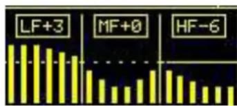
text_image
LF+3 MF+0 HF-6
- The acoustic correction can be used to improve intelligibility or attenuate frequencies which are predominant. It does not replace a proper speaker arrangement, which must be assessed taking into account the acoustic characteristics of the room or of the outdoor environment.
INGENIA IG3T Cod. 420120239 REV. 1.1
STAGE ALIGNMENT MENU
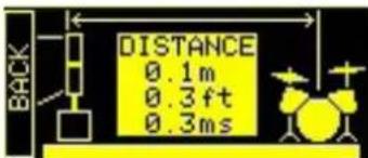
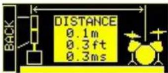
In a live scenario with different sources of amplification, like guitar amplifiers on the stage, or natural sound sources like a battery, you can virtually “align” the IG3T speakers, specifying the distance of the sources in question, in metres or feet. This will allow to obtain a single acoustic wavefront without any delays, in all the live scenarios where this is required. The DSP will automatically delay the IG3T signal output, increasing the performance effectiveness. To this purpose, after accessing the STAGE ALIGNMENT menu:
- Select and confirm the "DISTANCE" field
- Select and confirm the desired distance value, with a range of 0-15 m and a resolution of 20 cm.
- Return to the initial screen by selecting the "HOME" symbol
Stage Alignment Menu
SYSTEM DELAY MENU
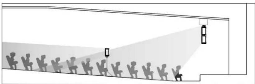
If the IG3T speakers are used in environments requiring multiple amplification stages replicated at different distances - for example when they need to cover a particularly wide and long indoor environment, with various sound obstacles, the signal output by the speaker can be appropriately delayed, to ensure that the listener only perceives a single apparent wavefront, at any point in the room. In this case an equivalent setting in terms of time/distance can be useful.
To this purpose, after accessing the SYSTEM DELAY menu:
- Select and confirm the "DELAY" field
- Select and confirm the desired delay value, with a range of 0-126 ms in terms of time or of 0-43.7 m / 0-143.4 ft (feet) in terms of distance
- Return to the initial screen by selecting the "HOME" symbol
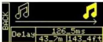
text_image
BACK Delay 126_5ms 43_7m 143_4ft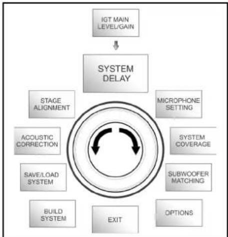
flowchart
graph TD
    A["IGT MAIN LEVEL/GAIN"] --> B["SYSTEM DELAY"]
    B --> C["STAGE ALIGNMENT"]
    B --> D["MICROPHONE SETTING"]
    B --> E["SYSTEM COVERAGE"]
    B --> F["SUBWOOFER MATCHING"]
    B --> G["ACOUSTIC CORRECTION"]
    B --> H["SAVE/LOAD SYSTEM"]
    B --> I["BUILD SYSTEM"]
    B --> J["EXIT"]
    B --> K["OPTIONS"]
System Delay Menu
INGENIA IG3T Cod. 420120239 REV. 1.1
natural_image
Diagram of a street scene with silhouetted figures and a light beam projecting onto a building facade (no text or symbols)Wide indoor environment setting
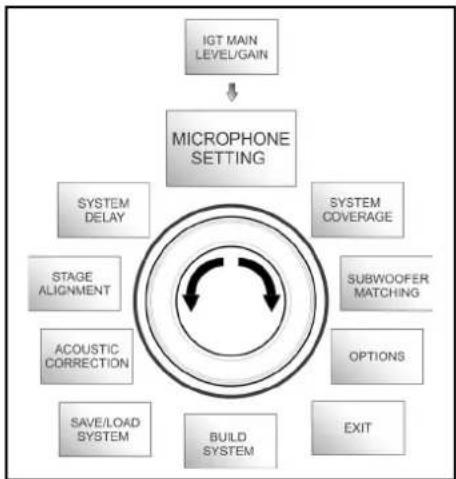
MICROPHONE SETTING MENU
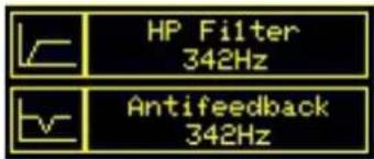
IG3T allows the input of a microphone with XLR connector. When using this source, it may be useful to apply a filtering to the signal to cut any unwanted frequencies (by a high-pass filter with adjustable cut frequency). Or it may be necessary to intervene (by a notch or band-stop filter with selectable band centre) to prevent any feedback (or Larsen effect). To perform one of these settings, or both of them, after accessing the MICROPHONE SETTING menu:
- Select and confirm HP filter (high-pass filter)
- Select and confirm the value of the high-pass filter cut frequency, with a range of 50 Hz – 200 Hz and a resolution of 10 Hz (select the "None" value if you wish to disable the filter)
- Select and confirm "Antifeedback" (anti-feedback or anti-Larsen effect filter)
- Select and confirm the value of the band centre frequency, with a range of 260 Hz – 15000 Hz and a resolution of 10 Hz (select the "None" value if you wish to disable the filter)
- Return to the initial screen by selecting the "HOME" symbol
flowchart
graph TD
    A["IGT MAIN LEVEL/GAIN"] --> B["MICROPHONE SETTING"]
    B --> C["SYSTEM DELAY"]
    B --> D["SYSTEM COVERAGE"]
    B --> E["SUBWOOFER MATCHING"]
    B --> F["OPTIONS"]
    B --> G["EXIT"]
    B --> H["BUILD SYSTEM"]
    B --> I["SAVE/LOAD SYSTEM"]
    B --> J["ACOUSTIC CORRECTION"]
    B --> K["STAGE ALIGNMENT"]
Microphone Setting Menu

text_image
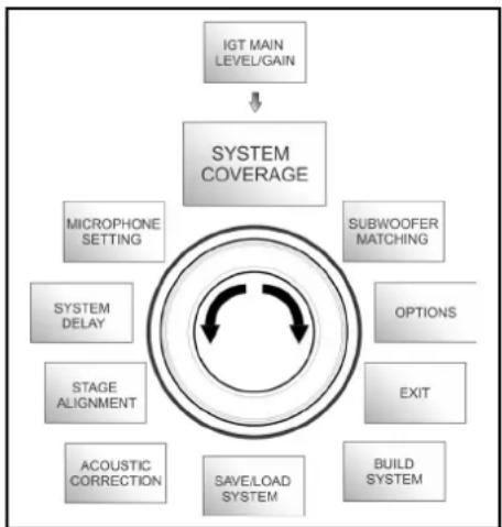
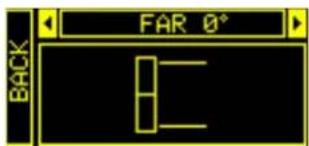
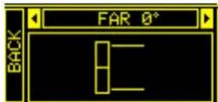
HP Filter 342Hz Antifefeedback 342HzSYSTEM COVERAGE MENU
For information about the functions contained in this menu, only displayed if during SYSTEM CHECK the system has automatically detected 2 speakers, also refer to paragraph “DIGITAL STEERING” in the “INSTALLATION EXAMPLES” section. This menu allows to modify the beam of the emitted wave and the relevant acoustic coverage when the system has detected 2 speakers properly installed in a stacked configuration and properly recognised by the DSP, on the basis of pre-sets already stored that can be selected and then confirmed:
- UP 10^ for an installation requiring an acoustic coverage from the bottom up, with mounting on stand or subwoofer and with as much inclination as possible.
- UP →+5° to orientate the wavefront with a medium upward inclination, with mounting on stand or subwoofer
- UP 2.5° to get an acoustic coverage with a slight upward inclination.
- FAR 0^ when you want a coverage getting as far as possible, when speakers are installed in front of the auditorium, at the height of the audience.
- DOWN 2.5^ to be used to orientate the acoustic coverage slightly downward (for example with the public not very far from the speakers and flown installation).
- DOWN 5^ for a directivity with a medium downward inclination (for example with public close to the speakers and flown installation).
- DOWN 10^ to incline the acoustic coverage as downward as possible (public very close to the speakers and flown installation).
flowchart
graph TD
    A["IGT MAIN LEVEL/GAIN"] --> B["SYSTEM COVERAGE"]
    B --> C["MICROPHONE SETTING"]
    B --> D["SUBWOOFER MATCHING"]
    B --> E["OPTIONS"]
    B --> F["EXIT"]
    B --> G["BUILD SYSTEM"]
    B --> H["SAVE/LOAD SYSTEM"]
    B --> I["ACOUSTIC CORRECTION"]
    B --> J["STAGE ALIGNMENT"]
    B --> K["SYSTEM DELAY"]
System Coverage Menu
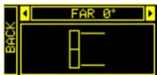
text_image
FAR 0° BACKINGENIA IG3T Cod. 420120239 REV. 1.1
SUBWOOFER MATCHING MENU
This menu is only displayed if the presence of at least one subwoofer has previously been selected, in the BUILD SYSTEM→SYSTEM STRUCTURE sub-menu. In addition, in this case, this menu is accessed automatically after the "SYSTEM TYPE" settings have been performed, to complete the general system settings. First of all, the menu allows to identify the subwoofer in use, then to decide whether to use its crossover frequency or to set a frequency depending on the model (maximum range 70-120 Hz with a resolution of 5 Hz). This choice depends on the type of subwoofer-speaker connection, as shown in the figure below. The menu also suggests the delay to be set in the subwoofer. To choose the crossover frequency, after accessing the SUBWOOFER MATCHING menu:
flowchart
graph TD
    A["IGT MAIN LEVEL/GAIN"] --> B["SUBWOOFER MATCHING"]
    B --> C["SYSTEM COVERAGE"]
    B --> D["OPTIONS"]
    B --> E["MICROPHONE SETTING"]
    B --> F["SYSTEM DELAY"]
    B --> G["STAGE ALIGNMENT"]
    B --> H["ACOUSTIC CORRECTION"]
    B --> I["BUILD SYSTEM"]
    B --> J["SAVE/LOAD SYSTEM"]
    B --> K["EXIT"]
Subwoofer Matching Menu
- Select and confirm the type of associated subwoofer in the system
- Select and confirm HpFilter, then select and confirm the desired crossover frequency
- According to the system settings, verify the delay value recommended for the subwoofer in the SubDelay field
- Select "BACK" or "HOME" to respectively return to the menu selection or to the main screen
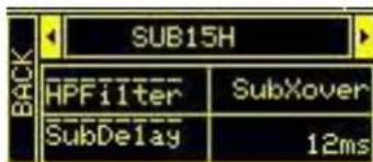
text_image
BACK SUB15H HPFilter SubXover SubDelay 12ms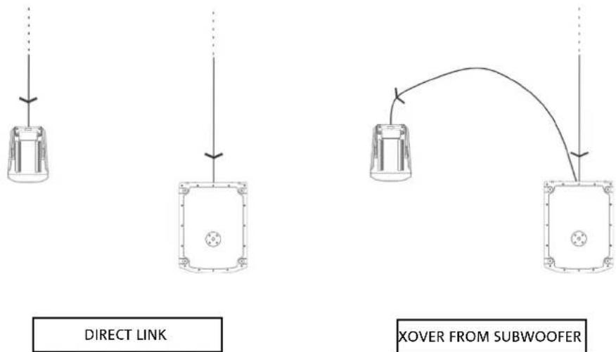

If necessary, you can directly set a value of HpFilter on IG3T, without using the crossover of a subwoofer. If instead you use the latter:
a) in the case of DIRECT CONNECTION, check the subwoofer crossover frequency, and replicate it on IG3T by setting its value in the HpFilter field.
b) In case of connection XOVER FROM THE SUBWOOFER, set "SubXover" in the field HpFilter of IG3T.
INGENIA IG3T Cod. 420120239 REV. 1.1
OPTIONS MENU
PASSWORD (ON/OFF and code selection)
- →ON/OFF (select and confirm whether you wish to enable/disable the password-protection of settings).
- →PASSWORD (by selecting and confirming this item you can specify an alphanumeric password, consisting of up to 6 digits/characters).
SUPERUSER PASSWORD
If you forget the password, use the code: Q2R5D9 to unlock the system.
flowchart
graph TD
    A["IGT MAIN LEVEL GAIN"] --> B["OPTIONS"]
    B --> C["SUEWOOFER MATCHING"]
    B --> D["EXIT"]
    B --> E["BUILD SYSTEM"]
    B --> F["SAVE/LOAD SYSTEM"]
    B --> G["ACOUSTIC CORRECTION"]
    B --> H["STAGE ALIGNMENT"]
    B --> I["SYSTEM DELAY"]
    B --> J["MICROPHONE SETTING"]
    B --> K["SYSTEM COVERAGE"]
Options Menu
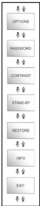
flowchart
graph TD
    A["OPTIONS"] --> B["PASSWORD"]
    B --> C["CONTRAST"]
    C --> D["STAND-BY"]
    D --> E["RESTORE"]
    E --> F["INFO"]
    F --> G["EXIT"]
CONTRAST
- Select and confirm to adjust the OLED display contrast, with an increase in brightness ranging between 0 and 100% and a resolution of 5%.
STAND-BY (Enabling/disabling of automatic power-off and choice of the time period)
- ON/OFF (select and confirm whether you wish to enable/disable the timed stand-by of the control panel).
- →PASSWORD (by selecting and confirming this item you can specify a time period after which the control panels switches to stand-by mode, ranging between 0':10'' - 10':00 and with a resolution of 10'').
RESTORE
- Select and confirm to restore the factory settings.
INFO
- Select and confirm to display the information about the latest firmware version loaded into the system.
EXIT
- Select and confirm to exit the OPTIONS menu.
INGENIA IG3T Cod. 420120239 REV. 1.1
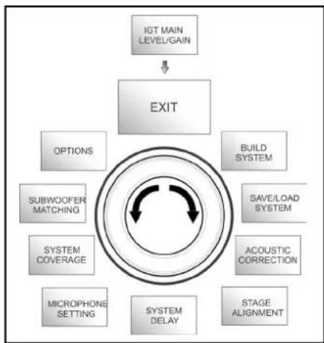
EXIT MENU
When selected and confirmed, this menu allows to return to the initial screen of IG3T.
flowchart
graph TD
    A["IGT MAIN LEVEL/GAIN"] --> B["EXIT"]
    B --> C["OPTIONS"]
    B --> D["BUILD SYSTEM"]
    B --> E["SAVE/LOAD SYSTEM"]
    B --> F["ACOUSTIC CORRECTION"]
    B --> G["STAGE ALIGNMENT"]
    B --> H["SYSTEM DELAY"]
    B --> I["MICROPHONE SETTING"]
    B --> J["SYSTEM COVERAGE"]
    B --> K["SUBWOOFER MATCHING"]
Exit Menu
4. INSTALLATION EXAMPLES

- To use 2 stacked speakers, you need the optional LP-IG accessory. For further information, please refer to the instructions of this accessory.
- Always check that the handles, allowing the infra-red communication, are not obstructed; never cover them and remove any dust or dirt deposits.
- No installation other than that shown here is allowed.
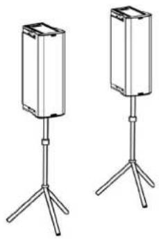
INSTALLATION ON STAND
1 INGENIA IG3T can be installed in both stereo and mono configuration on an optional standard tripod stand, with a pole having a diameter of 35 mm. The maximum permissible height between the base of the speaker and the floor is 120 cm (47.25 in).

ATTENTION!
- Use an appropriately sized stand with the central foot forward to ensure proper stability.
- When "Stacked" on a tripod stand, the INGENIA IG3T cannot be mounted in the configuration with 2 speakers stacked, but only in a single speaker configuration, for safety reasons.
INSTALLATION ON SUBWOOFER
Using the GSA-IG accessory during the installation, you can use the speakers (1 o 2) mounted on subwoofer. This allows to get an extremely compact system, with great output power over the whole range of sound frequencies, installed on the ground. Additional mechanical fixing, or fixing with straps, is required to properly secure the installation. Once the installation is completed, follow the subwoofer configuration instructions in the SUBWOOFER MATCHING section.
INSTALLATION ON SUBWOOFER WITH POLE
It is possible to use a single speaker mounted on 35 mm diameter pole. Additional mechanical fixing, or fixing with straps, is required to properly secure the installation. The maximum permissible height between the base of the speaker and the floor is 120 cm (47.25 in). Once the installation is completed, follow the subwoofer configuration instructions in the SUBWOOFER MATCHING section.
natural_image
Two identical stand-mounted devices with tripod legs, no text or symbols visible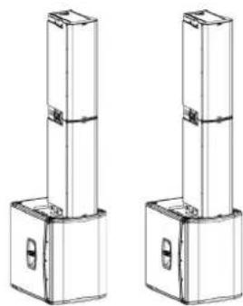
natural_image
Two identical line drawings of a vertical cylindrical structure with base and mounting holes, no text or symbols present.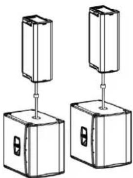
natural_image
Two identical mechanical components with vertical supports and mounting holes, shown from different angles (no text or symbols)INGENIA IG3T Cod. 420120239 REV. 1.1
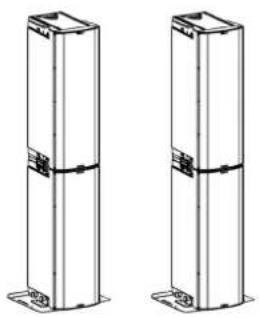
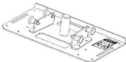
FLOOR INSTALLATION
It is possible a floor installation of 1 or 2 INGENIA IG3Ts using the accessory GSA-IG. A mechanical fixing with screws or screw anchors suited to the type of flooring is required.
natural_image
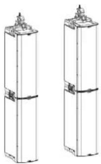
Two identical vertical cylindrical structures with mounting feet, no text or symbols visibleFLOWN INSTALLATION
Flown configuration provides for the hanging of 1 or 2 IG3T speakers, where the optional accessory DRK-IG allows the use of a shackle, and the combination of DRK-IG with the optional truss adapter TA-IG allows fixing on a specific device, such as a rig. When the speakers are in a flown configuration, it is very advisable to use both power supply and signal linking, to reduce the complexity of connections, as shown in the "FIRST SWITCH-ON" section.
natural_image
Two identical cylindrical electronic components with mounting flanges and a base plate, shown from different angles (no text or symbols)
ATTENTION!
- When used outdoors, anchor the speaker to prevent any oscillations due to atmospheric agents and wind.
- Never use the handles to suspend the speaker!
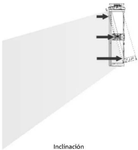
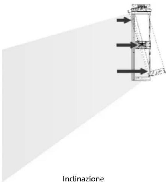
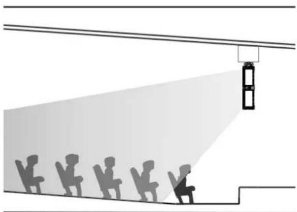
DIGITAL STEERING
Digital steering is a technology that can be suitably adopted to orientate the acoustic coverage of two stacked speakers, modifying it according to the usage context and installation. The DSP of INGENIA IG3T may operate on each individual transducer (whether compression driver or woofer), with differentiated signal output delays. This way the acoustic wavefront of 2 stacked speakers can be regarded as equivalent to that of a single angled speaker, as shown in the figure. In the setup stage, when it automatically detects the presence of 2 speakers through the infra-red ports installed on the handles, IG3T allows to modify the acoustic coverage through a specific menu, SYSTEM COVERAGE (not displayed if the speaker is in a single configuration):
text_image
FAR 0° BACKFor any further information please refer to the section SYSTEM COVERAGE MENU.
natural_image
Diagram showing a person lighting a fire truck at an angle, with silhouettes of other people observing from the vehicle (no text or symbols)Hall
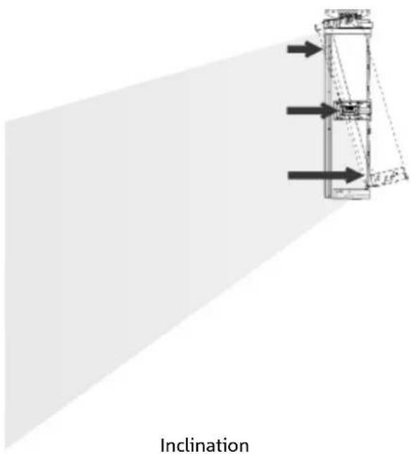
text_image
InclinationINGENIA IG3T Cod. 420120239 REV. 1.1
5. UPDATING THE FIRMWARE
It is very important that you keep the product firmware always up-to-date, to ensure its full functionality. Periodically check the Web site http://www.dbtechnologies.com, in the “DOWNLOADS” section. Once you verify that a new firmware version is available:
- Download the USB BURNER MANAGER in the "SOFTWARE & CONTROLLER" section, then install it following the relevant instructions
- Download the .zip file of the latest firmware in the "DOWNLOADS" section for INGENIA IG3T
- In the top right section of the USB BURNER MANAGER screen, select "File Opening"
- Select the previously downloaded firmware file (verifying that it is appropriate for your operating system)
- Click UPDATE

ATTENTION!
When the firmware is updated the presence of the old saved settings at the next switch-on is not guaranteed.
6. TROUBLESHOOTING
The speaker doesn't turn on:
- Check that the power supply upstream of the system is working properly.
- Verify that the power cord equipped with Neutrik® powerCON TRUE1® connector is properly plugged.
The speaker turns on but it doesn't output any sound:
- Verify that the audio signal input connections have been performed properly, using cables equipped with Neutrik® connectors.
- Check that the cables in use are not damaged.
- Check that the mixer or the audio source are on and that they clearly indicate the presence of an output signal.
- Verify that the gain level in the initial screen is set to an appropriate value.
The speaker is connected, but the control panel is off, including the OLED screen:
- Turn the push rotary encoder to exit any previously activated display standby.
- Verify that the power cord equipped with Neutrik® powerCON TRUE1® connectors is properly plugged.
- Check that the power supply upstream of the system is not cut off.
The speaker outputs a distorted sound:
- Adjust the source volume first, then set the IG3T input gain to an appropriate value.
- Check that the cables in use are not damaged; should that be the case, replace them (a damaged cable may result in a signal loss or alteration).
- Verify the menu settings affecting the frequency content of the output signal and in particular:
a) ACOUSTIC CORRECTION
b) MICROPHONE SETTING if a microphone is connected to the input
The system doesn't detect 2 stacked speakers, and only 1 speaker is displayed in the SYSTEM STRUCTURE screen:
- Verify that you properly mounted the 2 speakers, stacked, with the upper one flipped, and that you used and properly fastened the LP-IG connecting brackets as described in the instructions of this accessory.
- Verify that the upper and lower handles of the speakers, containing the infra-red communication ports, are not covered in any way.
- Repeat the "Selfcheck System" procedure in SYSTEM CHECK, as described in the relevant paragraph.
The settings of the different menus in the control panel cannot be modified, though the speaker is clearly on:
- Verify if any lock password has previously been set.
- Verify that the push rotary encoder operates properly when rotated and pressed.
INGENIA IG3T Cod. 420120239 REV. 1.1
There is a delay in the sound output of the speaker, with respect to that of the source:
- Verify the menu settings affecting the delay of the audio signal and in particular:
The display doesn't clearly show the menu settings:
- Access the menu allowing to adjust the display brightness, OPTIONS → CONTRAST (see the relevant information in the OPTIONS MENU paragraph).
7. TECHNICAL SPECIFICATIONS
GENERAL
| Type: | Vertical 2-way speaker |
ACOUSTIC DATA
| Frequency Response [-10dB]: | 53 - 20.000 Hz |
| Frequency Response [-6dB]: | 57 - 19200 Hz |
| Max SPL: | 132 dB |
| HF compression driver (exit): | 1.4” |
| HF Voice Coil: | 3” (Titanium) |
| HF Type: | Neodymium compression driver |
| Directivity: | Vertical asymmetric |
| Crossover Frequency: | 1100 Hz |
| Coverage (HxV): | 110^ × 90^ (+20^/-70^) |
| LF: | 2 x 10” |
| LF Voice coil: | 2.5” |
| LF Type: | Neodymium |
AMPLIFIER
| Type: | Digipro® G3 |
| Amplification class: | D class |
INGENIA IG3T Cod. 420120239 REV. 1.1
| RMS amplification power: | 900 W |
| Peak power: | 1800 W |
| Interface: | Push rotary encoder + OLED display |
| Automatic rotation display: | Yes |
| Position detection: | EPD |
| Mirroring control (for 2 speakers with IR control): | Yes |
| Inrush current: 48,05 A |
PROCESSOR
| Internal controller: | DSP 56 bit |
| A/D D/A Converter: | 24 bit/48 kHz |
| Settings: | Factory settings and customisable settings that can be saved and recalled |
| Limiter: | Peak, RMS, Thermal |
INPUTS
| Inputs: | 1x Combo (XLR/Jack) balanced/unbalanced |
| Outputs: | 1x XLR link OUT |
| USB: | Mini US, B type |
DIMENSIONS
| Material: | Reinforced PP Polypropylene |
| Grid: | Painted steel / CNC machining |
| Ready for fly-bar: | Yes |
INGENIA IG3T Cod. 420120239 REV. 1.1
| Handles: | 1 upper / 1 lower with IR interface |
| Installation on pole: | Yes, 36 mm |
| Width: | 280 mm (7.68 in) |
| Height: | 806 mm (21.10 in) |
| Depth: | 393 mm (10,67 in) |
| Weight: | 20,8 kg (45,86 lbs) |
INGENIA IG3T Cod. 420120239 REV. 1.1
Features, specification and appearance of products are subject to change without notice. dBTechologies reserves the right to make changes or improvements in design or manufacturing without assuming any obligation to change or improve products previously manufactured.

text_image
AEBA.E.B. Industriale Srl
Via Brodolini, 8
MENÜ SUBWOOFER MATCHING 96
MENÜ OPTIONS....97
PASSWORD 97
CONTRAST....97
STAND-BY 97
RESTORE 97
INFO 97
EXIT....97
MENÜ EXIT....98
INGENIA IG3T Cod. 420120239 REV. 1.1
INHALTSVERZEICHNIS
INSTALLATION AUF STATIV....99
INSTALLATION AUF SUBWOOFER....99
INSTALLATION AUF SUBWOOFER MIT STÄNDER....99
BODENINSTALLATION ....100
HÄNGE-INSTALLATION ....100
DIGITAL STEERING....101
5. AKTUALISIERUNG DER FIRMWARE....102
6. TROUBLESHOOTING....103
natural_image
Technical line drawing of a mechanical device with two circular components and a vertical dimension label (800 and 280), no readable text or symbols beyond measurement lines.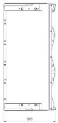
natural_image
Technical line drawing of a rectangular frame with internal cutouts and dimension label (363), no readable text or symbols present.AKUSTISCHES BESCHALLUNGSFELD
natural_image
Technical line drawing of a mechanical clamp or bracket assembly (no text or symbols)Fly Bar DRK-IG LP-IG
text_image
incenium dB 30025 incenium dB 30025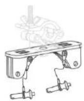
TA-IG truss adapter
natural_image
Technical line drawing of a mechanical assembly with no visible text or symbolsStänder GSA-IG

ACHTUNG!
text_image
System Type BACK Stacked T Flown NEXTStage Alignment Menü

natural_image
Diagram of a street scene with silhouetted figures and a light beam projecting onto a building facade (no text or symbols)großen Innenraum
MENÜ MICROPHONE SETTING
System Coverage Menü
text_image
FAR 0° BACKMENÜ SUBWOOFER MATCHING
natural_image
Two identical stand-mounted devices with tripod legs, no text or symbols visibleINSTALLATION AUF SUBWOOFER
natural_image
Technical line drawing of two vertical cylindrical components with mounting flanges (no text or symbols)INSTALLATION AUF SUBWOOFER MIT STÄNDER
natural_image
Two identical mechanical components with vertical supports and mounting holes, shown from different angles (no text or symbols)INGENIA IG3T Cod. 420120239 REV. 1.1
BODENINSTALLATION
natural_image
Two identical vertical structural panels with mounting feet, shown side by side without any text or symbols.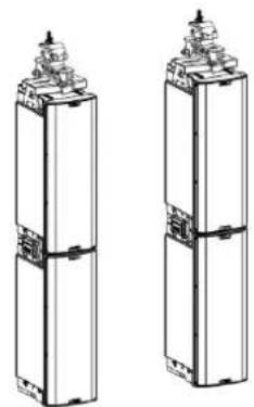
natural_image
Two identical 3D schematic diagrams of cylindrical mechanical components with mounting flanges (no text or symbols)INGENIA IG3T Cod. 420120239 REV. 1.1
DIGITAL STEERING
natural_image
Illustration of a safety camera emitting a beam of light from multiple silhouettes of people, no text or symbols presentHalle
natural_image
Pure mechanical diagram showing a vertical structure with arrows indicating direction, no text or symbols present.Neigung
5. AKTUALISIERUNG DER FIRMWARE
LE MENU SUBWOOFER MATCHING ....131
LE MENU OPTIONS....132
PASSWORD 132
CONTRAST....132
STAND-BY 132
RESTORE 132
INFO 132
EXIT....132
LE MENU EXIT....133
RÉSUMÉ
4. EXEMPLES D'INSTALLATION....134
INSTALLATION SUR STATIF 134
INSTALLATION SUR CAISSON DE GRAVES....134
INSTALLATION SUR CAISSON DE GRAVES AVEC POTENCE ....134
INSTALLATION AU SOL....135
INSTALLATION EN SUSPENSION....135
LE DIGITAL STEERING ....136
5. MISE À JOUR DU FIRMWARE ....137
6. DÉPANNAGE ....138
7. SPÉCIFICATIONS TECHNIQUES ......140
GÉNÉRAL 140
DONNÉES ACOUSTIQUES 140
AMPLIFICATEUR 140
PROCESSEUR 141
ENTRÉES 141
DIMENSIONS....141
INGENIA IG3T Cod. 420120239 REV. 1.1
1. INFORMATIONS GÉNÉRALES
BIENVENUE!
natural_image
Technical line drawing of a mechanical device with circular components and mounting holes (no text or symbols)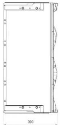
natural_image
Technical drawing of a rectangular frame with internal cutouts and dimension label (390), no readable text or symbols present.COUVERTURE ACOUSTIQUE
natural_image
Technical line drawing of two mechanical components with mounting flanges and mounting holes (no text or symbols)Fly Bar DRK-IG LP-IG
text_image
ngenlA dB352301 ngenlA dB352301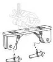
TA-IG truss adapter
natural_image
Technical line drawing of a mechanical assembly with no visible text or symbolsStand GSA-IG

ATTENTION!
text_image
System Type BACK Stacked T Flown NEXTStage Alignment Menu
natural_image
Diagram of a street scene with silhouetted figures and a light beam projecting onto a building facade (no text or symbols)Grande Salle Setting
LE MENU MICROPHONE SETTING
Microphone Setting Menu
text_image
HP Filter 342Hz Antifefeedback 342HzLE MENU SYSTEM COVERAGE
LE MENU SUBWOOFER MATCHING
natural_image
Two identical stand-mounted devices with tripod legs, no text or symbols visibleINSTALLATION SUR CAISSON DE GRAVES
natural_image
Technical line drawing of two vertical cylindrical mechanical components with mounting holes (no text or symbols)INSTALLATION SUR CAISSON DE GRAVES AVEC POTENCE
natural_image
Two identical mechanical components with vertical posts and mounting holes, shown from different angles (no text or symbols)INGENIA IG3T Cod. 420120239 REV. 1.1
INSTALLATION AU SOL
natural_image
Two identical vertical structural columns with mounting feet, shown from different angles (no text or symbols)INSTALLATION EN SUSPENSION
natural_image
Two identical line drawings of vertical cylindrical objects with mounting flanges, no text or symbols present.
ATTENTION!
natural_image
Illustration of a safety camera emitting a beam of light from multiple silhouettes of people, no text or symbols presentSalle
natural_image
Pure mechanical diagram showing a structural component with arrows indicating direction (no text or symbols)Inclinaison
INGENIA IG3T Cod. 420120239 REV. 1.1
5. MISE À JOUR DU FIRMWARE
EL MENu SUBWOOFER MATCHING....166
EL MENU OPTIONS....167
EL MENU EXIT....168
EL DIGITAL STEERING ....171
natural_image
Technical line drawing of a mechanical device with two circular components and a central shaft (no text or symbols)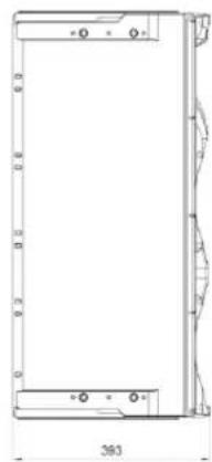
natural_image
Technical line drawing of a rectangular frame with mounting holes and dimension label (360), no readable text or symbols present.COBERTURA ACÚSTICA
natural_image
Technical line drawing of a mechanical clamp or bracket assembly (no text or symbols)Fly Bar DRK-IG Abrazaderas de sujeción LP-IG
text_image
Incena dB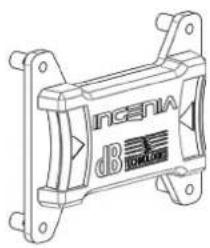
natural_image
Technical line drawing of a mechanical component with mounting brackets and a central label (no readable text or symbols)
natural_image
Line drawing of a tall refrigerator with front panels and side door (no text or symbols)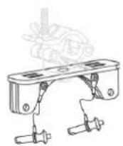
TA-IG truss adapter
natural_image
Technical line drawing of a mechanical device casing with internal components (no text or symbols)Stand GSA-IG

¡ATENCIÓN!
natural_image
Line drawing of a vertical rectangular device with internal components and mounting brackets (no text or symbols)PARTE INFERIOR
PARTE SUPERIOR
PARTE SUPERIOR
PARTE INFERIOR
INGENIA IG3T Cod. 420120239 REV. 1.1
Menu Stage Alignment
EL MENU SYSTEM DELAY
natural_image
Diagram of a street scene with silhouettes and a light beam, no text or symbols presentMenu Microphone Setting

text_image
HP Filter 342Hz Antifefeedback 342HzINGENIA IG3T Cod. 420120239 REV. 1.1
EL MENU SYSTEM COVERAGE
EL MENU SUBWOOFER MATCHING
natural_image
Two identical stand-mounted devices with tripod legs, no text or symbols visiblenatural_image
Technical line drawing of two vertical cylindrical components with mounting flanges (no text or symbols)natural_image
Two identical mechanical components with vertical posts and mounting holes, shown from different angles (no text or symbols)INGENIA IG3T Cod. 420120239 REV. 1.1
natural_image
Two identical vertical cylindrical structures with mounting feet, shown side by side without any text or symbols.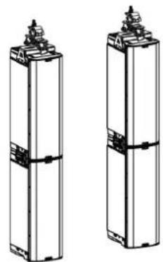
natural_image
Two identical cylindrical electronic components with mounting flanges and connectors, shown from top and side views (no text or symbols)INGENIA IG3T Cod. 420120239 REV. 1.1
EL DIGITAL STEERING
natural_image
Diagram showing a fire safety scene with silhouettes of people and a fire extinguisher emitting a beam (no text or symbols)Platea