20233 - Bike rack Berger & Schröter - Free user manual and instructions
Find the device manual for free 20233 Berger & Schröter in PDF.
| Brand | Berger & Schröter |
| Model | 20233 |
| Product type | Bike carrier with plug-in coupling |
| Net weight | Approximately 2 kg |
| Mounting plate dimensions | 135 x 80 mm |
| Material | High-quality steel alloy |
| Towbar compatibility | Steel trailer tow balls min. quality ST52-3 |
| Maximum payload | 59 kg (according to compatible towbar) |
| Maximum total weight (carrier + load) | 70 kg |
| Mounting kit included | 4 screws M8,9x30, 4 washers U, 4 self-locking nuts M8 |
| Tightening torque | 49 Nm for the fixing screws |
| Fixing system | Plug-in coupling with clamping screw |
| Foldable function | No (standard model 20233; foldable version ref. 20234) |
| Maintenance | Check fixings after 50 km; clean and degrease the ball before mounting |
| Safety | Use only the supplied self-locking nuts; observe tightening torques |
| Intended use | Transport of bicycles on vehicle rear towbar |
| Standards | Compliant with StVZO requirements (Germany) |
Frequently Asked Questions - 20233 Berger & Schröter
User questions about 20233 Berger & Schröter
0 question about this device. Answer the ones you know or ask your own.
Ask a new question about this device
Download the instructions for your Bike rack in PDF format for free! Find your manual 20233 - Berger & Schröter and take your electronic device back in hand. On this page are published all the documents necessary for the use of your device. 20233 by Berger & Schröter.
USER MANUAL 20233 Berger & Schröter
natural_image
3D wireframe diagram of a rectangular grid structure with an arrow pointing to one side (no text or symbols)NSAI – National Standards Authority of Ireland – Technical Service No. 91
natural_image
Mechanical component with a black lever and mounting base (no visible text or symbols)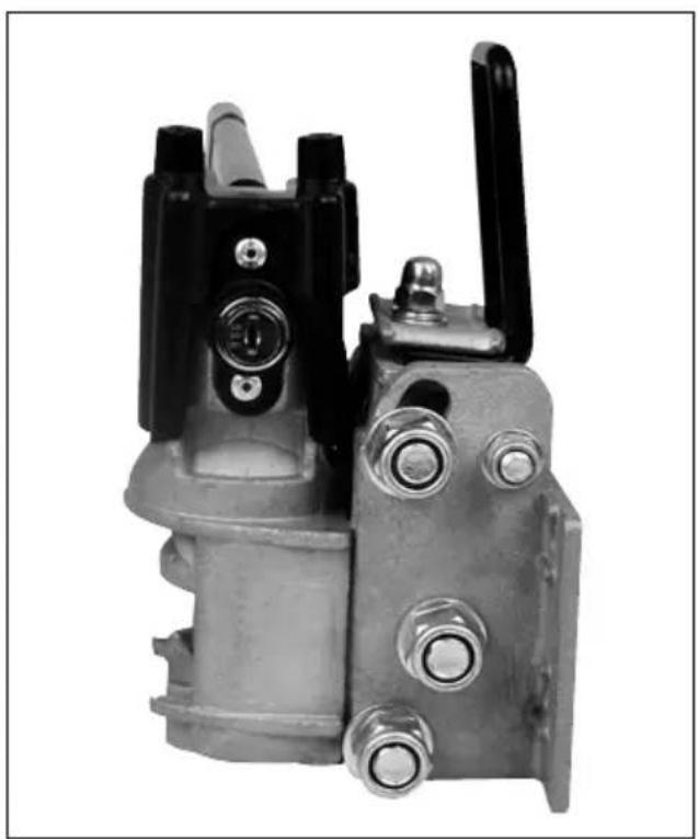
natural_image
Mechanical component with black and metallic parts, no visible text or symbolsnatural_image
Two black-and-white photos showing a hand holding a mechanical switch, with no visible text or symbols.natural_image
Mechanical assembly diagram showing a lever mechanism with a pulley and pivot point (no text or labels)natural_image
Illustration of a hand using a tool to lift a beam, with an inset showing a human arm flexing (no text or symbols present)natural_image
Illustration of a person using a bench presser to lift a bed, with motion arrows indicating movement (no text or symbols)natural_image
Illustration of a hand gripping a mechanical device with an inset showing a flexing arm (no text or symbols present)natural_image
Illustration of a person in protective gear handling equipment with directional arrows indicating movement (no text or symbols)text_image
Technical diagram showing mechanical assembly steps with directional arrows and a magnified inset of a component with internal flow arrows.natural_image
Mechanical component with threaded shaft and mounting flange (no visible text or symbols)natural_image
Cross-sectional view of a mechanical valve assembly (no visible text or labels)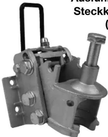
natural_image
Mechanical component with attached spring and mounting bracket (no visible text or symbols)text_image
Technical diagram of a pipe elbow with labeled components and dashed lines indicating hidden edges(GB) Assembly and Operating Instructions for rear mounted carrier systems, type: ProfiTech
Please read these operating instructions carefully before use and keep them in a safe place for future reference.
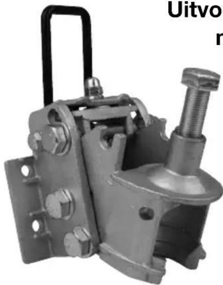
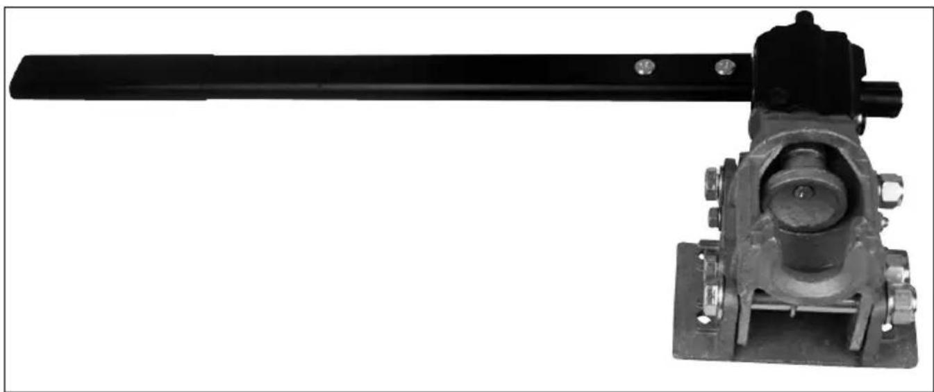
Model: Rear carrier with quick release lever coupler (item no. 20121) Item no. 30726 powder-coated, grey; item no. 31144 galvanised
text_image
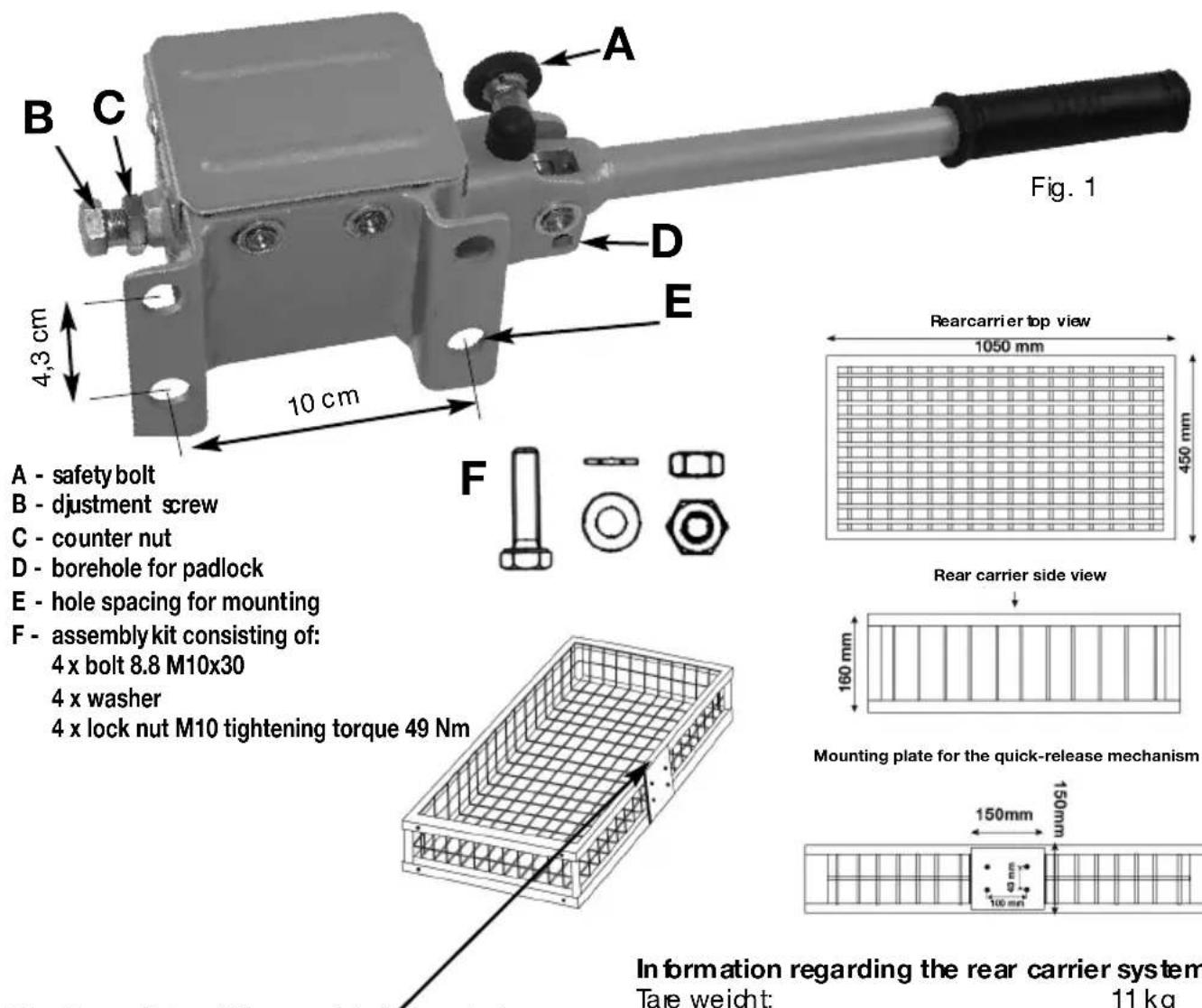
Fig. 1 A - safety bolt B - djustment screw C - counter nut D - borehole for padlock E - hole spacing for mounting F - assembly kit consisting of: 4 x bolt 8.8 M10x30 4 x washer 4 x lock nut M10 tightening torque 49 Nm A C D E 4,3 cm 10 cm F Rearcarrier top view 1050 mm 450 mm Rear carrier side view Mounting plate for the quick-release mechanism 160 mm 150mm 100mm Information regarding the rear carrier system Tare weight: 11 kgThe type plate of the models is located on the inside of the mounting plate for the quick-release mechanism
Information regarding the rear carrier system
Tare weight: 11 kg
Permissible payload/carrying capacity: 9 kg
Permissible total weight carrier
(Tare weight and payload): 70 kg
DEKRA test report only applies to the models item no. 30726 and item no. 31144
Scope of application
The rear carrier system type ProfiTech is intended to transport game and can only be used in connection with a type approved tow ball with brackets (DIN 74058 / ISO 1302) suitable for mounting the rear carrier system and which is mounted on the motor vehicle.
Some vehicle manufacturers also give approval to use rear carrier systems for the standard tow coupling mounted on the vehicle. For this purpose, the permissible loads and geometries are described in the operating instructions for the vehicles. These are decisive for the use of the rear carrier systems.
If there is no approval to use rear carrier systems for the respective tow coupling, the suitability test must be conducted as described below. The suitability test was prepared based on § 30 of the Road Traffic Licencing Regulations (StVZO) – instructions on the application of rear mounted carrier systems on passenger cars and caravans.
Suitability test for the tow coupling
The rear carrier system can be mounted onto a type approved tow coupling under the following conditions:
- The ball and the tow bar must consist of one single piece.
- The material of the tow bar must have a minimum quality of St 52-3 (tow bars are usually made of an St 52-3 material).
- The area between the ball and the fixing point cannot indicate any weakening. (welding point or the like).
- The permissible drawbar load on the tow coupling (refer to nameplate on the tow coupling) must amount to at least 70 kg.
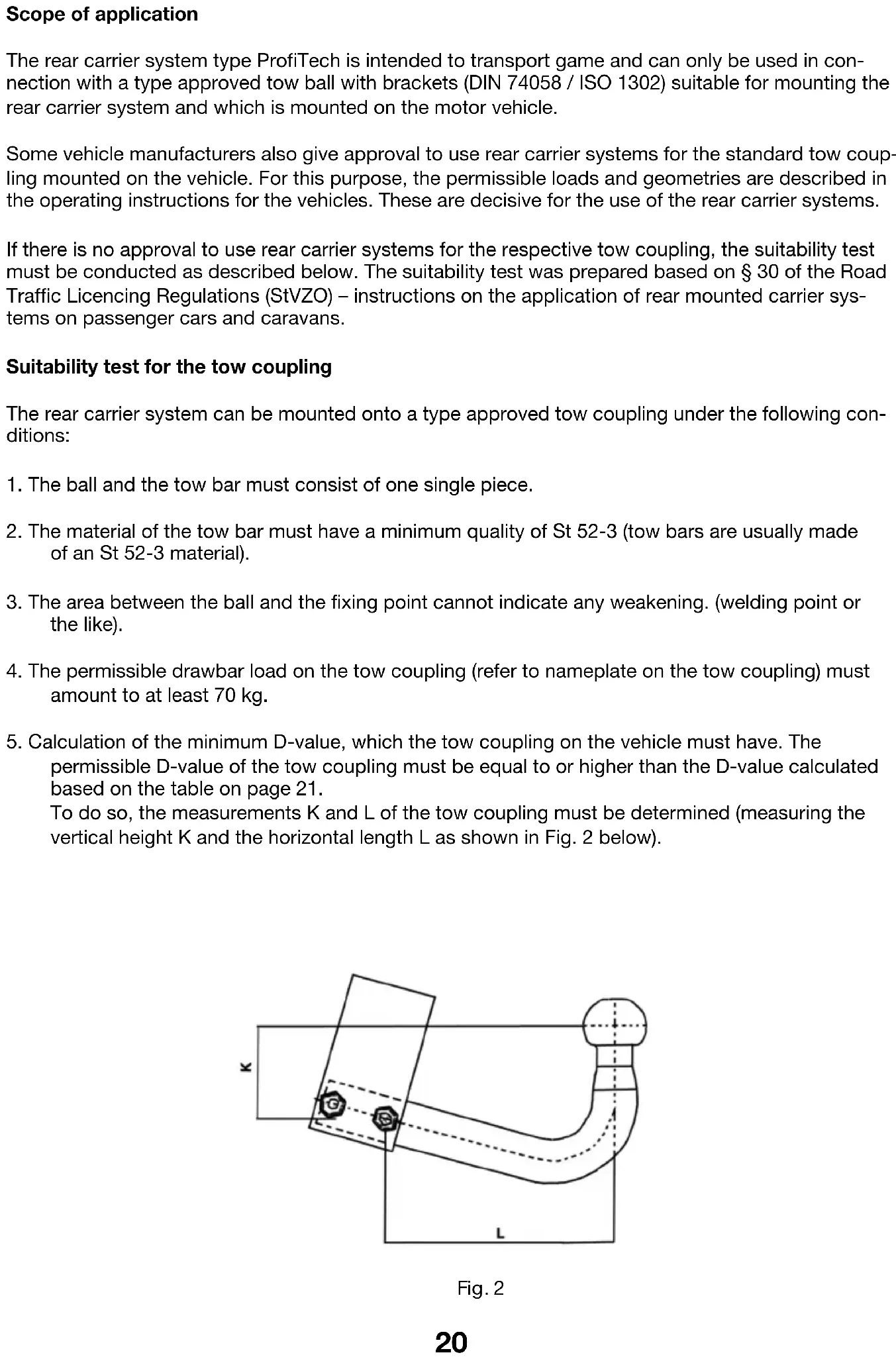
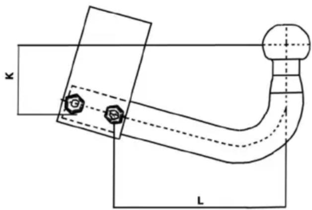
- Calculation of the minimum D-value, which the tow coupling on the vehicle must have. The permissible D-value of the tow coupling must be equal to or higher than the D-value calculated based on the table on page 21.
To do so, the measurements K and L of the tow coupling must be determined (measuring the vertical height K and the horizontal length L as shown in Fig. 2 below).
text_image
K LFig. 2
Calculation of the minimum D-value, which your tow coupling must have:
D-value in kN
Compare the calculated D-value from the table with the information regarding the D-value on the nameplate of the tow coupling (if you are unable to find the nameplate for the tow coupling, request the D-value and the permissible drawbar load from your authorised service centre, the car manufacturer or from the manufacturer of the tow coupling).
Example:
D-value according to nameplate: 10.5 kN
permissible drawbar load: 70 kg
vertical height K: 80 mm
horizontal length L: 250 mm
- Comparison permissible drawbar load has been met because there is a minimum drawbar load of 70 kg.
- Now, look at the D-value in the table at the interface 80 mm height/250 mm length, in this case 7.1. With it, the requirement is met; this D-value of the tow coupling is higher than the minimum D-value calculated from the table.
- That results in the rear carrier being able to carry a payload of 59 kg (max. payload of the rear carrier).
Preparation and assembly of the rear carrier on the tow coupling
Mount the quick coupling on the rear carrier basket using the enclosed mounting materials (4 bolts M10x25, 4x washers,
4 lock nuts). (please refer to page 8, Fig. 1).
Then, mount the quick-release mechanism to the rear carrier basket using the enclosed mounting screws. Please make sure that all screwed connections are tightened appropriately (observe tightening torque). Only use the enclosed lock nuts. All grease must be removed from the tow ball before placing and mounting the rear carrier on the tow coupling.
Pull out the safety bolt (A) and rotate it 1/4 turn.
Now, the lever can be flipped upwards. Both ball clamping jaws in the quick-release mechanism open.
Place the rear carrier onto the tow ball and press the lever halfway down, so that the carrier can still be adjusted horizontally.
If the rear carrier is aligned horizontally behind the car, press the hand lever all the way down and secure it using the safety bolt.
Important: the contact pressure of the ball clamping jaws must be readjusted or readapted to every tow coupling, to achieve the required clamping stability.
To do so, first loosen the counter nut (C), to then tighten the adjustment screw (B) with 32 Nm using a torque wrench. At the same time, the hand lever must be in the clamping position (pressed down).
Then, retighten the counter nut.
The contact pressure of the ball clamping jaws must be checked at regular intervals.
This adjustment must be repeated for every vehicle/coupling change. If you do not have a torque wrench, have this adjustment work conducted in a workshop.
You can protect the rear carrier against theft by inserting a padlock into the holes (D) intended for this purpose.
Safety notice:
After driving approx. 50 km, the fit of the rear carrier including the load must be checked; the adjustment screw (B) may need to be retightened.
Disassembling the rear carrier
- Disconnecting the electrical connection.
- Pull out the safety bolt (A) and rotate it 1/4 turn (refer to Fig. 1).
- Flip the hand lever upwards. In the process, hold onto the basket firmly, so that it cannot flip downwards and damage the vehicle.
- Lift the basket with the quick coupling off the tow coupling in an upward direction. Pay attention not to damage your vehicle by means of fast, uncontrolled movements.
General information
Rear lighting installations and licence number.
If the vehicle's tail lights and/or licence plate number are partially or fully covered by the rear carrier or the load, the vehicle lighting and/or the licence plate number must be revised.
| First registration of the vehicle | |||
| Lighting as of 01/01/1987installation prior to 01/01/1987 until 31/12/1990 ab 01.01.1991 | |||
| Backup lights optional mandatory mandatory | |||
| Fog tail lamp optional optional mandatory | |||
The lighting optional at the time of the first registration of the vehicle does not need to be revised.
Securing of loads
The vehicle driver is responsible for the load being properly secured in accordance with the Road Traffic Regulations (StVO). Pay particular attention that the load does not extend farther than 40 cm beyond the outer edge of the light-emitting surface of the tail lights.
Additional information
On the side, the rear carrier cannot project beyond the end of the vehicle.
The axle load distribution specified by the vehicle manufacturer is altered by the load placed on the rear of the vehicle. This alteration cannot lead to the permissible axle load being exceeded.
The manner of driving must be adapted to the load condition and if necessary, changed vehicle handling
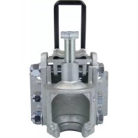
Model: Rear carrier for tow couplings, with quick release lever coupler, hinged, (item no. 20215)
Please read these operating instructions carefully before use and keep them in a safe place for future reference.
natural_image
Mechanical component with a black lever and mounting base (no visible text or symbols)
natural_image
Mechanical component with black and metallic parts, no visible text or symbolsView of the hinged mechanism closed.
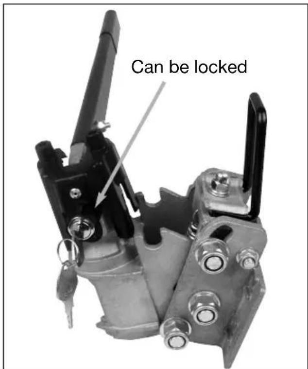
text_image
Can be lockedView of the hinged mechanism opened.
Assembly instructions/Assembly
text_image
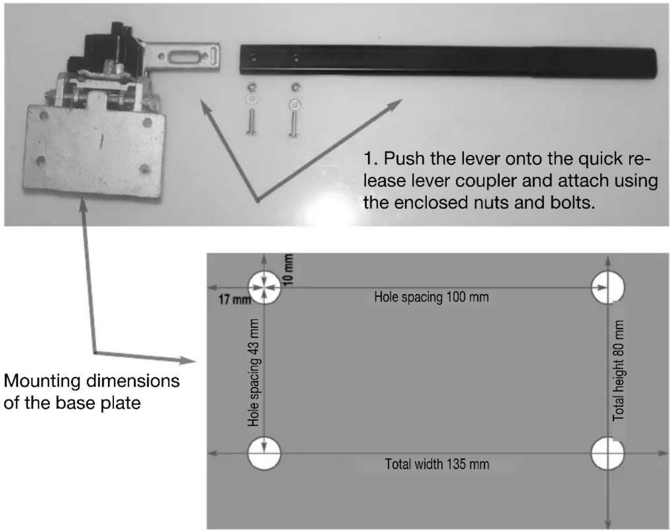
1. Push the lever onto the quick release lever coupler and attach using the enclosed nuts and bolts. Mounting dimensions of the base plate Hole spacing 100 mm Hole spacing 43 mm Total height 80 mm Total width 135 mm
natural_image
Mechanical component with metal parts and a separate black bracket, no visible text or symbols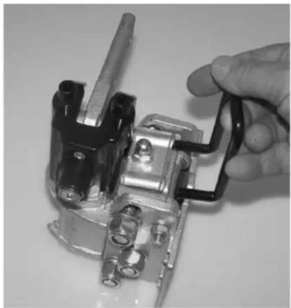
natural_image
Close-up of a hand holding a mechanical component with metal parts and a black handle (no visible text or symbols)- Insert the enclosed handle for the hinged mechanism into the quick release lever coupler and tighten with a wrench. Tighten to 6 Nm using a torque wrench.
Adjusting to the tow coupling
natural_image
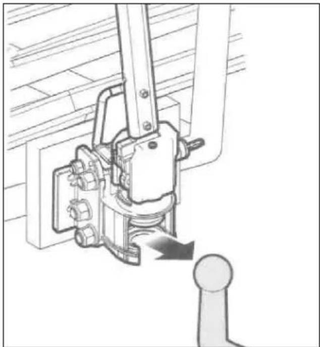
Mechanical assembly diagram showing a lever mechanism with a pulley and pivot point (no text or labels)- Place the quick release lever coupling on the tow coupling.
The quick release lever coupler is suitable for steel tow couplings, not for aluminium tow couplings.
natural_image
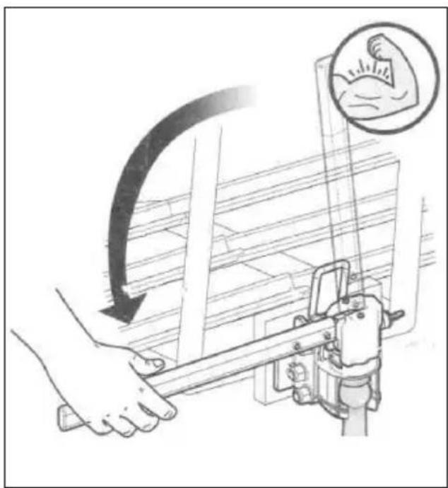
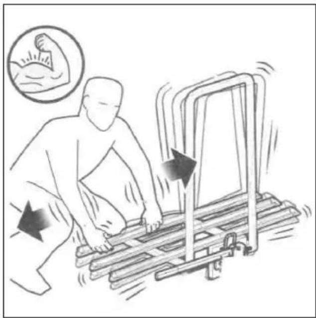
Illustration of a hand using a tool to lift a beam, with an inset showing a human arm flexing (no text or symbols present)- Press the lever down until it locks into place.
natural_image
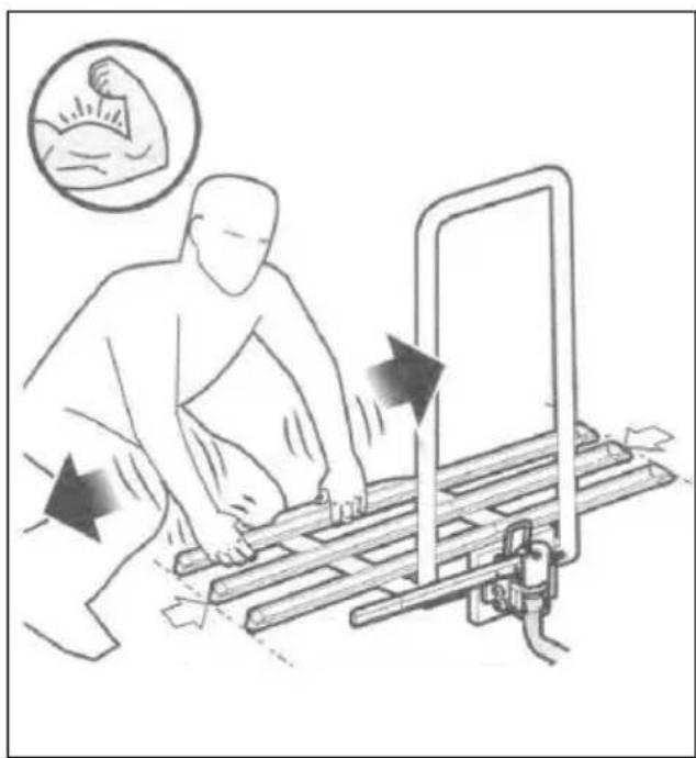
Illustration of a person using a bench presser to lift a bed, with motion arrows indicating movement (no text or symbols)- The quick release lever coupler should fit tightly now and cannot be able to move freely to the right/left or up/down.
natural_image
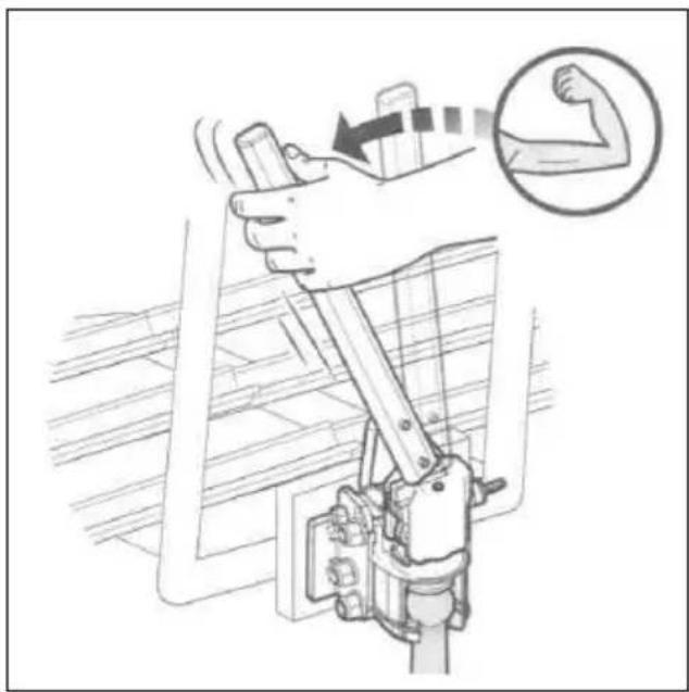
Illustration of a hand gripping a mechanical device with an inset showing a flexing arm (no text or symbols present)- If the lever does not lock into place at the bottom without excessive force, it must be readjusted as shown below.
natural_image
Illustration of a person in protective gear performing a physical exercise with motion arrows, no text or symbols present.- The lever can be easily locked into place at the bottom but the quick release lever coupler freely move to the right/left or up/down. Now, readjustment must take place as shown below.
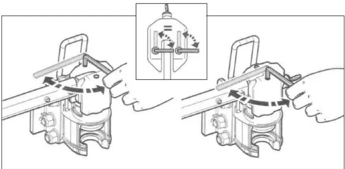
text_image
Technical diagram showing mechanical assembly steps with directional arrows and a magnified inset of a component with internal flow arrows.- Turn both the top hexagon socket nuts respectively to the right or left using the enclosed Allen wrench, depending on whether the quick release lever coupler is to tightly or loosely fitted on the tow coupling. If the lever now locks into place at the bottom without excessive force and the quick release lever coupler cannot move freely to the right/left or up/down, the quick release lever coupler is adjusted optimally.
natural_image
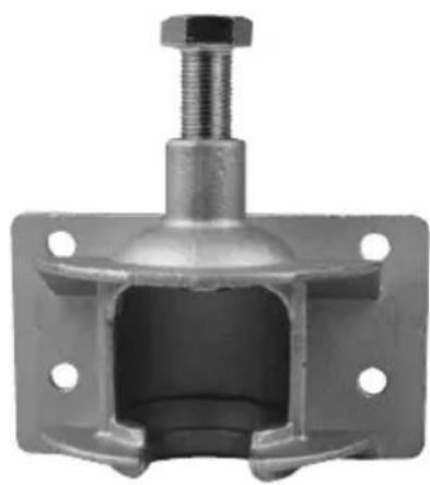
Mechanical component with bolted head and flange (no visible text or symbols)Model: Rear carrier with plug-in coupling (item no. 20233)
Screw the plug-in coupling for rear carriers onto the rear carrier using the enclosed assembly kit.
Assembly kit consisting of:
4 x bolt 8.8 M8,9x30
4 x washer
4 x lock nut M8 tightening torque 49 Nm Now, simply insert the rear carrier, tighten bolt and done!
Weight approx. 2 kg. Mounting plate dimensions 135x80 mm, high quality steel alloy, suitable for steel ball couplings with at least ST52-3.
natural_image
Cross-sectional view of a mechanical valve assembly (no visible text or labels)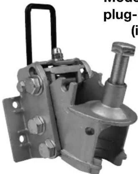
natural_image
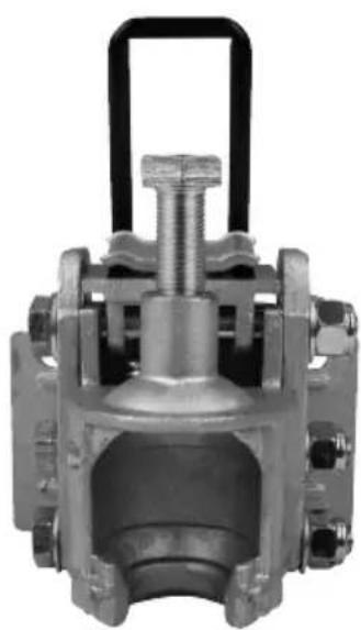
Mechanical component with bolts and a threaded shaft (no visible text or symbols)Model: Rear carrier with plug-in coupling, hinged (item no. 20234)
Screw the plug-in coupling, hinged, for rear carriers onto the rear carrier using the enclosed assembly kit.
Assembly kit consisting of:
4 x bolt 8.8 M8,9x30
4 x washer
4 x lock nut M8
tightening torque 49 Nm
Now, simply insert the rear carrier - tighten bolt and done!
Weight approx. 2 kg. Mounting plate dimensions 135x80 mm, high quality steel alloy, suitable for steel ball couplings with at least ST52-3.
natural_image
Mechanical component with a black lever and mounting base (no visible text or symbols)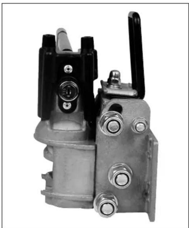
natural_image
Mechanical component with black and metallic parts, no visible text or symbolsnatural_image
Mechanical component with metal parts and a separate black bracket (no visible text or symbols)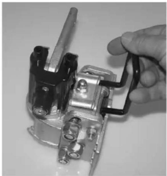
natural_image
Close-up of a hand holding a black mechanical component with metal parts and bolts (no visible text or symbols)natural_image
Mechanical assembly diagram showing a lever mechanism with a pulley and pivot point (no text or symbols)natural_image
Illustration of a hand using a tool to lift a beam, with an inset showing a human arm flexing (no text or symbols present)natural_image
Illustration of a person using a bench presser to lift a bed, with motion arrows indicating movement (no text or symbols)natural_image
Illustration of a hand gripping a mechanical device with an inset showing a flexing arm (no text or symbols present)natural_image
Illustration of a person in protective gear handling equipment with directional arrows indicating movement (no text or symbols)text_image
Technical diagram showing mechanical assembly steps with directional arrows and a magnified inset of a component with internal flow arrows.natural_image
Mechanical component with threaded shaft and flange (no visible text or symbols)natural_image
Cross-sectional view of a mechanical valve assembly (no visible text or labels)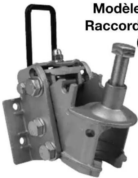
natural_image
Mechanical component with threaded shaft and mounting bracket (no visible text or symbols)natural_image
Mechanical component with a black lever and mounting base (no visible text or symbols)
natural_image
Close-up of a mechanical component with black and metallic parts, no visible text or symbols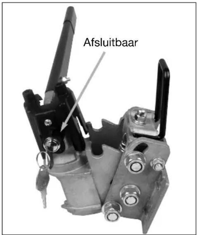
text_image
Afsluitbaarnatural_image
Two black-and-white photos showing a hand adjusting a mechanical switch component; no text or symbols visible.natural_image
Mechanical assembly diagram showing a lever mechanism with a pulley and pivot point (no text or labels)natural_image
Illustration of a hand using a tool to lift a beam, with an inset showing a human arm flexing (no text or symbols present)natural_image
Illustration of a person using a bench presser to lift a bed, with motion arrows indicating movement (no text or symbols)natural_image
Illustration of a hand gripping a mechanical device with an inset showing a flexing arm (no text or symbols present)natural_image
Illustration of a person in protective gear handling equipment with directional arrows indicating movement (no text or symbols)text_image
Technical diagram showing mechanical assembly steps with directional arrows and a magnified inset of a component with internal flow arrows.natural_image
Mechanical component with bolted head and flange (no visible text or symbols)natural_image
Cross-sectional view of a mechanical valve assembly (no visible text or labels)