BBM5 WP - Speaker ANT - Free user manual and instructions
Find the device manual for free BBM5 WP ANT in PDF.

User questions about BBM5 WP ANT
0 question about this device. Answer the ones you know or ask your own.
Ask a new question about this device
Download the instructions for your Speaker in PDF format for free! Find your manual BBM5 WP - ANT and take your electronic device back in hand. On this page are published all the documents necessary for the use of your device. BBM5 WP by ANT.
USER MANUAL BBM5 WP ANT
natural_image
Line drawing of a rectangular electronic device with a hexagonal top and circular base (no text or symbols)
ES MANUAL DE USO | SECCION 1
IT MANUALDE D'USO | SEZIONE 1 DE BIDLENUGESANUTLUNG | KAPITEL 1
FR NOTICE D:\EPM\OLI | SECTION 1
IT MANUALÉ D'USO | SEZIONE 1
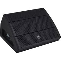
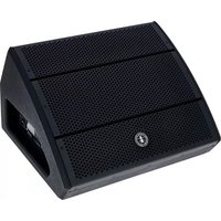
BBM BP/WP SERIES
PASSIVE MINIBOX SPEAKERS
DIFFUSORI MINIBOX PASSIVI
ENCEINTES MINIBOX PASSIVES
PASSIVE MINIBOX-LAUTSPRECHER
DIFUSORES MINIBOX PASIVOS
BBM 3BP/WP | BBM 5BP/WP | BBM 8BP/WP
BBM BP/WP SERIES
TABLE OF CONTENTS
| 1 | Introduction | 3 |
| 2 | Installation | 4 |
| 3 | Description | 5 |
| 3.1 | Inputs & controls 5 | |
| 4 | Connections | 6 |
| 4.1 | Constant voltage 6 | |
| 4.2 | Constant impedance | 7 |
| 5 | Troubleshooting | 8 |
| 6 | Technical specifications 9 | |
| 7 | Optional accessories 10 | |
| 8 | Notes 11 |
PACKAGE CONTENT
• 1x Passive minibox speaker
• 1x User manual - Section 1
• 1x User manual - Section 2
The warnings in this manual must be observed together with the "USER MANUAL - SECTION 2".
1 | INTRODUCTION
Thank you for choosing a A.N.T - Advanced Native Technologies - product!
In BBM BP/WP speaker series we have put our passion and our technological background gained over the years, to offer products that meet your needs, maintaining the quality over time.
Specifically designed for an immediate and user-friendly application, meeting the needs of those looking for a compact constant impedance or voltage (70-100V) audio system, providing excellent performance and the best value for money possible in its category.
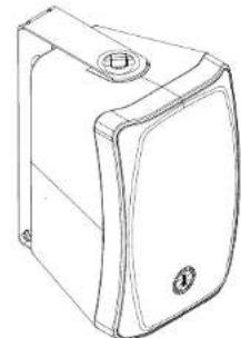
Characterized by an elegant look and compact dimensions, these speakers are able to amplify indoors and outdoors - thanks to IP55 protection - small and medium-sized environments. All models are available in two colors, black (BBM BP) and white (BBM WP).
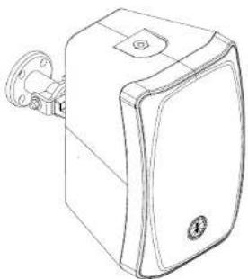
Are also available, specifically engineered for BBM speakers wall or ceiling installation, the bracket kits BBM WBU and BBM 358Y in black or white, as well as the SA-30/50/80 black kits specific tripod mounting.
Please, dedicate some minutes to read this instruction manual in order to quickly achieve the best performances from this product.
For safety precautions, warranty and disposal, please refer to attached Section 2.
For further information about all A.N.T products catalog, please visit our website: www.ant-intomusic.com.

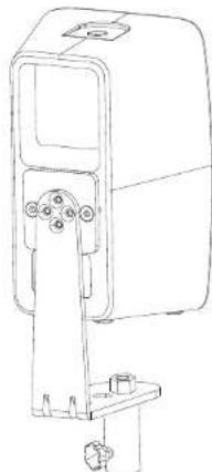
2 | INSTALLATION
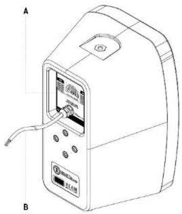
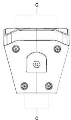
Each speaker is equipped with:
A | Sealed power selector.
B | Headed input cable.
C | Non-slip rubber feet.
natural_image
Technical line drawing of a mechanical component with mounting holes and a central hexagonal feature (no text or symbols)WARNING:
For installation please contact qualified personnel. In order to avoid any danger, place and fasten the speaker in a stable and secure way. Install the speaker as explained in this instruction manual.
WARNING:
For safe use of the accessory, check functionality and integrity before installation and periodically.
4 User manual | BBM BP/WP Series

3 | DESCRIPTION
3.1 | INPUTS & CONTROLS
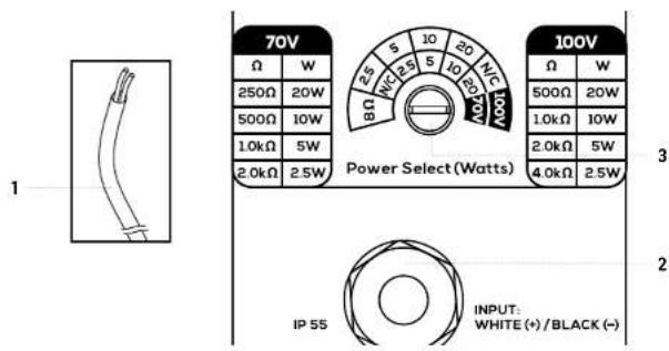
1 HEADED INPUT CABLE
Connect the signal from amplifier outputs to these two wires. To ensure correct sound reproduction, the speakers must be connected in phase. Match the positive and negative polarities of the amplifier with the positive (White +) and negative (Black -) polarity of the speaker input.
2 CABLE GLAND
The cable gland guarantees IP55 protection of electrical connections inside the speaker.
3 SEALED POWER SELECTOR
IP55 Selector with seven positions for constant impedance (8Ω) or constant voltage (10W, 20W, 40W or 80W on 70V or 100V) connections. Use a flat-blade screwdriver to select the desired mode.
NOTE:
All the BBM BP/WP series speakers guarantee IP55 protection, in particular.
• Total protection against item introduction.
- Protection against liquids entry in any form like drops, vapors, sprays and weak jets of water in any direction.
• Dust and liquids intrusion must not damage the equipment.
BBM BP/WP Series | User manual
4 | CONNECTIONS
For the installation of the speaker and to guarantee its proper operation, strictly apply the instructions below:
- It is recommended to contact qualified personnel, i.e. personnel with sufficient technical knowledge, experience or specific instructions, able of properly making the connections and preventing the dangers of electricity. The entire sound system must be made in compliance with existing standards and laws concerning electrical systems.
• To avoid the risk of electric shock, connect the speaker with the amplification system turned off. - Before operating the speaker, carefully check the correct connection to avoid accidental short circuits that can cause electric sparks. The speaker can be connected to 70V or 100V constant voltage (high impedance) or B Ohm constant impedance (low impedance) audio lines.
Make the connections using the White (+) and Black (-) wires in the back of the speaker. (Fig.1)
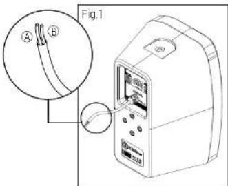
Ⓐ COM - Black (-) Ⓑ 70V/100V/8Ω - White (+)
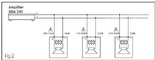
4.1 | CONSTANT VOLTAGE SYSTEMS (Fig.2)
The input voltage of the speaker must match the voltage selected on the amplifier, and the sum of the power of all the speakers connected to the audio line must not exceed the nominal power of the amplifier.
Make the connections taking into consideration the following indications:
- Use cables of adequate section. A greater distance between the amplifier and the speakers requires larger section cables. This avoids signal losses due to line length.
• To prevent inductive phenomena from causing buzzing and disturbs, and compromising the proper functioning of the system, the connection cables must
not be placed in the same cable duct or close to devices producing strong magnetic fields (e.g. power transformers), conductors of electricity and lines that power speakers. Furthermore, to minimize the inductive effects due to coupling with electric fields, use cables with twisted conductors.
- To ensure correct sound reproduction it is necessary to connect the speakers "in phase", I. e. the positive and negative polarities of the amplifier must correspond to the positive (70-100V) and negative (COM) polarity of the speaker input.
- To simplify the connection, it is possible to use bipolar cables with a marking (e.g. different colors) which distinguishes the polarity.
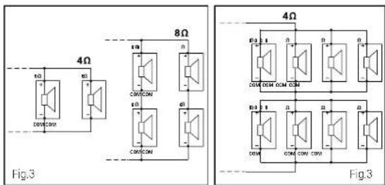
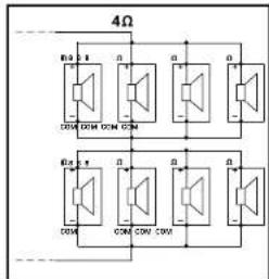
4.2 | CONSTANT IMPEDANCE SYSTEMS (Fig.3)
The total load impedance of all the speakers must be higher than nominal impedance of the amplifier and the length of the connection cables must be reduced to the minimum.
5 | TROUBLESHOOTING 6 | TECHNICAL SPECIFICATIONS
| PROBLEM SOLUTION | |
| No sound or too low sound | Make sure that the connection cable between the speaker and the amplifier is working and properly connected. |
| Make sure the loudspeaker power selector is set correctly, ie too low power has not been chosen. | |
| Distortion | Make sure that the speaker power selector is set correctly, which means that too high power has not been chosen. |
| Sound quality problem Check the source signal | |
| Make sure the loudspeaker power selector is properly set, i.e. has not been chosen power too low or too high. |

| BBM-3BP/3WP BBM-5BP/5WP BBM-8BP/8WP | |||
| System 2-way vented box 2-way vented box 2-way vented box | |||
| LF 3.5" custom speaker1" V.C | 5" custom speaker1" V.C | 8" custom speaker1" V.C | |
| I.F 0.8" neodymium dome driver | 1" neodymium dome driver | 1" neodymium dome driver | |
| Frequency response(+/-10dB) | 140Hz-20kHz 100Hz-20kHz 55Hz-20kHz | ||
| Nominal power 20W RMS/8Q -10W/20W/40W/80W@ 70V and 100V | 40W RMS/8Q -10W/20W/40W/80W@ 70V and 100V | 80W RMS/8Q -10W/20W/40W/80W@ 70V and 100V | |
| Input cable Headed cable 2x1White (+) Black (-) | Headed cable 2x1White (+) Black (-) | Headed cable 2x1White (+) Black (-) | |
| Suspension system | 2 M6 - top/under for U bracket mount4 M5 - rear for Y and SA brackets | 2 M6 - top/under for U bracket mount4 M5 - rear for Y and SA brackets | 2 M6 - top/under for U bracket mount4 M5 - rear for Y and SA brackets |
| Cabinet material ABS ABS ABS | |||
| Available colours | WhiteBBM 3WP model | WhiteBBM 5WP model | WhiteBBM 8WP model |
| BlackBBM 3BP model | BlackBBM 5BP model | BlackBBM 8BP model | |
| Dimensions(W x H x D) | 134.3 x 220.4 x 136.4mm | 170.5 x 272 x 171.8mm | 250 x 400 x 251mm |
| Net weight | 2.1Kg | 3Kg | 6Kg |
| OPTIONAL ACCESSORIES | |||
| U bracketskit for wall mounting | BBM-WB3U(black or white) | BBM-WB3U(black or white) | BBM-WB3U(black or white) |
| Y bracketsrotation and tilting kit for wall/celling mounting | BBM 358Y(black or white) | BBM 358Y(black or white) | BBM 358Y(black or white) |
| Tripod mount kit | BBM-SA30 (D25mm) | BBM-SA50 (D35mm) | BBM-SA80 (D35mm) |
7 | OPTIONAL ACCESSORIES 8 | NOTES
natural_image
Line drawing of a rectangular device with a circular top and base (no text or symbols)U brackets kit for wall mounting
natural_image
Line drawing of a mechanical device with a clamped bracket and mounting bracket (no text or symbols)Y brackets rotation and tilting kit for wall/ceiling mounting
natural_image
Technical line drawing of a mechanical device with mounting bracket and housing (no text or symbols)Tripod mount kit
BBM BP/WP SERIES
INDICE
natural_image
Technical line drawing of a mechanical component with mounting holes and a central hexagonal feature (no text or symbols)ATTENZIONE:
Ⓐ COM - Nero (-)
⑧ 70V/100V/8Ω - Bianco (+)
4.1 | IMPIANTI A TENSIONE COSTANTE (Fig.2)
natural_image
Line drawing of a rectangular device with a circular button and mounting bracket (no text or symbols)natural_image
Line drawing of a mechanical device with a clamped bracket and mounting bracket (no text or symbols)natural_image
Technical line drawing of a mechanical device with mounting bracket and housing (no text or symbols)natural_image
Technical line drawing of a mechanical component with mounting holes and a central hexagonal feature (no text or symbols)ATTENTION :
Ⓐ COM - Noir (-)
⑧ 70V/100V/8Ω - Blanc (+)
natural_image
Line drawing of a rectangular device with a circular button and mounting bracket (no text or symbols)natural_image
Line drawing of a rectangular electronic device with mounting bracket and control panel (no text or symbols)natural_image
Technical line drawing of a mechanical device with mounting bracket and cylindrical components (no text or symbols)natural_image
Technical line drawing of a mechanical component with mounting holes and a central hexagonal feature (no text or symbols)① COM - Schwarz (-) ② 70V/100V/8Ω - weiß (+)
natural_image
Line drawing of a rectangular device with a circular top and base (no text or symbols)natural_image
Line drawing of a mechanical device with a clamped bracket and mounting bracket (no text or symbols)natural_image
Technical line drawing of a mechanical device with mounting bracket and housing (no text or symbols)Stativ-Adaptersatz
BBM BP/WP SERIES
ÍNDICE
natural_image
Technical line drawing of a mechanical component with mounting holes and a hexagonal base (no text or symbols)ATENCIÓN:
Ⓐ COM - Negro (-)
⑧ 70V/100V/8Ω - Blanco (+)
4.2 | SISTEMAS DE IMPEDANCIA CONSTANTE (Fig.3)
ENG The information contained in this manual have been carefully drawn up and checked. However no responsibility will be assumed for any incorrectness. This manual cannot cover all the possible contingencies which may arise during the product installation and use. Should further information be desired, please contact us or our local distributor: A.E.D. Industrials Srl can not be considered responsible for damages which may be caused to people and things when using this product. Specifications and features are subject to change without notice.