BHS 1200 - Speaker ANT - Free user manual and instructions
Find the device manual for free BHS 1200 ANT in PDF.


User questions about BHS 1200 ANT
0 question about this device. Answer the ones you know or ask your own.
Ask a new question about this device
Download the instructions for your Speaker in PDF format for free! Find your manual BHS 1200 - ANT and take your electronic device back in hand. On this page are published all the documents necessary for the use of your device. BHS 1200 by ANT.
USER MANUAL BHS 1200 ANT
text_image
ADVANCED NATIVE TECHNOLOGIES ADVANCED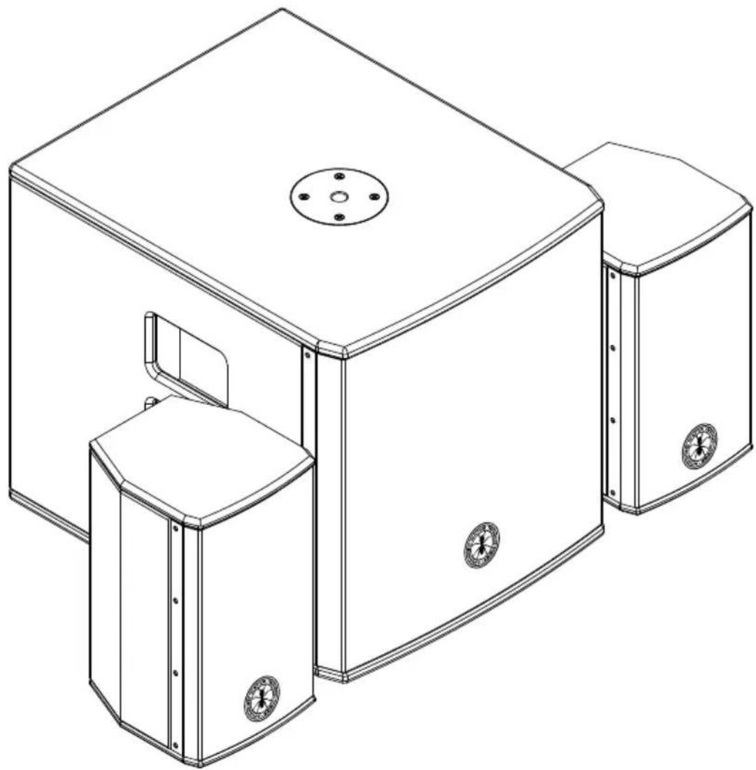
natural_image
Technical line drawing of a three-tiered industrial enclosure with mounting flanges and a central circular vent (no text or symbols)BHS SERIES
COMPACT ACTIVE 2.1 SYSTEMS
SISTEMI ATTIVI COMPATTI 2.1
SYSTÈMES ACTIFS COMPACTS 2.1
AKTIVE KOMPAKTSYSTEME 2.1
SISTEMAS ACTIVOS COMPACTOS 2.1
BHS 800 | BHS 1200 | BHS 1800
ES MANUAL DE USO | SECCION 1
IT MANUALDE D'USO | SEZIONE 1 DE BIDLENUGSALUTUNG | KAPITEL 1
FR NOTICE D:\EMPL01 | SECTION 1
IT MANUALE D'USO | SEZIONE 1
BHS SERIES
TABLE OF CONTENTS
1 | Introduction 4
2 | Installation 4
3 | Description 6
3.1 | Inputs & Controls 6
3.2 | Power supply 11
4 | Instructions for system assembly and disassembly 13
5 | Troubleshooting 16
6 | Technical specifications 17
7 | Notes 19
PACKAGE CONTENT - BHS 800
- 1 x BHS 800S bandpass active subwoofer including:
- n.1 mains cord (VDE)
- n.2 SpeakON cables
• n.2 passive full-range speakers BHS 800T
• 1x User manual - Section 1
• 1x User manual - Section 2
natural_image
Technical line drawings of two electrical equipment units with labeled components and a separate plug symbol (no text or labels present)The warnings in this manual must be observed together with the "USER MANUAL - SECTION 2".

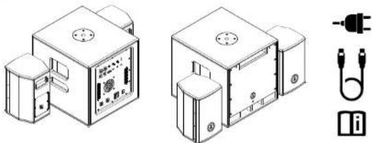
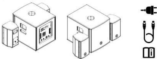
PACKAGE CONTENT - BHS 1200
• 1 x BHS 1200S active subwoofer including:
- n.1 mains cord (VDE)
- n.2 SpeakON cables
1 x Kit BHS 1200T in a separate package, including:
- n.2 passive full-range speakers BHS 1200T
1x User manual - Section 1
1x User manual - Section 2
natural_image
Technical line drawings of two electrical connectors with terminal blocks and a plug symbol (no text or labels)PACKAGE CONTENT - BHS 1800
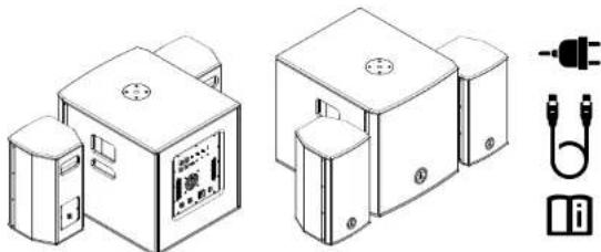
• 1 x BHS 1800S active subwoofer including:
- n.1 mains cord (VDE)
- n.2 SpeakON cables
• 1 x Kit BHS 1800T in a separate package, including:
- n.2 passive full-range speakers BHS 1800T
• 1x User manual - Section 1
• 1x User manual - Section 2
natural_image
Technical line drawings of two electronic device enclosures with labeled components (no text or symbols present)BHS Series | User manual
BHS SERIES
1 | INTRODUCTION
Thank you for choosing a A.N.T - Advanced Native Technologies - product! In BHS systems we have put our passion and our technological background gained over the years, to offer products that meet your needs, maintaining the quality over time. Specifically designed for an immediate and user-friendly application, meeting the needs of those who are looking for an audio system delivering excellent performances, high connection versatility as well as the best value in its category. Characterized by an elegant and contemporary profile, these systems perfectly combines great quality professional features and exceptional value such as:
- Wide range of input, allowing the use in several application configurations.
• Independent MAIN and SUB levels; - Phase control for perfect low/high balance in any environment;
• STEREO/MONO selector; - Excellent power/dimensions ratio, optimizing transport and installation.
A series of optional accessories is available, making easy the transport, the mounting as well as warranting product integrity.
For further information about all A.N.T products catalog, please visit our website: www.ant-intomusic.com
2 | INSTALLATION
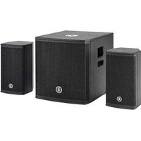
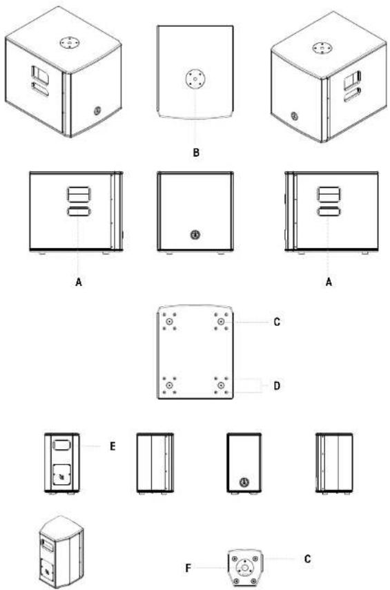
Each system is composed by an active subwoofer and two passive speakers:
A | Sub side recessed handle.
B | M20 flange for pole installation.
C | Anti-slip rubber feet.
D | Built-in fastening points for transport wheels fixing.
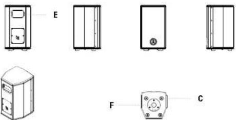
E | Rear recessed handles for passive speakers.
F | 36mm flange for pole installation.
4 User manual | BHS Series

DO NOT USE THE HANDLES TO HANG THE SPEAKERS!
BHS Series | User manual

3 | DESCRIPTION
3.1 | INPUTS & CONTROLS
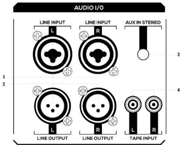
text_image
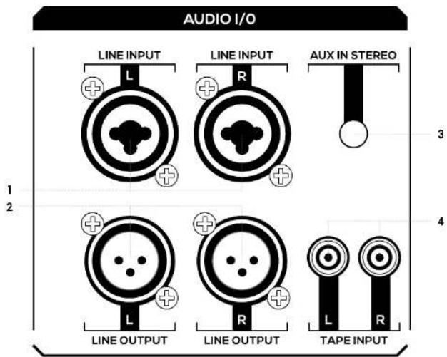
AUDIO I/O LINE INPUT LINE INPUT AUX IN STEREO 1 2 3 4 LINE OUTPUT LINE OUTPUT TAPE INPUT1 LINE INPUT L/R
Balanced line level inputs, with COMBO (XLR-F + 6,35mm. socket) connectors; by connecting one cable to L (MONO) input, the signal is internally processed as mono. These inputs level is adjusted by MAIN LEVEL knob. Anyway both inputs allows the connection by unbalanced cables.
NOTE: Please try to always use balanced cables. In any case, don't use a balanced cable for one channel and an unbalanced cable for the other channel.
2 LINE OUTPUT L/R
Linking outputs of the respective LINE INPUT L/R signals on XLR-M sockets. The signals of these outputs depend on the setting of the MAIN LEVEL knob.
text_image
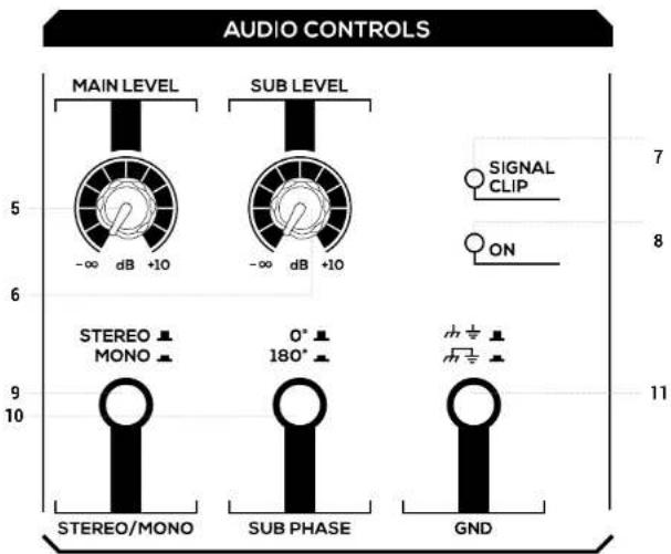
AUDIO CONTROLS MAIN LEVEL SUB LEVEL -∞ dB +10 5 6 9 10 STEREO MONO 0° 180° GND 7 8 113 AUX IN STEREO
This 3.5mm. stereo input accepts the signal cable from external devices, such as a smartphone, tablet, PC or any other device with a stereo mini-jack output.
4 TAPE INPUT L/R
Unbalanced stereo line input with RCA L/R sockets. Connect the output of a hi-fi device (CD player) or other device with RCA L/R outputs to these sockets. The volume of this stereo input is adjusted via the MAIN LEVEL knob.
BHS SERIES
5 MAIN LEVEL
This control adjusts the output volume of the system. Turn the knob clockwise to increase the volume or counterclockwise to lower it. For optimal adjustment always evaluate the acoustics of the environment and the musical genre.
6 SUB LEVEL
This control adjusts the output volume of the subwoofer and allows you to balance the low frequency level, based on the acoustics of the venue. Turn the knob clockwise to increase the subwoofer volume or counterclockwise to decrease it.
7 SIG/CLIP LED
Green LED: the signal is present in MAIN channel. Red LED: the input signal is very strong and it's close to distortion. If the red LED flashes continuously it's necessary to reduce the MAIN LEVEL or reduce the levels of the devices connected to the LINE / AUX / TAPE inputs.
CAUTION: the system must never work with levels causing the CLIP red LED to light up almost constantly.
8 ON LED
This switch allows to select the system listening configuration in two different modes: STEREO or MONO.
- Place the switch on MONO when connecting one cable to LINE INPUT L only, or when you desire to listen in MONO; in this case all stereo signals present in inputs are internally summed.
- Place the switch on STEREO when you use the system in a standard configuration; in this case all the stereo signals present in inputs are addressed to respective right and left speaker.
10 SUB PHASE (0°-180°)
Press this switch to invert by 180 degrees subwoofer phase, thus compensating any phase cancellation due to venue acoustic, presence of more subwoofers or to satellites with non-standard phase.
11 GND
Press this switch to reduce or eliminate electrical ground noise when connecting signal lines between several appliances. It is very effective for eliminating ground loops, but the actual result depends also on other connected devices.
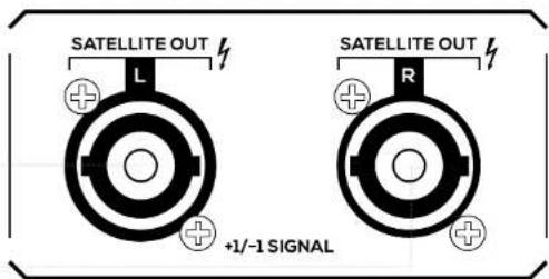
12 SATELLITE OUT L/R
Power outputs on 2-pole SpeakON connector for connection to the speakers.
Use the SpeakON cables supplied with the system to send the signal to left and right speakers.
CAUTION: Do not connect other speakers with different impedance to these outputs. The use of speakers not suitable for the amplifier's load capacity can irreversibly damage the unit.
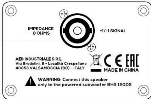
13 SATELLITE INPUT L/R
Speaker input on 2-pole SpeakON connector. These inputs must be connected to the SATELLITE OUT power output of the corresponding left or right channel.
12
text_image
SATELLITE OUT L +1/-1 SIGNAL SATELLITE OUT R13
text_image
IMPEDANCE 8 OHMS +1/-1 SIGNAL AEB INDUSTRIALE S.R.L Via Brodolini, 8 - Località Crespeliano 40053 VALSAMOGGIA (BO) - ITALY CE EAC MADE IN CHINA WARNING: Connect this speaker only to the powered subwoofer BHS 1200S
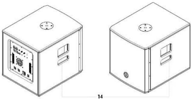
14 SIDE RECESSED HANDLE - SUBWOOFER
Use these handles (Fig.1) for transporting and positioning the subwoofer. Do not use them to fly the subwoofer or to lock it in any position.
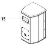
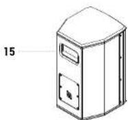
15 REAR RECESSED HANDLES - SPEAKERS
Use this handle to transport and position the system satellites. Do not use them to fly the speakers on the wall, the ceiling or to lock in any position the satellites.
Fig.1 - Transport handles - Subwoofer
natural_image
Technical line drawing of two 3D box units with internal components and mounting holes, no text or symbols present.Fig.2 - Transport handles - Satellite speaker
3.2 | POWER SUPPLY
1
MAINS
INPUT:
220-240V\~
50-60Hz
FUSE:
T4AL 250V\~
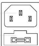
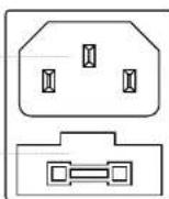
IEC mains socket with integrated EMI filter. Each package is supplied with the necessary power cord, specific for your area. Insert the mains cable into this socket, but make sure the system is switched off before connecting the cable to the mains. For your safety, never disconnect the ground lead.
WARNING!

Never remove the front protection grille. To prevent the risk of electric shock, in case of accidental damage or replacement of the protection grille (to be carried out by service centers only), immediately disconnect the power supply.

CAUTION: To reduce the risk of electric shock, never connect the power supply to the appliance while the grille is removed.
2 FUSE
Protection fuse integrated in mains socket.

CAUTION: Replace the fuse only with one of the same type and with the same value. If the fuse blows repeatedly, contact an authorized service center.
3 POWER ON/OFF
Use this switch to turn ON/OFF the system. NOTE: For proper operation always switch on the system last and switch it off first. Before turning on the system, make sure the MAIN LEVEL knob is at minimum.
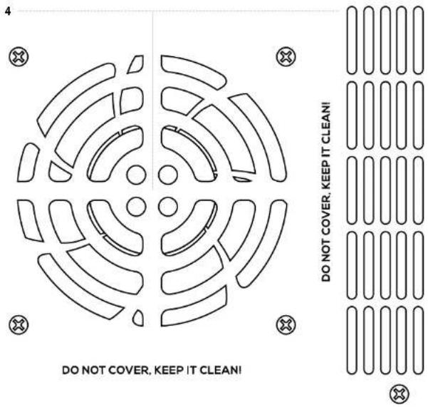
4 COOLING FAN AND VENTILATION SLOTS
If prThe cooling process of the amplifier and temperature control within laws limits are ensured by proper ventilation of the system, thus it's recommended to don't obstruct or cover in any way subwoofer rear cabinet ventilation slots.
text_image
DO NOT COVER, KEEP IT CLEANI DO NOT COVER, KEEP IT CLEANI4 | INSTRUCTIONS FOR SYSTEM ASSEMBLY AND DISASSEMBLY
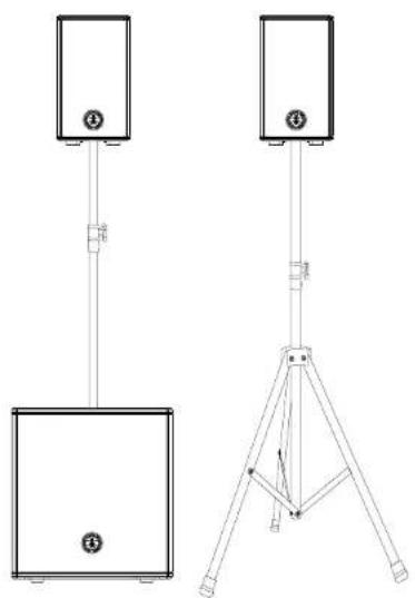
For system installation and to guarantee the correct operation, always carefully respect following instructions:
- Place the subwoofer in a vertical position on a flat and stable surface, making sure that all the rubber feet are perfectly adherent to the floor or to the supporting surface.
- Never install the system on mobile carts, chairs, tables or similar surfaces which are not stable and cannot bear the weight.
- To allow proper amplification heat dissipation, please leave the needed distance between the rear panel of the subwoofer and other objects such as walls, corners, curtains. Never place the unit near heat sources of any kind.
- Do not cover the ventilation slots located on subwoofer rear cabinet.
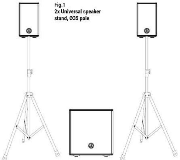
text_image
Fig.1 2x Universal speaker stand, Ø35 poleBHS SERIES
Fig.2
1x Universal speaker stand, 035 pole +
1x Sub-sat telescopic pole, thread M20 / ∅35
natural_image
Technical line drawing of two outdoor lighting equipment setups with standers and a tripod mount (no text or symbols)14 User manual | BHS Series
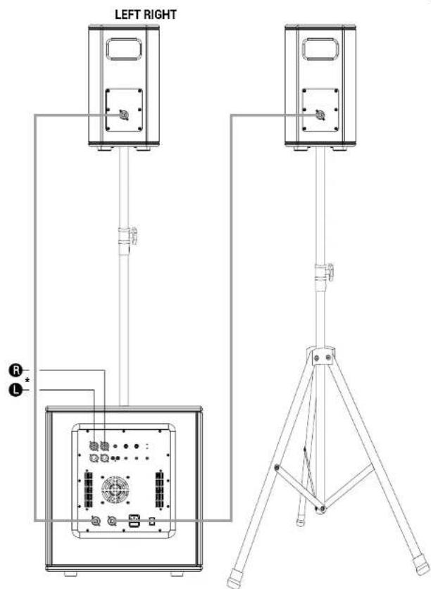
text_image
LEFT RIGHT R L*ANTIMIX SERIES MIXER
BHS Series | User manual

5 | TROUBLESHOOTING
| PROBLEM LED | SOLUTION | |
| No sound or very low sound level | Power LED turned off. | Make sure the system is properly connected to the mains outlet. Make sure that mains plug is firmly inserted into the socket. |
| Power LED turned on, but low MAIN LEVEL. | Turn the MAIN LEVEL knob clockwise.Make sure the SIG LED is on.Check the signal cable. | |
| Distortion | SIG/CLIP ^2 LED lit red. | Lower inputs and/or MAIN LEVEL knob. |
| Led SIG/CLIP verde | Controllate it livello della sorgente.Controllate la perfetta connessione fra subwoofer e i satellit.. | |
| Booming sound | Lower SUB level.Check satellites connections. | |
| Harsh sound | Raise SUB level.Lower MAIN LEVEL knob. | |
| Noise / hum | Activate the GND LIFT switch on subwoofer back panel, if the problem remains, press the GND LIFT switches of all the amplifiers/devices connected to the system. | |
| Use only balanced cables, avoid using unbalanced cables.Try to connect your entire system under the same electric current line, so that all the equipment shares the same AC Ground. |
6 | TECHNICAL SPECIFICATIONS
| BHS 800 BHS 1200 BHS 1800 | |||
| Subwoo'er(BHS 800S / BHS1200S / BHS 1800S) | Band-pass cabinet8" custom ferritewoo'er - 1.5" VC | Bass reflex cabinet12" custom ferrite- 2.5" VC | Bass reflex cabinet15" custom ferrite- 2.5" VC |
| Satellite(800T / 1200T /1800T) | 2-way, full rangeLF: 0°/11F: 1"horn loaded tweeter | 2-way, full rangeLF: 6.9"/11F: 1"horn loaded driver | 2-way, full rangeLF: 3°/11F: 1"horn loaded driver |
| Satellites dispersion(lift xV) | 100 x 60 90 x 60 80 x 60 | ||
| Frequency response(fentire system) | 60Hz-20kHz 60Hz-20kHz 42Hz-20kHz | ||
| MAX SPL 120dB 124cB 126cB | |||
| Amplification D Class D Class D Class | |||
| System peak power 800 W 1200 W 1800 W | |||
| Crossover slope andfrequency | 24dB/0ct @ 200Hz 24dB/0ct @180Hz 24dB/0ct @ 140Hz | ||
| Input and outputconnectors | 2 x COMBO (XLR-F+ 2 x jack 6.35mm,1/4") AUX IN: 1 xmini-jack 3.5mmTAPE IN: RCA L/RLINE OUTPUT:2 x XLR MSATELLITE OUT:2 x SPEAKON | 2 x COMBO (XLR-F+ 2 x jack 6.35mm,1/4") AUX IN: 1 xmini-jack 3.5mmTAPE IN: RCA L/RLINE OUTPUT:2 x XLR MSATELLITE OUT:2 x SPEAKON | 2 x COMBO (XLR-F+ 2 x jack 6.35mm,1/4") AUX IN: 1 xmini-jack 6.5mmTAPE IN: RCA L/RLINE OUTPUT:2 x XLR MSATELLITE OUT:2 x SPEAKON |
| Controls | Main Level, Sublevel, 0°-190°phase reverse,STEREO/MONOSwitch, GND andON/OFF switches | Main Level, Sublevel, 0°-180°phase reverse,STEREO/MONOSwitch, GND andON/OFF switches | Main Level, Sublevel, 0°-180°phase reverse,STEREO/MONOSwitch, GND andON/OFF switches |
| Protections | Short circuit,over-current,Dual-limiter | Short circuit,over-current,Dual-limiter | Short circuit,over-current,Dual-limiter |

BHS SERIES
| BHS 800 BHS 1200 | BHS 1800 | ||
| Cooling Fan Fan Fan | |||
| Operating mains 220-240V~50-60Hz 220-240V~50-60Hz | |||
| Fuse T4A L 250V~T4A L 250V~T4A L 250V~ | |||
| Max power consumption | 400 W 500 W 900 W | ||
| Subwoofer cabinet material | 12mm high-density MDF | 15mm Plywood 16mm Plywood | |
| Satellite cabinet material | 12mm high-density MDF | 12mm high-density MDF | 12mm high-density MDF |
| Cabinets finishing | Anti-scratch paint with high mechanical resistance | Anti-scratch paint with high mechanical resistance | Anti-scratch paint with high mechanical resistance |
| Subwoofer dimension (W x H x D) | 370 x 380 x 416 mm 441 x 465 x 544 mm 482 x 520 x 588 mm | ||
| Satellite unity dimensions (W x H x D) | 180 x 290 x 193.5 mm 200 x 345 x 215 mm 240 x 435 x 250 mm | ||
| Subwoofer net weight | 16 Kg 23 Kg 29 Kg | ||
| Satellite unity net weight | 3.5 Kg 5 Kg 5.7 Kg | ||
| Optional accessoriesw | Sub / Sat cover kit | Sub / Sat cover kit Wheels kt (SUB only) | Sub / Sat cover kit Wheels kt (SUB only) |
7 | NOTES

BHS SERIES
INDICE
natural_image
Technical line drawings of two electrical enclosure units with labeled components and a separate plug symbol (no text or labels present)natural_image
Technical line drawings of two electrical connectors with terminal blocks and a plug symbol (no text or labels)CONTENUTO DELL'IMBALLO - BHS 1800
natural_image
Technical line drawings of two electronic device enclosures with labeled components (no text or symbols present)Serie BHS | Manuale d'uso

BHS SERIES

1 | INTRODUZIONE
natural_image
Technical line drawing of two 3D box units with internal components and mounting holes, no text or symbols present.text_image
DO NOT COVER, KEEP IT CLEANI DO NOT COVER, KEEP IT CLEANI4 | ISTRUZIONI DI MONTAGGIO E SMONTAGGIO DEL SISTEMA
natural_image
Technical line drawing of two outdoor lighting equipment setups with standers and a tripod mount (no text or symbols)32 Manuale d'uso | Serie BHS
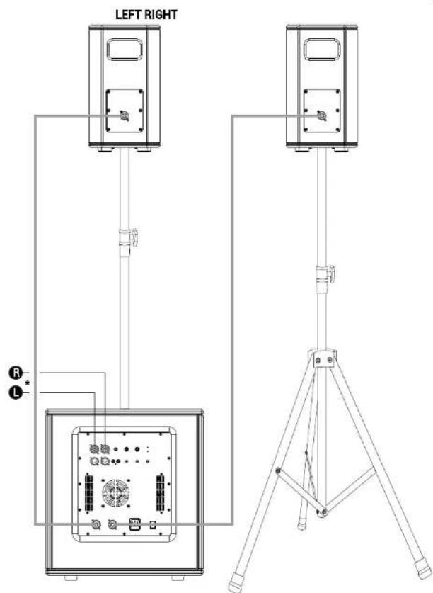
text_image
LEFT RIGHT R L*ANTIMIX SERIES MIXER
Serie BHS | Manuale d'uso

natural_image
Technical line drawings of two electronic devices with labeled ports and connectors (no text or symbols present)natural_image
Technical line drawings of two electrical connectors with terminal blocks and a plug symbol (no text or labels)CONTENU DE L'EMBALLAGE - BHS 1800
natural_image
Technical line drawings of two electrical enclosure units with mounting holes and a fuse, plus a separate plug symbol (no text or labels present)natural_image
Four simple line drawings of a refrigerator with labeled front panel (E), side panels, and door handle (no text or symbols on the diagrams themselves)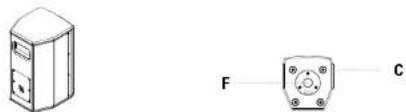
natural_image
Two technical diagrams showing a device with labeled points F and C, no readable text or symbols present.
N'UTILISEZ PAS LES POIGNÉES
POUR SUSPENDRE LES ENCEINTES !
3 | DESCRIPTION
3.1 | ENTRÉES & CONTRÔLES
text_image
AUDIO I/O LINE INPUT LINE INPUT AUX IN STEREO 1 2 3 4 LINE OUTPUT LINE OUTPUT TAPE INPUT1 LINE INPUT L/R
natural_image
Technical line drawing of two identical rectangular electronic devices with control panel and buttons, shown from top and side views (no text or symbols)text_image
DO NOT COVER, KEEP IT CLEAN! DO NOT COVER, KEEP IT CLEAN!4 | INSTRUCTIONS DE MONTAGE ET DE DÉMONTAGE DU SYSTÈME
natural_image
Technical line drawing of two outdoor lighting equipment setups with standers and a tripod mount (no text or symbols)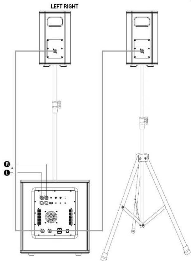
text_image
LEFT RIGHT R L*ANTIMIX SERIES MIXER
Serie BHS | Notice d'emploi
5 | DÉPANNAGE
natural_image
Technical line drawing of a mechanical housing or enclosure with mounting holes and internal components (no text or symbols)
natural_image
Isometric line drawing of a mechanical device with no visible text or symbols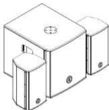
natural_image
Isometric line drawing of a mechanical housing or enclosure with mounting holes and a central circular feature (no text or symbols)
BHS SERIES

1 | EINFÜHRUNG
13 SATELLIT INPUT L/R
natural_image
Technical line drawing of two views of a box device with control panel and buttons (no text or symbols)text_image
DO NOT COVER, KEEP IT CLEANI DO NOT COVER, KEEP IT CLEANI4 | ANLEITUNGEN ZUR MONTAGE UND DEMONTAGE DES SYSTEMS
natural_image
Technical line drawing of two outdoor lighting equipment setups with standers and a tripod mount (no text or symbols)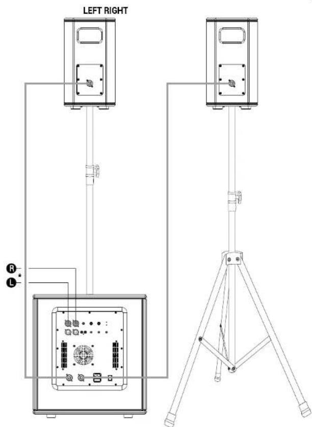
text_image
LEFT RIGHT R L* ANTIMIX SERIES MIXER
BHS Serie | Bedienungsanleitung
5 | FEHLERBEHEBUNG
natural_image
Technical line drawings of two electrical equipment units with labeled components and a separate plug symbol (no text or labels present)natural_image
Technical line drawing of two 3D box units with internal components and mounting holes, no text or symbols present.Fig.2 - Asa de transporte - Difusores
3.2 | ALIMENTACIÓN
1
MAINS
INPUT:
220-240V\~
50-60Hz
FUSE:
T4AL 250V\~
text_image
DO NOT COVER, KEEP IT CLEANI DO NOT COVER, KEEP IT CLEANI4 | INSTRUCCIONES PARA MONTAR Y DESMONTAR EL SISTEMA
natural_image
Technical line drawing of two outdoor lighting equipment setups with standers and a tripod mount (no text or symbols)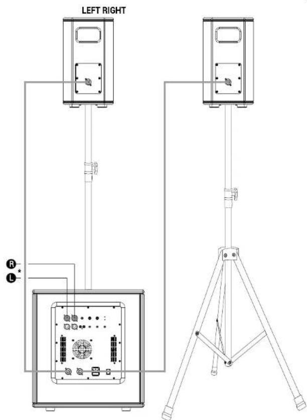
text_image
LEFT RIGHT R LENG The information contained in this manual have been carefully drawn up and checked. However no responsibility will be assumed for any incorrectness. This manual cannot cover all the possible contingencies which may arise during the product installation and use. Should further information be desired, please contact us or our local distributor A.E.B. industry Srl can not be considered responsible for damages which may be caused to people and things when using this product. Specifications and features are subject to change without prior notice.
ENG - Download this manual in other languages on www.ant-intomusic.com