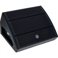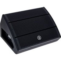
ASM 15 - Speaker ANT - Free user manual and instructions
Find the device manual for free ASM 15 ANT in PDF.


User questions about ASM 15 ANT
0 question about this device. Answer the ones you know or ask your own.
Ask a new question about this device
Download the instructions for your Speaker in PDF format for free! Find your manual ASM 15 - ANT and take your electronic device back in hand. On this page are published all the documents necessary for the use of your device. ASM 15 by ANT.
USER MANUAL ASM 15 ANT
text_image
ADVANCED NATIVE TECHNOLOGIES - ADVANCED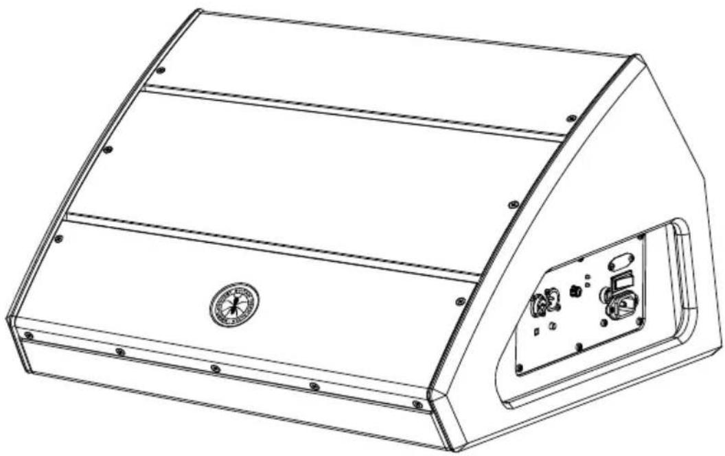
natural_image
Line drawing of a mechanical device casing with internal components and mounting holes (no text or symbols)ASM SERIES
ACTIVE COAXIAL STAGE MONITORS MONITOR DA PALCO ATTIVI COASSIALI MONITEURS DE SCÈNE ACTIFS COAXIAUX AKTIVE KOAXIAL-BÜHNEN MONITORE MONITORES ACTIVOS COAXIALES DE ESCENARIO ASM 10 | ASM 12 | ASM 15
EN USER MANUAL | SECTION 1 FR NOTICE D'EMPOUI | SECTION 1 ES MANUAL DE USO | SECTION 1
IT MANUALDE D'USO | SEZIONE 1 DE BIDLENUGSALUTUNG | KAPITEL 1
ASM SERIES
TABLE OF CONTENTS
| 1 | Introduction | 3 |
| 2 | Installation | 4 |
| 3 | Description | 5 |
| 3.1 | Inputs & controls 5 | |
| 3.2 | Power supply 8 | |
| 4 | Troubleshooting | 9 |
| 5 | Technical specifications 10 | |
| 6 | Notes | 52 |
CONTENUTO DELL'IMBALLO
• 1 x active coaxial stage monitor
- n.1 mains cord (VDE)
• 1x User manual - Section 1
• 1x User manual - Section 2
The warnings in this manual must be observed together with the
"USER MANUAL - SECTION 2"
ASM SERIES
2 | INSTALLATION
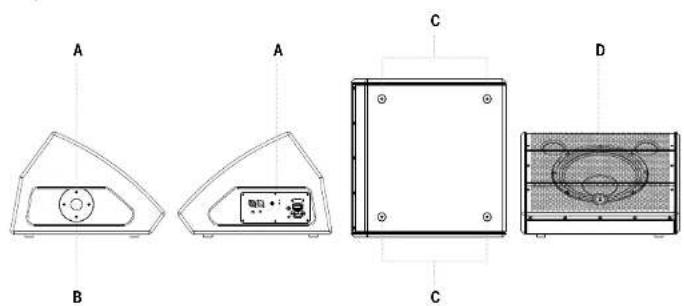
Each speaker is equipped with:
A | Recessed side handles
B | ∅ 35mm. flange for pole mounting
C | Non-slip rubber feet
D | Front metal protection grille
text_image
A A C B C DFor speaker installation and to guarantee its correct performance, strictly follow the instructions below:
- Place the speaker in a horizontal position on a flat and stable surface, making sure that all the lower rubber feet are perfectly adhering to the floor or to the supporting surface. The speaker is designed for use on the floor (wedge monitor configuration).
- Never install the speaker on mobile carts, chairs, tables or similar objects that are not stable or unable to withstand the weight.
• To allow for proper heat dissipation of the amplification, leave sufficient distance between the rear panel of the speaker and other objects such as walls, corners, curtains, and never place the appliance near sources of heat of any kind. - When used outdoors, avoid places exposed to bad weather.

CAUTION: Install the speaker in a stable and safe way, so as to avoid any dangerous condition for the safety of people and structures.

3 | DESCRIPTION
3.1 | INPUTS & CONTROLS
text_image
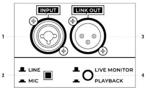
INPUT LINK OUT 1 3 2 LINE MIC LIVE MONITOR PLAYBACK 41 LINE INPUT L/R
Balanced line level inputs, with COMBO (XLR-F + 6,35mm. socket) connectors. You can also use an unbalanced mic cable. The inputs level is adjusted by LEVEL knob. NOTE: Please try to always use balanced cables.
2 LINE / MIC BUTTON
Place the button on LINE (up) to use a line level source (mixer and pre-amplified devices) or MIC (pressed) for using a microphone. To lower or raise it, use a screwdriver with a small flat head.
3 LINK OUT
Link output of input signal on XLR-M plug. The signal of this output depends on the setting of the LEVEL knob.
4 LIVE MONITOR / PLAYBACK BUTTON
Press this button to select the optimal equalization for using the speaker. It is possible to select the equalization setting between two different presets:
ASM SERIES
LIVE MONITOR
Perfect for live performances with the speaker positioned on the ground as a wedge stage monitor. Suitable for musicians and singers.
PLAYBACK
It emphasizes the low and high frequencies, and is ideal for listening and using reproduced music (MP3 players, CDs etc.), both for use as a main system mounted on a tripod but also as a reinforcement monitor.
text_image
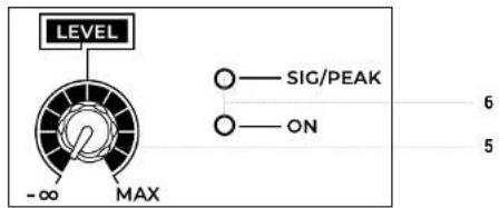
LEVEL -∞ MAX SIG/PEAK ON 6 55 LEVEL
This control adjusts the speaker output volume. Turn the knob clockwise to increase the volume or counterclockwise to lower it. For optimal adjustment always consider the acoustics of the environment and the musical genre.
6 INDICATORS ON & SIG / CLIP
Led ON: the unit is powered.
SIG/CLIP Green LED: the signal is present in the MIC/LINE INPUT channel. In normal operation the LED acts as a Vu meter indicating the audio level.
SIG/CLIP Red LED: the input signal is very high and is close to distortion. If the red LED lights up continuously, it's necessary to reduce the LEVEL level or reduce the levels of the devices connected to the MIC / LINE INPUT input.
CAUTION: the unit must never work with levels causing the SIG/CLIP LED to flash red almost constantly.
7 REAR PANEL
The cooling process of the amplifier and temperature control within laws limits are ensured by proper ventilation of the system, thus it's recommended to don't obstruct or cover in any way the rear panel of the speaker.

text_image
NATIVO TECHN ADVISA ASM12 ACTIVE COAXIAL STAGE MONITOR7
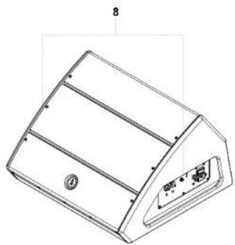
8 RECESSED HANDLES FOR LIFTING AND TRANSPORT
Use these recessed handles (Fig.1) for transporting and positioning the speaker. Do not use them to hang the speaker or to lock it in any position.
natural_image
Technical line drawing of a mechanical component with no visible text or symbolsFig.1 – Recessed handles for transport
ASM SERIES
3.2 | POWER SUPPLY
text_image
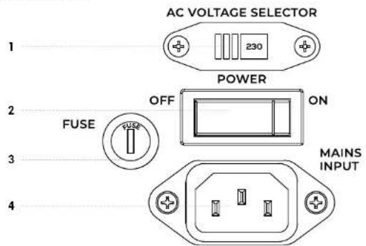
AC VOLTAGE SELECTOR 1 230 POWER OFF ON FUSE MAINS INPUT 3 41 AC VOLTAGE SELECTOR
Operating voltage selector. Generally it is not necessary to act on this command since it is set at the factory.
WARNING! Before switching on the unit, make sure that the mains voltage and that of the device match.
2 POWER ON/OFF
Use this switch to turn ON/OFF the system.
NOTE: For proper operation always switch on the system last and switch it off first. Before turning on the system, make sure the LEVEL knob is at minimum.
3 FUSE
Protection fuse.
CAUTION: Replace the fuse only with one of the same type and with the same values. If the fuse blows repeatedly, contact an authorized service center.
4 MAINS INPUT
IEC mains socket with integrated EMI filter. Each package is supplied with the necessary power cord, specific for your area. Insert the mains cable into this socket, but make sure the unit is switched off before connecting the cable to the mains. For your safety, never disconnect the ground lead..
CAUTION: To reduce the risk of electric shock, never connect the power supply to the appliance while the grille is removed.
4 | TROUBLESHOOTING
| PROBLEM LED SOLUTION | ||
| No sound | Power LED turned ofT | Make sure the system is properly connected to the mains outlet.Make sure that mains plug is firmly inserted into the socket. |
| very low sound level | Power LED turned on, but low MAIN LEVEL | Turn the MAIN LEVEL knob clockwise.Make sure the SIG LED is onCheck the signal cable |
| Distortion | SIG/CLIP LED lit red | Lower the level of LEVEL knob or input sources. When using input line signals, make sure that the LINE / MIC button is not pressed in the MIC position. |
| ON/LIMIT LED lit green | Check the source level. | |
| Booming sound | Put the selector in LIVE MONITOR positionCheck source signal. | |
| Harsh sound | Put the selector in PLAYBACK positionCheck source signal. | |

ASM SERIES
5 | TECHNICAL SPECIFICATIONS
| ASM10 ASM12 ASM15 | |||
| System 2-way vented box 2-way vented box 2-way vented box | |||
| LF Custom 10" Woofer, 2" VC | Custom 12" Woofer, 2.5" VC | Custom 15" Woofer, 3" VC | |
| HF I" compression driver, 1" VC | 1" compression driver, 1.35" VC | 1" compression driver, 1.35" VC | |
| Amplification Class-D + Class-A/B Class-D + Class-A/B Class-D + Class-A/B | |||
| Peak power (LF+HF) 400W 600W 600W | |||
| Frequency response (+/-10dB) | 70Hz-20kHz 65Hz-20kHz 55Hz-20kHz | ||
| MAX SPL 122dB 124dB 126dB | |||
| DSI" 562L | 56Bit | 56Bit | |
| AD/DA conversion | 24Bit / 48kHz | 24Bit / 48kHz | 24Bit / 48kHz |
| EQ 2 Presets 2 Presets 2 Presets | |||
| Input and output connectors | MIC/LINE COMBO(XLR F + 2 x jack6.35mm. 1/4")LINK output: XLR-M | MIC/LINE COMBO(XLR F + 2 x jack6.35mm. 1/4")LINK output: XLR-M | MIC/LINE COMBO(XLR F + 2 x jack6.35mm. 1/4")LINK output: XLR-M |
| Controls | LEVEL, LINE/MIC switchON PEAK/SIGN LEDsPRESET button | LEVEL, LINE/MIC switchON PEAK/SIGN LEDsPRESET button | LEVEL, LINE/MIC switchON PEAK/SIGN LEDsPRESET button |
| ASM10 | ASM12 | ASM15 | |
| Operating mainsFuse | 220-240V~50-60HzT2A L 250V~110-120V~50-60 HzT4A L 250V~ | 220-240V~50-60HzT2A L 250V~110-120V~50-60 Hz - T4A L 250V~ | 220-240V~50-60HzT2A L 250V~110-120V~50-60 HzT4A L 250V~ |
| Max power consumption | 300 W | 300 W | 300 W |
| Cabinet | 2 recessed handlesPole mount∅ 35mm. hole | 2 recessed handlesPole mount∅ 35mm. hole | 2 recessed handlesPole mount∅ 35mm. hole |
| Cabinet material | 15mm plywood | 15mm plywood | 15mm plywood |
| Cabinots finishing | Anti-scratch paint with high mechanical resistance | Anti-scratch paint with high mechanical resistance | Anti-scraton paint with high mechanical resistance |
| Dimensions(W x H x D) | 380 x 333 x 490 mm | 450 x 338 x 510 mm | 495 x 405 x 610 mm |
| Net weight 12 Kg | 19 Kg | 20.5 Kg | |
| Optional accessories | CV-SM10padded cover | CV-SM12padded cover | CV-SM15padded cover |

ASM SERIES
INDICE
6 INDICATORI ON & SIG/CLIP
natural_image
Technical line drawing of a 3D mechanical component with internal ribs and mounting holes (no text or symbols)natural_image
Technical line drawing of a mechanical component with labeled parts (no text or symbols present)natural_image
Technical line drawing of a 3D mechanical component with internal ribs and mounting holes (no text or symbols)natural_image
Technical line drawing of a mechanical component with no visible text or symbolsENG The information contained in this manual have been carefully drawn up and checked. However no responsibility will be assumed for any incorrectness. This manual cannot cover all the possible contingencies which may arise during the product installation and use. Should further information be desired, please contact us or our local distributor. A E.g. Industrie Srl can not be considered responsible for damages which may be caused to people and things when using this product. Specifications and features are subject to change without priorities.