
MIBS - Microphone LD Systems - Free user manual and instructions
Find the device manual for free MIBS LD Systems in PDF.
| Product type | Desktop microphone base with push-button |
| Controls | Push-button with 3 switchable modes: Push-to-Talk, Push-to-Mute, Toggle |
| Indicators | White status LED (microphone active) |
| Microphone compatibility | Dynamic and condenser (phantom power required) |
| Input | 1x 3-pin female XLR |
| Output | 1x 3-pin male XLR |
| Input impedance | 47 kΩ (balanced) |
| Output impedance | 800 Ω (balanced) |
| Frequency response | 90 Hz - 20 kHz (-3 dB) |
| Max. input voltage | 870 mV RMS |
| Mute attenuation | >75 dB @ 1 kHz |
| CMRR | >65 dB |
| Gain (48 V supply) | +5.5 dB |
| Power supply | Phantom 15-48 V DC, 6 mA typical |
| Consumption (Mute) | 3 mW |
| Operating temperature | 0 °C to 40 °C |
| Relative humidity | <85% (non-condensing) |
| Housing material | Zinc, plastic front panel |
| Color | Black |
| Dimensions (W x H x D) | 109.8 x 38.7 x 126.2 mm |
| Weight | 0.54 kg |
| Use | Indoor only, fixed professional installation |
| Safety | Do not open, keep out of reach of children, small parts |
| Cleaning | Dry, soft cloth |
Frequently Asked Questions - MIBS LD Systems
User questions about MIBS LD Systems
0 question about this device. Answer the ones you know or ask your own.
Ask a new question about this device
Download the instructions for your Microphone in PDF format for free! Find your manual MIBS - LD Systems and take your electronic device back in hand. On this page are published all the documents necessary for the use of your device. MIBS by LD Systems.
USER MANUAL MIBS LD Systems
natural_image
Black rectangular electronic device with a circular button and metallic connector (no visible text or symbols)MIBS
MICROPHONE DESKTOP BASE WITH CONFIGURABLE SWITCH LDMIBS
CONTENTS / INHALTSVERZEICHNIS / CONTENU / CONTENIDO / TREŚĆ / CONTENUTO
ENGLISH
INTENDED USE 4
SAFETY INFORMATION 4
INTRODUCTION 5
COMPONENTS, CONNECTIONS, DISPLAYS AND CONTROLS 5
WIRING EXAMPLE 6
TECHNICAL DATA 7
DISPOSAL 8
MANUFACTURER'S DECLARATIONS 9
DEUTSCH
VERWENDUNGSZWECK 10
We have designed this product to operate reliably over many years. LD Systems stands for this with its name and many years of experience as a manufacturer of high-quality audio products. Please read this User's Manual carefully, so that you can begin making optimum use of your LD Systems product quickly. You can find more information about LD SYSTEMS at our Internet site WWW.LD-SYSTEMS.COM
INTENDED USE
The product is a device for professional audio installation!
The product has been developed for professional use in the field of audio installation and is not suitable for use in households!
Furthermore, this product is only intended for qualified users with specialist knowledge of dealing with audio installations!
Use of the product outside of the specified technical data and operating conditions is considered improper use!
Liability for damage and third-party damage to persons and property due to improper use is excluded!
The product is not suitable for:
- People (including children) with reduced physical, sensory or mental abilities or lack of experience and knowledge.
- Children (Children must be instructed not to play with the device).
SAFETY INFORMATION
- Please read these instructions carefully.
- Keep all information and instructions in a safe place.
- Follow the instructions.
- Use the appliance only in the manner intended.
- Do not open or modify the unit.

CAUTION: Connecting signal cables can lead to considerable noise interference. Make sure that the input channel of e.g. an installation mixer is muted when plugging a device in. Otherwise, these noise levels might cause damage.
DANGER OF SUFFOCATION! KEEP AWAY FROM CHILDREN! THE PRODUCT CONTAINS SMALL PARTS THAT CAN BE SWALLOWED AND PACKAGING MATERIAL THAT CAN BE SWALLOWED! PLASTIC BAGS MUST BE KEPT OUT OF REACH OF CHILDREN!
INTRODUCTION
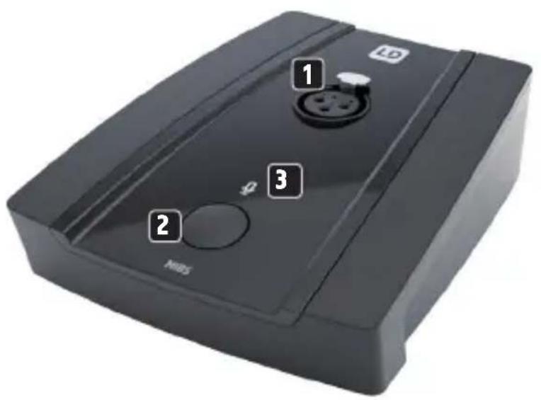
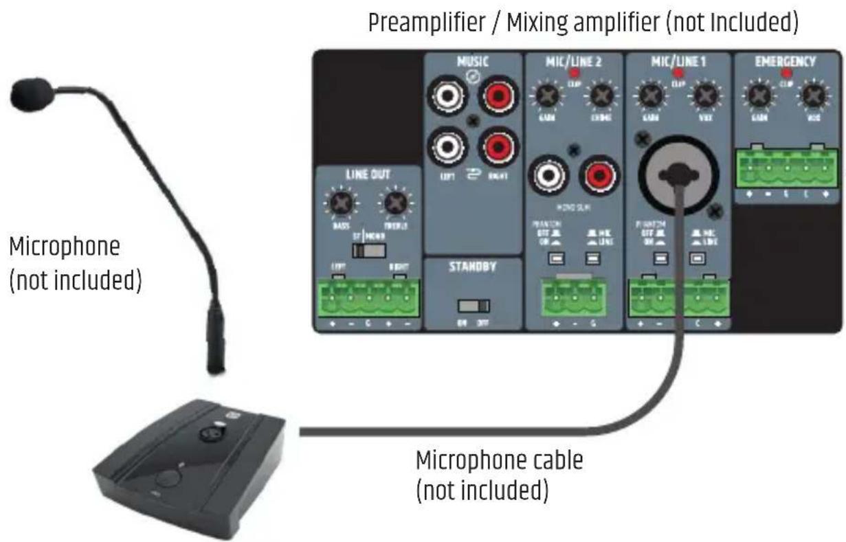
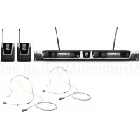
The LD MIBS solid microphone base features a female XLR connector, a push button and an illuminated status indicator on the top, a male XLR connector on the rear and an operating mode selector switch on the bottom. Phantom power is required for operation. The microphone base is suitable for both dynamic and condenser microphones.
COMPONENTS, CONNECTIONS, DISPLAYS AND CONTROLS
natural_image
Close-up of a black electronic device component with a central pin and three dots, labeled with number 4 (no text or symbols on the device itself)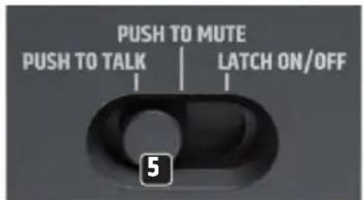
1 Female 3-pin XLR connector for connecting a microphone.
2 Push-button with multiple functions (see item 5 Operating mode selector switch).
3 Microphone symbol with illumination to indicate the operating status. The microphone symbol lights up white when the microphone is active.
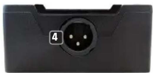
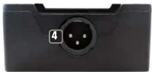
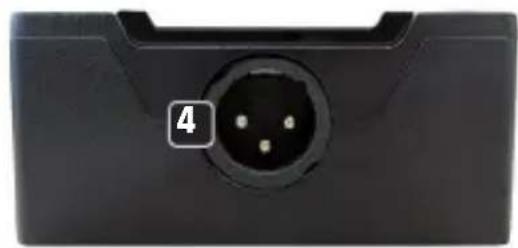
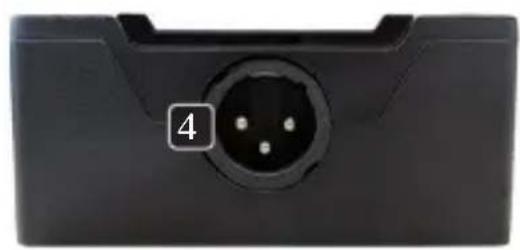
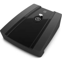
4 Male 3-pin XLR socket for connecting the microphone signal to an installation mixer or similar.
5 The operating mode selector switch is located on the underside of the base.
PUSH TO TALK
The microphone is only active as long as you press the button 2. To mute the microphone, release the button.
PUSH TO MUTE
The microphone is permanently active and is only muted as long as the button 2 is pressed.
LATCH ON/OFF
Push-button 2 with switch function. Press the button briefly to activate the microphone and again briefly to mute it.
WIRING EXAMPLE
TECHNICAL DATA
Article number LDMIBS
Product type Desktop microphone base with push-button
Controls Push-button with 3 selectable modes, mode selector switch: PUSH TO TALK / PUSH TO MUTE / LATCH ON/OFF
Display elements Status LED (lights up white when the microphone is active)
Maximum input voltage 870 mV RMS
Frequency response 90 Hz - 20 kHz (-3 dB)
Input impedance 47 kohms (balanced)
Output impedance 800 ohms (balanced)
Mute damping > 75 dB @ 1 kHz
CMRR > 65 dB (CMRR IEC)
Gain @ 48 V phantom power IN vs. OUT 5.5dB
Inputs 1x 3-pole XLR female
Outputs 1x 3-pole XLR male
Phantom power requirements 15 VDC - 48 VDC (±10%), 6 mA typical
Power consumption (mute) 3 mW (microphone muted)
Power consumption 6 mA
Operating temperature 0^ C - 40^ C
Relative humidity < 85%, non-condensing
General
Material Zinc housing, plastic front panel
Colour Black
Dimensions (W x H x D) 109.8mm x 38.7mm x 126.2mm (height with rubber feet)
Weight 0,54 kg
DISPOSAL

PACKAGING:
- Packaging can be disposed of via the usual waste disposal channels.
- Please separate the packaging according to the waste disposal and materials regulations in your country.
DEVICE:
-
This device is subject to the European Directive on Waste Electrical and Electronic Equipment in its applicable version. WEEE Directive- Waste Electrical and Electronic Equipment. Old devices and batteries do not belong in household waste. The old device or batteries must be disposed of via an approved waste disposal service or a municipal waste disposal facility. Follow the directives in your country!
-
Follow the disposal laws in your country.
- As a private customer, you can obtain information on environmentally friendly disposal options from the retailer from whom you purchased the product or from the relevant regional authorities.
MANUFACTURER'S DECLARATIONS
MANUFACTURER'S WARRANTY & LIMITATION OF LIABILITY
Adam Hall GmbH, Adam-Hall-Str. 1, 61267 Neu Anspach, Germany
E-mail Info@adamhall.com / +49 (0)6081 / 9419-0.
Our current warranty conditions and limitation of liability can be found at:
https://cdn-shop.adamhall.com/media/pdf/MANUFACTURERS-DECLARATIONS_LD_SYSTEMS.pdf
Contact your distribution partner for service.
UKCA- CONFORMITY
Hereby, Adam Hall Ltd. declares that this product meets the following guidelines
(where applicable) Electrical Equipment (Safety) Regulations 2016
Electromagnetic Compatibility Regulations 2016 (SI 2016/1091)
The Restriction of the Use of Certain Hazardous Substances in Electrical
and Electronic Equipment
Regulation 2012 (SI 2012/3032)
Radio Equipment Regulations 2017(SI 2016/2015)
UKCA- DECLARATION OF CONFORMITY
Products that are subject to Electrical Equipment(Safety)Regulation 2016, EMC Regulation 2016 or
RoHS Regulation can be requested at info@adamhall.com. Products that are subject to the Radio
Equipments Regulations 2017 (SI2017/1206) can be downloaded from
www.adamhall.com/compliance/

FOR INDOOR USE ONLY
This symbol indicates electrical equipment designed primarily for indoor use.
Misprints and errors as well as technical or other changes are reserved!
DEUTSCH
natural_image
Close-up of a black electronic device component with a central pin and labeled section 4 (no text or symbols beyond the label)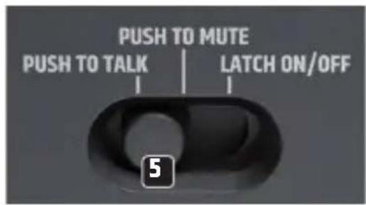
natural_image
Close-up of a black electronic component with a central pinout and a numbered label '4' (no text or symbols on the main body)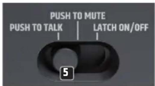
DÉCLARATION DE CONFORMITÉ CE

natural_image
Close-up of a black electronic device component with a central pin and numbered label (4) on the left side.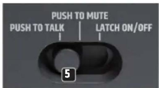
PUSH TO TALK, PUSH TO MUTE, LATCH ON/OFF
www.adamhall.com/compliance/.

SOLO PARA USO EN INTERIORES
natural_image
Close-up of a black electronic device component with a circular pinout and a numbered label '4' (no text or symbols on the main body)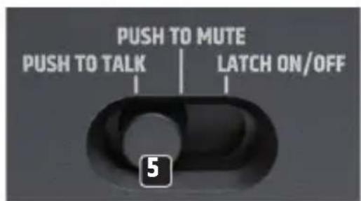
natural_image
Black rectangular electronic device with control buttons and a circular display (no visible text or symbols)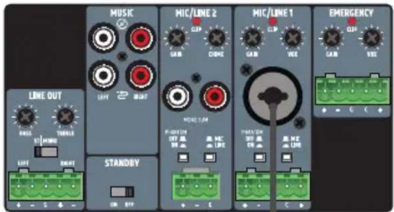
CMRR > 65 dB (CMRR IEC)
www.adamhall.com/compliance/.

natural_image
Close-up of a black electronic device component with a central pin and three small dots, labeled with number 4 (no text or symbols on the device itself)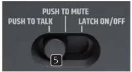
CMRR > 65 dB (CMRR IEC)
www.adamhall.com/compliance/.

SOLO PER USO IN INTERNI

- MIBS
- CONTENTS / INHALTSVERZEICHNIS / CONTENU / CONTENIDO / TREŚĆ / CONTENUTO
- ENGLISH
- DEUTSCH
- INTENDED USE
- SAFETY INFORMATION
- INTRODUCTION
- TECHNICAL DATA
- Article number LDMIBS
- General
- DISPOSAL
- PACKAGING:
- DEVICE:
- MANUFACTURER'S DECLARATIONS
- MANUFACTURER'S WARRANTY & LIMITATION OF LIABILITY
- UKCA- CONFORMITY
- UKCA- DECLARATION OF CONFORMITY
- FOR INDOOR USE ONLY
- DÉCLARATION DE CONFORMITÉ CE
- SOLO PARA USO EN INTERIORES
- SOLO PER USO IN INTERNI
Brand : LD Systems
Model : MIBS
Category : Microphone