
621444 - Bike accessory SILVERLINE - Free user manual and instructions
Find the device manual for free 621444 SILVERLINE in PDF.

| Product Type | Rear bike rack for vehicle |
| Brand | Silverline |
| Model | 621444 |
| Dimensions (L x W x H) | 750 x 515 x 95 mm |
| Weight | 2.5 kg |
| Maximum working load (MWL) | 45 kg |
| Maximum number of bikes | 3 adult bikes |
| Mounting type | Rear, on tailgate |
| Main materials | Steel frame, nylon straps, rubber-coated hooks |
| Supplied accessories | Frame, straps (1200 mm and 930 mm), hooks, locking loops, bike ties, fasteners |
| Vehicle compatibility | Cars with tailgate (except sports cars, convertibles, split or side-opening tailgates) |
| Recommended tilt angle | 20° upward from horizontal |
| Minimum distance from vehicle | 5 cm between carrier and bodywork |
| Intended use | Transport of adult bikes, do not exceed maximum load |
| Safety instructions | Do not attach lower straps to plastic parts; do not obstruct lights or license plate; regularly check strap tension |
| Maintenance | Clean with a damp cloth using warm water; lubricate moving parts; do not use aggressive solvents |
| Warranty | 3 years (registration required within 30 days at silverlinetools.com) |
| Storage | Safe, dry place out of reach of children |
Frequently Asked Questions - 621444 SILVERLINE
User questions about 621444 SILVERLINE
0 question about this device. Answer the ones you know or ask your own.
Ask a new question about this device
Download the instructions for your Bike accessory in PDF format for free! Find your manual 621444 - SILVERLINE and take your electronic device back in hand. On this page are published all the documents necessary for the use of your device. 621444 by SILVERLINE.
USER MANUAL 621444 SILVERLINE
Bike Rack 45kg / 3 Bikes
FR Porte-vélo
natural_image
Mechanical clamp device with black body and metal clamps, no visible text or symbols
natural_image
Close-up of a metallic screw with a pointed end and threaded shaft (no text or symbols visible)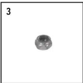
natural_image
Simple grayscale image of a spherical object with a label '3' in the top-left corner (no other text or symbols)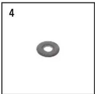
natural_image
Simple grayscale image of a ring-shaped object with no text or symbols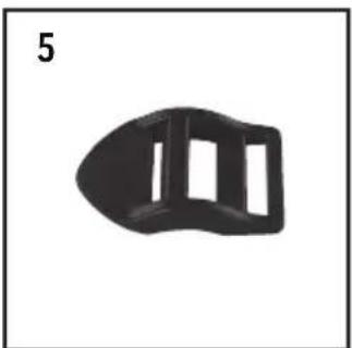
natural_image
Black plastic object with three rectangular cutouts, labeled '5' in top-left corner (no other text or symbols)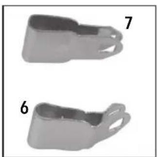
natural_image
Two grayscale plastic objects labeled 6 and 7, showing different angles and sizes (no text or symbols beyond labels)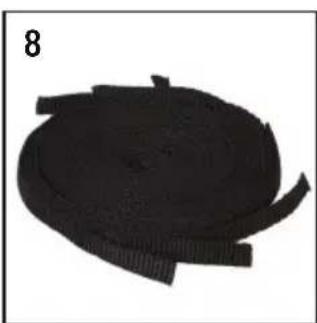
natural_image
Circular black object with segmented edges, possibly a mechanical or electronic component (no visible text or symbols)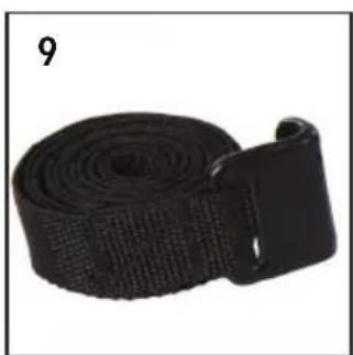
natural_image
Black rubber strap with textured band and handle, labeled with number 9 (no text or symbols on the strap itself)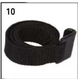
natural_image
Black textured strap with a loop detail, labeled '10' in the top-left corner (no other text or symbols)English ......04
Français ......10
Deutsch......16
Español......22
Italiano ......28
Nederlands ......34
Polski ......40
Introduction
Thank you for purchasing this Silverline product. This manual contains information necessary for safe and effective operation of this product. This product has unique features and, even if you are familiar with similar products, it is necessary to read this manual carefully to ensure you fully understand the instructions. Ensure all users of the product read and fully understand this manual.
Description of Symbols
The rating plate on your tool may show symbols. These represent important information about the product or instructions on its use.

Read instruction manual.

Maximum Load
Specification
Max load capacity....45kg
No. of bikes held 3
Max bike weight (total) 45kg
Mounting type ....Rear mounted
Dimensions (L x W x H) 750 x 515 x 95mm
Weight....2.5kg
As part of our ongoing product development, specifications of Silverline products may alter without notice.
General Safety
Carefully read and understand this manual and any label attached to the product before use. Keep these instructions with the product for future reference. Ensure all persons who use this product are fully acquainted with these instructions.
- Do not force, or attempt to use this product for a purpose for which it was not designed.
- The use of any attachment or accessory other than those mentioned in this manual could result in damage or injury.
r accessories could be dangerous, and may invalidate your warranty.
Bicycle Carrier Safety
WARNING: Always retighten vehicle mounting straps after cycles have been mounted on the carrier.
DO NOT exceed the maximum load for this product: 45kg for 3 adult sized cycles. If the carrier is used on a booted saloon type vehicle 30kg or 2 adult sized vehicles.
Check the tension of the straps at regular intervals whilst the carrier is fitted and tighten as necessary. Adjust the length between intervals depending on the road surface.
DO NOT obscure vehicle lighting or number plate with bicycles or carrier. If obstruction is unavoidable ALWAYS use a lighting/number plate board to comply with road traffic regulations.
Whilst using the carrier, the handling of the vehicle will be affected when carrying bicycles.
DO NOT operate the rear windscreen wiper whilst the carrier is fitted, as the carrier may obstruct the movement of the wiper and cause damage to the wiper mechanism or the carrier.
Ensure that the bicycles are positioned on the carrier so they are not overhanging the width of the vehicle, the exhaust pipe or in contact with the vehicle paintwork, and are sufficiently placed with enough ground clearance between the bicycles and the road.
When using the bicycle carrier in a country other than the UK, check with the relevant transport authorities as use in some countries is restricted
IMPORTANT: Take extra care whilst travelling over humps, ramps and rough/uneven road surfaces.
- Straps should be protected against friction, sharp edges or any surface likely to cause damage
- Never knot or twist a strap
- All straps should be inspected before use by a competent person
- Never attempt to repair straps. If in doubt withdraw from service and consult the retailer
- Avoid contact with heat and hot surfaces
-
Never trap a strap under a load; crushing can seriously damage straps
-
Checks should also include any fittings used in association with the strap
- Chemical exposure results in local weakening and softening of the material. This is indicated by flaking of the surface which may be plucked or rubbed off. If this is visible, the strap should be removed from service
- Heat or friction damage is indicated by the fibres taking on a glazed appearance; in extreme cases, fusion of the fibres can occur. If this is visible, the ratchet strap should be removed from service
Intended Use
Rear-mounted bicycle carrier rack, for use with most light vehicles for carrying up to 3 adult bicycles. This product is not recommended for the following type of vehicles:
- Sports cars
- Cabriolets
- Split tailgate
- Side opening tailgate
Unpacking Your Product
- Carefully unpack and inspect your new product. Familiarise yourself with all its features and functions
- Ensure that all parts of the product are present and in good condition. If any parts are missing or damaged, have such parts replaced before attempting to use this product
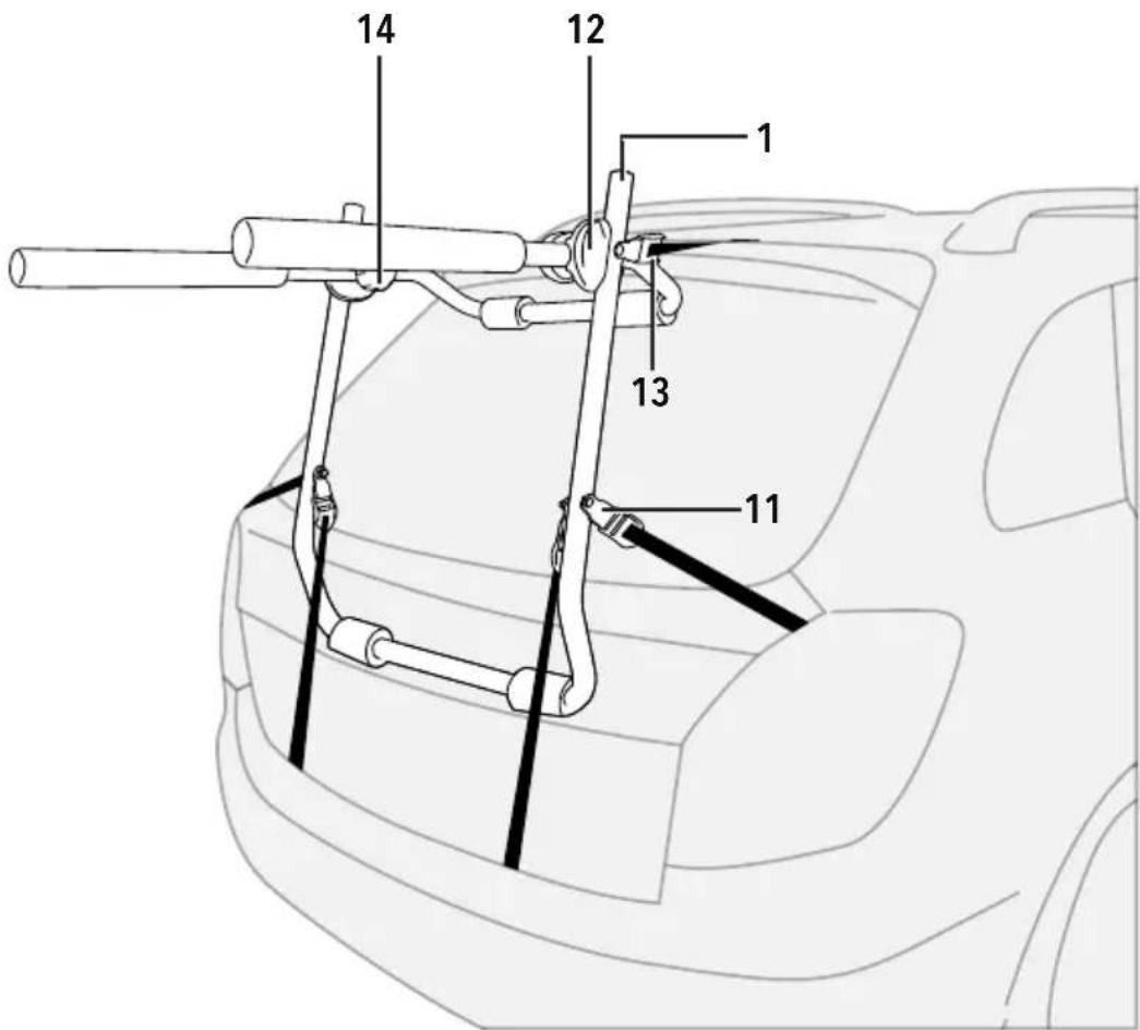
Product Familiarisation
- Bicycle Carrier Frame
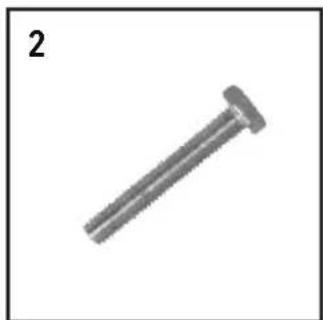
- N6 10 x 40mm Bolt
- M6 10mm Nylon Locking Nut
- M6 Washer
- Plastic Strap Buckle
- Angled Steel Anchor Loops
- Flat Steel Anchor Loops
- Bicycle Fastening Strap (700 x 10mm)
- Strap with Rubber-Coated Hooks (1200mm)
- Strap with Rubber-Coated Hooks (930mm)
- Plastic Strap Buckle Mounting Hole
- Locking Mechanism
- Metal Spring Locking Buckle
- Locking Mechanism Knob
Assembly
Fitting the lower and side strap anchor buckles
natural_image
Line drawing of two car wheel slots, one with ribbed design and the other with a handle (no text or symbols)- Clip one of the Plastic Strap Buckles (5) on to one of the Angled Steel Anchor Loops (6)
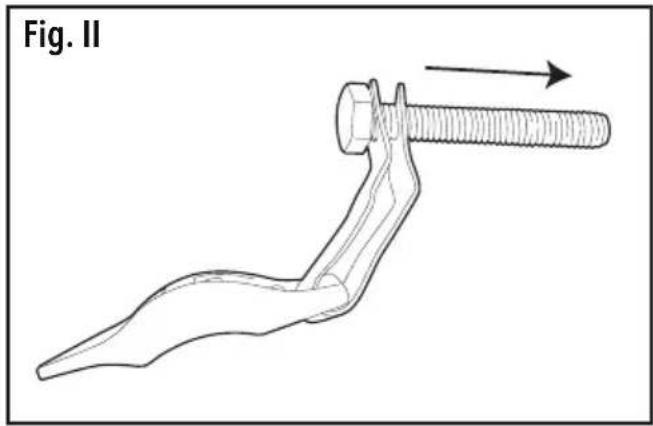
- Slide one of the M6 10 x 40mm Bolts (2) through the Angled Steel Anchor Loop (6)
natural_image
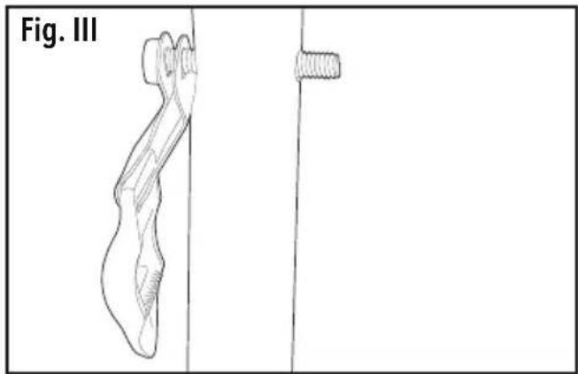
Line drawing of a human leg and foot with a small object on the right side (no text or symbols)- Push the Bolt with the Loop through the Buckle Mounting Hole (11) on the Frame (1)
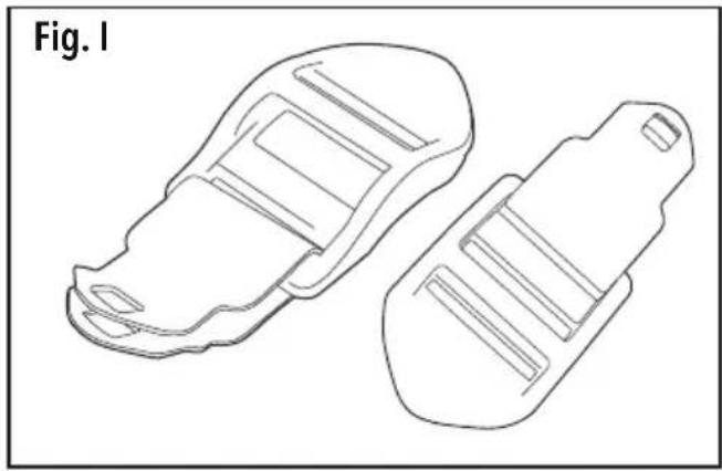
4 Clip one of the Plastic Strap Buckles on to one of the Flat Steel Anchor Loops (7) (Fig. 1)
- Next place the Flat Steel Anchor Loop (7) on the protruding Bolt followed by a Washer (4) and an M6 Nylon Locking Nut (3)
- Using two 10mm spanners (not supplied), tighten the nut, but do not overtighten to allow for adjustment
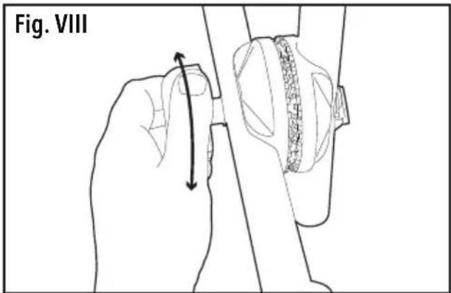
Attaching the Straps
• Feed the 1200mm Straps (9) through the Spring Lock Buckles (13)
• Feed the 930mm Straps (10) through the Plastic Buckles (5)
Operation
Adjusting the carrier angle
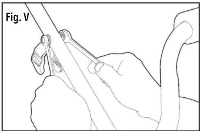
- Slacken the Locking Mechanism Knobs (14) by turning anti-clockwise to disengage the Toothed Angle Adjustment Cogs.
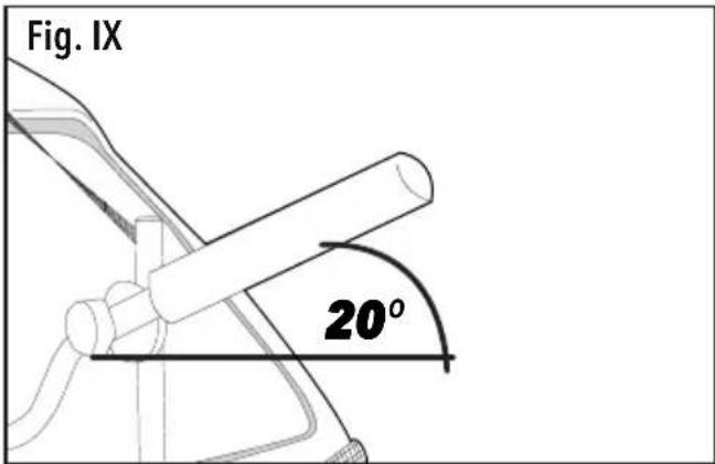
- Adjust the carrier so there is a minimum of a 20^ upward angle from the horizontal position away from the vehicle once in final position.
- Ensure the teeth on the Angle Adjustment Cogs align correctly and retighten the Knobs
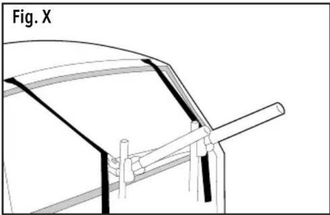
Fitting the carrier
natural_image
Technical line drawing of a car's front wheel assembly (no text or symbols)- Ensure the vehicle tailgate/bumper are clean before installation
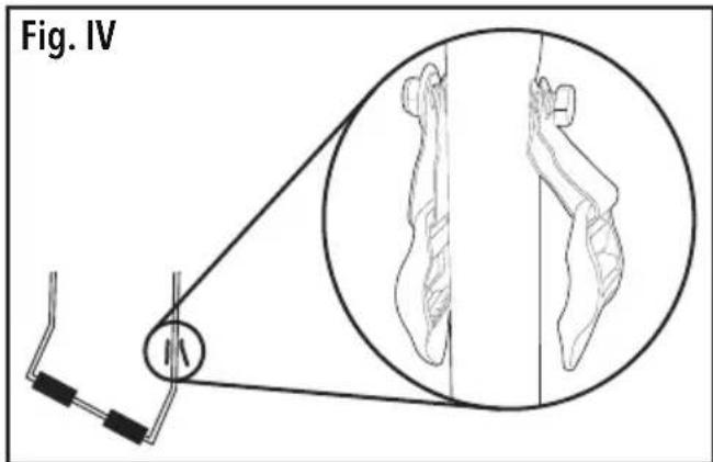
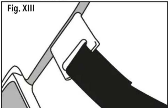
- Once the carrier is correctly assembled, open the tailgate and hook the upper straps over the top edge of the vehicle tailgate
- Close the tailgate and tighten the upper straps until the slack in the straps is taken up.
Note: if the panel gap isn't sufficient to accommodate the hooks, a dumbbell fitting or similar will be required to prevent damage to the vehicle or hooks.
IMPORTANT: Panel hooks should not be used to secure the carrier to glass edges or flexible panels.
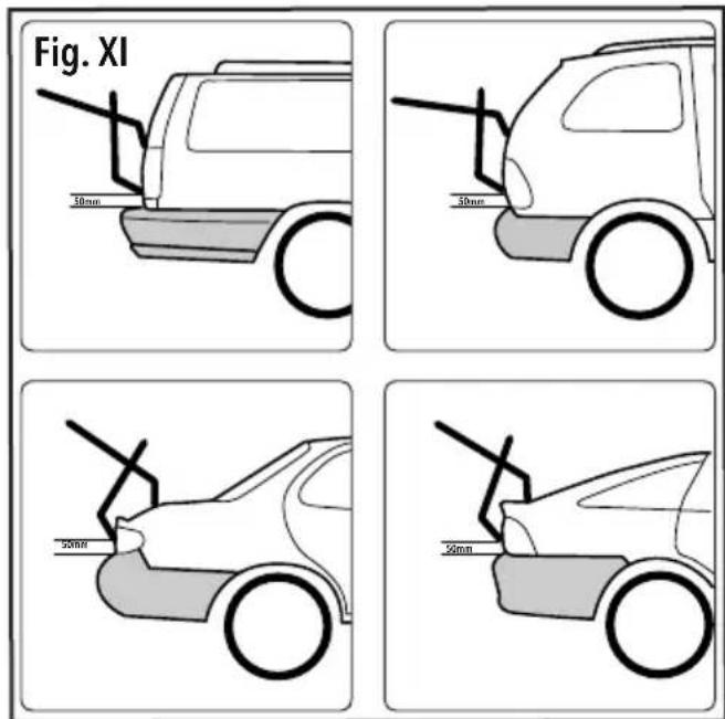
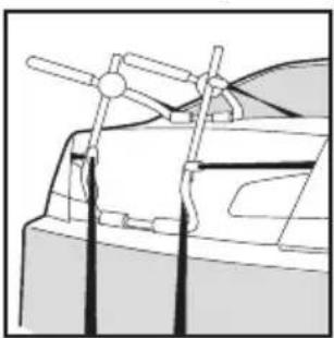
- Place the carrier against the vehicle approximately 50mm above the base of the tailgate
- Adjust the Carrier (see 'Adjusting the carrier angle'), so it sits against the tailgate of the vehicle, ensuring that the upper section rests in the upper or lower third of the panel on which it sits (not the middle).
- The Frame should be leaning towards the vehicle when in position whilst maintaining an approximate clearance of 100mm from the vehicle. This gap will reduce as the straps are tightened
natural_image
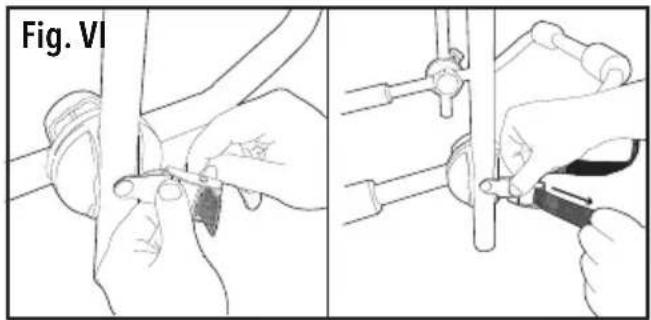
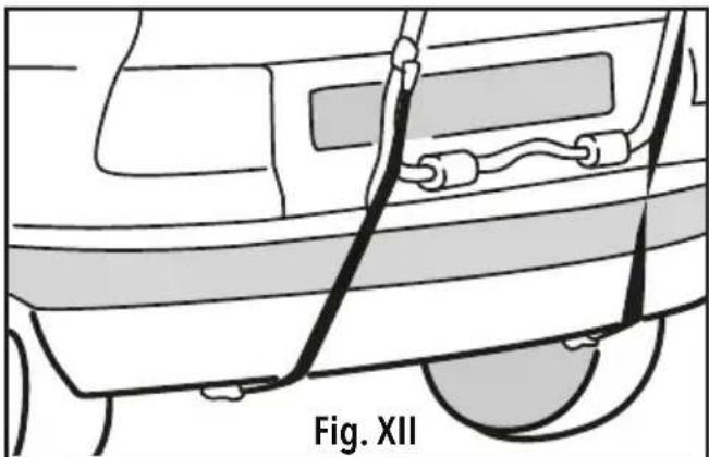
Line drawing of a car's front panel with cable and connectors, labeled Fig. XII (no text or symbols on the diagram itself)- Once correctly positioned, attach the bottom straps to a secure place at the rear of the vehicle - ideally the chassis or tailgate
WARNING: DO NOT attach the lower straps to the plastic bumper or other plastic parts as they are likely to distort or break under load.
natural_image
Technical diagram of a mechanical clamp or bracket assembly (no text or symbols)-
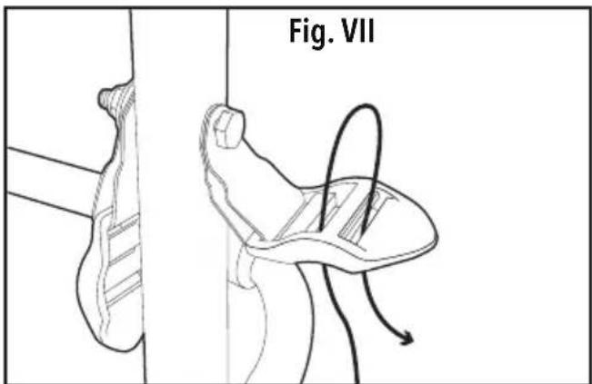
Attach the side hooks to the tailgate
-
Take up any slack from all straps
-
Progressively tighten each pair of straps in order: top/bottom/side
-
Repeat tightening process until the carrier is secure
Note: the clearance between the carrier and the bodywork and the carrier and the bumper will decrease during tightening. Ensure that, once secure, there is a minimum of 5cm between the carrier and the bodywork and that there is still clearance maintained above the bumper.
- Once the carrier is secured and checked, the bicycles can be mounted and secured to the carrier using the straps provided or an alternative fixing method (not supplied)
- Ensure all moving parts of the bicycles are secured in a stationary position.
- The bicycles MUST be fixed to the carrier via the frame and mounted on the foam padded bars ONLY, to prevent damage to the bicycles, carrier or vehicle.
- IMPORTANT: Ensure ALL bicycles are securely fitted to the carrier before travelling.
natural_image
Technical line drawing of a mechanical assembly with no visible text or symbols
natural_image
Technical line drawing of a car's front suspension system with hoses and brackets (no text or symbols)Maintenance
General inspection
Regularly check that all the fixing screws are tight.
Keep the carrier clean. Dirt and dust will cause parts to wear quickly and shorten the carriers service life
Clean the carrier with a soft damp cloth using warm water. Do not use alcohol, petrol or strong cleaning agents
Never use caustic agents to clean plastic parts
Lubrication
Slightly lubricate all moving parts at regular intervals with a suitable spray lubricant
Contact
For technical or repair service advice, please contact the helpline on (+44) 1935 382 222
Web: silverlinetools.com/en-GB/Support
Address:
Powerbox
Boundary Way
Lufton Trading Estate
Yeovil, Somerset
BA22 8HZ, United Kingdom
Storage
Store this tool carefully in a secure, dry place out of the reach of children
Silverline Tools Guarantee
This Silverline product comes with a 3 year guarantee
Register this product at www.silverlinetools.com within 30 days of purchase in order to qualify for the 3 year guarantee. Guarantee period begins according to the date of purchase on your sales receipt.
Registering your purchase
Registration is made at silverlinetools.com by selecting the Guarantee Registration button. You will need to enter:-
- Your personal details
• Details of the product and purchase information
Once this information is entered your guarantee certificate will be created in PDF format for you to print out and keep with your purchase.
Terms & Conditions
Guarantee period becomes effective from the date of retail purchase as detailed on your sales receipt.
PLEASE KEEP YOUR SALES RECEIPT
If this product develops a fault within 30 days of purchase, return it to the stockist where it was purchased, with your receipt, stating details of the fault. You will receive a replacement or refund.
If this product develops a fault after the 30 day period, return it to:
Silverline Tools Service Centre
PO Box 2988
Yeovil
BA21 1WU, UK
The guarantee claim must be submitted during the guarantee period.
You must provide the original sales receipt indicating the purchase date, your name, address and place of purchase before any work can be carried out.
You must provide precise details of the fault requiring correction.
Claims made within the guarantee period will be verified by Silverline Tools to establish if the deficiencies are related to material or manufacturing of the product.
Carriage will not be refunded. Items for return must be in a suitably clean and safe state for repair, and should be packaged carefully to prevent damage or injury during transportation. We may reject unsuitable or unsafe deliveries.
All work will be carried out by Silverline Tools or its authorized repair agents.
The repair or replacement of the product will not extend the period of guarantee
Defects recognised by us as being covered by the guarantee shall be corrected by means of repair of the tool, free of charge (excluding carriage charges) or by replacement with a tool in perfect working order.
Retained tools, or parts, for which a replacement has been issued, will become the property of Silverline Tools.
The repair or replacement of your product under guarantee provides benefits which are additional to and do not affect your statutory rights as a consumer.
What is covered:
The repair of the product, if it can be verified to the satisfaction of Silverline Tools that the deficiencies were due to faulty materials or workmanship within the guarantee period.
If any part is no longer available or out of manufacture, Silverline Tools will replace it with a functional replacement part.
Use of this product in the EU.
What is not covered:
Silverline Tools does not guarantee repairs required as a result of:
Normal wear and tear caused by use in accordance with the operating instructions eg blades, brushes, belts, bulbs, batteries etc.
The replacement of any provided accessories drill bits, blades, sanding sheets, cutting discs and other related items.
Accidental damage, faults caused by negligent use or care, misuse, neglect, careless operation or handling of the product.
Use of the product for anything other than normal domestic purposes.
Change or modification of the product in any way.
Use of parts and accessories which are not genuine Silverline Tools components.
Faulty installation (except installed by Silverline Tools).
Repairs or alterations carried out by parties other than Silverline Tools or its authorized repair agents.
Claims other than the right to correction of faults on the tool named in these guarantee conditions are not covered by the guarantee.
Introduction
natural_image
Line drawing of two car wheel slots, one with ribbed design and the other with a handle (no text or symbols)natural_image
Line drawing of a mechanical component with a separate cylindrical part, labeled Fig. III (no text or symbols on the diagram itself)natural_image
Technical line drawing of a mechanical component with no visible text or symbolsnatural_image
Diagram of a car's front panel with cable and connectors, labeled Fig. XII (no text or symbols on diagram itself)natural_image
Technical diagram of a mechanical component labeled Fig. XIII, showing a clamping mechanism (no text or symbols on the diagram itself)natural_image
Line drawing of a car front view with visible structural components (no text or symbols)
natural_image
Technical line drawing of a mechanical assembly with no visible text or symbolsEntretien
Inspection générale
natural_image
Line drawing of two mechanical components with ribbed surfaces (no text or symbols)natural_image
Line drawing of a human figure with a vertical line and a horizontal line, labeled 'Abb. III' (no text or symbols on the figure itself)natural_image
Technical line drawing of a vehicle's roof structure with no visible text or symbolsnatural_image
Technical line drawing of a car front view with visible structural components (no text or symbols)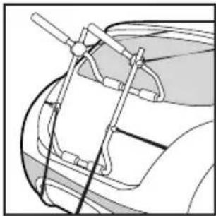
natural_image
Technical line drawing of a car's front suspension system with hoses and brackets (no text or symbols)Wartung und Pflege
Silverline Tools Service Centre
PO Box 2988
Yeovil
natural_image
Line drawing of two car wheel slots, one with ribbed design and the other with a handle (no text or symbols)natural_image
Line drawing of a human leg and foot with a separate separate object, labeled 'Fig. III' (no text or symbols on the diagram itself)natural_image
Line drawing of a hand holding a tool, labeled 'Fig. V' (no other text or symbols)natural_image
Technical line drawing of a mechanical component with no visible text or symbolsnatural_image
Line drawing of a car's front panel with cable and connectors, labeled Fig. XII (no text or symbols on the diagram itself)natural_image
Technical diagram of a mechanical component labeled Fig. XIII, showing a clamping mechanism with no visible text or symbols.natural_image
Technical line drawing of a mechanical clamp or bracket assembly mounted on a vehicle (no text or symbols visible)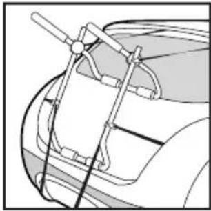
natural_image
Technical line drawing of a mechanical assembly with no visible text or symbolsnatural_image
Line drawing of two car wheel slots, one with ribbed design and the other with a handle (no text or symbols)natural_image
Line drawing of a mechanical component with two views: one showing a bent part and the other a threaded end, labeled 'Fig. III' (no text or symbols on the diagram itself)natural_image
Technical line drawing of a mechanical component with no visible text or symbolsnatural_image
Line drawing of a car's front bumper with attached cable and connectors, labeled Fig. XII (no text or symbols on the diagram itself)natural_image
Technical diagram of a mechanical component labeled Fig. XIII, showing a clamping mechanism (no text or symbols on the diagram itself)natural_image
Line drawing of a vehicle's front suspension system with lever arms and structural components (no text or symbols)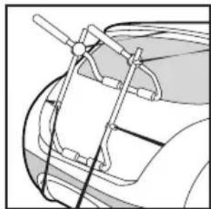
natural_image
Technical line drawing of a mechanical assembly with no visible text or symbolsManutenzione
Ispezione generale
Silverline Tools Service Centre
PO Box 2988
Yeovil
BA21 1WU, GB
natural_image
Line drawing of two car wheel slots, one with ribbed design and the other with a handle (no text or symbols)natural_image
Line drawing of a human leg and foot with a separate inset showing a textured object (no text or symbols)natural_image
Technical line drawing of a mechanical component with no visible text or symbolsnatural_image
Diagram of a car's front panel showing cable routing and labeled section (Fig. XII), no text or symbols beyond label.natural_image
Technical diagram of a mechanical component labeled Fig. XIII, showing a clamping mechanism (no text or symbols on the diagram itself)natural_image
Diagram of a car's front suspension system with lift and lock components (no text or labels)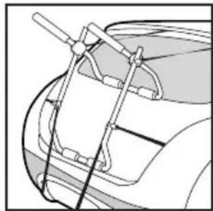
natural_image
Technical line drawing of a car's front suspension system with hoses and brackets (no text or symbols)Algemene inspectie
Silverline Tools Service Centre
PO Box 2988
Yeovil
BA21 1WU, GB
natural_image
Line drawing of two car wheel rim components (no text or symbols)natural_image
Technical line drawing of a mechanical assembly with no visible text or symbols
natural_image
Technical line drawing of a car's front suspension system with hoses and brackets (no text or symbols)Kontrola rutynowa
Silverline Tools Service Centre
PO Box 2988
Yeovil
BA21 1WU, UK
natural_image
Mechanical linkage component with black rods and connectors (no text or symbols visible)GB 3 Year Guarantee. Register online within 30 days. Terms and Conditions apply.