VTTEST11N - Multimeter VELLEMAN - Free user manual and instructions
Find the device manual for free VTTEST11N VELLEMAN in PDF.

Questions des utilisateurs sur VTTEST11N VELLEMAN
0 question sur cet appareil. Repondez a celles que vous connaissez ou posez la votre.
Poser une nouvelle question sur cet appareil
Download the instructions for your Multimeter in PDF format for free! Find your manual VTTEST11N - VELLEMAN and take your electronic device back in hand. On this page are published all the documents necessary for the use of your device. VTTEST11N by VELLEMAN.
USER MANUAL VTTEST11N VELLEMAN
Thank you for before brin
symbol on the device
sal of the device afte
alized company for r
r distributor or to a l
this device into ser
stall or use it and co
s, burns, and even d
case, the cable trac
t use the device in a
device from shocks a
r its lifecycle could h
se of the unit (or bat
it should be taken t
ice. If the device was
tact your dealer. ntify and trace wires
d to test continuity al
trical circuits can ca
ath if the circuit is to
tracker is used for t
nd abuse. Avoid brut
h off both the trans
ourself with the func
ions of the device ar
sed by user modifica
device for its intend
connect the test lea
hort circuit between
itter and the receive tions of the device b
forbidden for safety
tions to the device is ed purpose. Usin
d the dealer will not
6 test leads 7 phone connec
he wires to be tested
hts up, the two teste
reasons. not covered
r DC- not a cable at the far
o If the CONT indicator [8] does not light, one or both of the wires are broken, or the wrong wires were connected or short circuited. Caution: Make sure the pair of wires under test is not in contact with any other electrified or earthed object, as this may cause an incorrect result.
4.2 Cable Detection / Test
Use both the tone generator and the cable tracker to verify where a cable is going, if it is interrupted or not and where the interruption is located.
1. Set the tone generator's mode switch [9] to TONE.
The TONE indicator [8] starts flashing.
2. At one end of the cable / wires to be tested, connect the red clip
to any wire or one specific wire you want to test. Connect the black clip to the ground wire or, if you cannot find it, one of the other wires.
3. Use the volume control [2] on the side of the cable tracker to
4. Use the probe tip [1] of the cable tracker as follows:
o If you do not know where the cable is going or if there are several similar cables, you can detect the correct one with the probe. Hold the probe to the suspected wire and press the trace button. The signal is the loudest at the correct wire. o If you do know where the cable is going, the probe allows you to verify immediately at the other end whether or not the cable is interrupted. Hold the probe to the end of the wire and press the trace button. If no signal is obtained, the test wire is probably interrupted. o Press and hold the trace button [3] and follow the cable to where the signal stops: the signal wire is interrupted at that point. Remarks:
- The best test results are obtained when the black clip is connected to a separate ground wire.
- The probe is very sensitive: as it gets nearer the signal wire, the tone gets louder.
- Electric fields may interfere with the detection of the signal wire.VTTEST11N
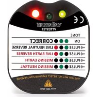
The tone generator can be used to determine the polarity of a phone line, and the status of a working line.
1. Set the tone generator's mode switch [9] to OFF.
2. Insert the phone line connector [7] in the phone socket and
connect the red and black connectors [6] to the wires to be connected. The CONT indicator [8] lights. o Green means the polarity is correct (black is "+" (tip) and red is "–" (ring)). o Red means the polarity is inversed (black is "–" (ring) and red is "+" (tip)). o If the LED does not light up, either the connections are not established correctly or the socket is not connected.
3. To test the status of a telephone line, first connect the red
connector to the "–" (ring) side and the black connector to the "+" (tip) side. The CONT indicator [8] lights. o Green indicates a clear line. o Flickering yellow means there is an incoming phone call (ring signal). Note: In this case, set the mode switch to CONT to terminate the call on the line. o If the LED does not light up, the line is busy.
4.4 Selecting the Tone
Select the tone you want to hear (single or dual tone) with the audio signal switch at the inside of the tone generator.
1. Open the battery compartment and remove the battery.
2. Unscrew the screw in the battery compartment and the four
screws in the back cover.
3. Carefully remove the back cover and lift the PCB.
The audio signal switch is located at the left side of the PCB (component side up, battery connectors at the bottom).
4. Set the switch in the desired position.
5. Replace the PCB carefully and put the cover back.
Caution: Make sure that no wires are crimped and that the mode switch is in position. The indicator LEDs should fit easily through the holes. Do not force.
6. Fix the back cover with the 5 screws.
maximum dimensions receiver transmit
e. Do not attempt to
the battery cover at
battery cover and ti
batteries from the d
vice in a dry and du
e form squa o frequency ± 1
r throw them in fire
of batteries in acco
eries away from chil
he battery cover at t
t-free place at room
sed for a the device.
prior notice. © COPYRIGH
nslated or reduced t
out the prior written
this device. oduct and the late
rt of this manual ma
onsent of the copyri
r defecten of proble
SA Velleman notice. Tous
- All consumer products are subject to a 24- month warranty on production flaws and defective material as from the original date of purchase.
- Velleman® can decide to replace an article with an equivalent article, or to refund the retail value totally or partially when the complaint is valid and a free repair or replacement of the article is impossible, or if the expenses are out of proportion. You will be delivered a replacing article or a refund at the value of 100% of the purchase price in case of a flaw occurred in the first year after the date of purchase and delivery, or a replacing article at 50% of the purchase price or a refund at the value of 50% of the retail value in case of a flaw occurred in the second year after the date of purchase and delivery.
- Not covered by warranty: - all direct or indirect damage caused after delivery to the article (e.g. by oxidation, shocks, falls, dust, dirt, humidity...), and by the article, as well as its contents (e.g. data loss), compensation for loss of profits; - consumable goods, parts or accessories that are subject to an aging process during normal use, such as batteries (rechargeable, non-rechargeable, built-in or replaceable), lamps, rubber parts, drive belts... (unlimited list); - flaws resulting from fire, water damage, lightning, accident, natural disaster, etc.…; - flaws caused deliberately, negligently or resulting from improper handling, negligent maintenance, abusive use or use contrary to the manufacturer’s instructions; - damage caused by a commercial, professional or collective use of the article (the warranty validity will be reduced to six (6) months when the article is used professionally); - damage resulting from an inappropriate packing and shipping of the article; - all damage caused by modification, repair or alteration performed by a third party without written permission by Velleman®.
- Articles to be repaired must be delivered to your Velleman® dealer, solidly packed (preferably in the original packaging), and be completed with the original receipt of purchase and a clear flaw description.
- Hint: In order to save on cost and time, please reread the manual and check if the flaw is caused by obvious causes prior to presenting the article for repair. Note that returning a non-defective article can also involve handling costs.
- Repairs occurring after warranty expiration are subject to shipping costs.
- The above conditions are without prejudice to all commercial warranties. The above enumeration is subject to modification according to the article (see article’s manual).