
CFB 9433 XH - Range hood BEKO - Free user manual and instructions
Find the device manual for free CFB 9433 XH BEKO in PDF.
| Product type | Extractor hood |
| Brand | Beko |
| Model | CFB 9433 XH |
| Supply voltage | 220-240 V ~ 50 Hz |
| Motor power | 2 x 115 W |
| Lighting power | 2 x 4 W (LED) |
| Maximum airflow | 380 m³/h (3 speeds) |
| Number of speeds | 3 |
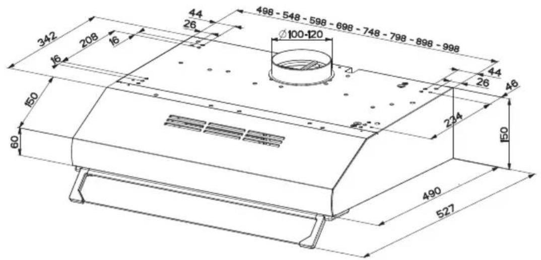
| Connection diameter | 120 or 150 mm |
| Minimum installation height | 65 cm |
| Grease filter | Washable aluminium (monthly cleaning) |
| Charcoal filter | Active, replaceable every 3 months (recirculation) |
| Operating mode | Extraction or recirculation |
| Insulation class | Class II |
| Energy efficiency class (lighting) | F |
| Material | Stainless steel |
| Use | Domestic |
| Spare parts available | For 12 years after purchase |
| Compliance | WEEE, RoHS |
Frequently Asked Questions - CFB 9433 XH BEKO
User questions about CFB 9433 XH BEKO
0 question about this device. Answer the ones you know or ask your own.
Ask a new question about this device
Download the instructions for your Range hood in PDF format for free! Find your manual CFB 9433 XH - BEKO and take your electronic device back in hand. On this page are published all the documents necessary for the use of your device. CFB 9433 XH by BEKO.
USER MANUAL CFB 9433 XH BEKO
natural_image
Simple line drawing of a chimney emitting steam (no text or symbols)CFB 9433 XH
EN - FR - DE - NL - PT - LT - SK - HR - EL - TR - BG - RU - TH - VI - SL - ZH - MS
CONTENTS
| ENGLISH | 3-13 |
| FRANÇAIS | 14-26 |
| DEUTSCH | 27-40 |
| NEDERLANDS | 41-51 |
| PORTUGUÊS | 52-64 |
| LIETUVIŲ K 65-75 | |
| SLOVENSKÝ | 76-86 |
| HRVATSKI | 87-97 |
| ΕΛΛΗΝΙΚΑ 98-112 | |
| TÜRKÇE 113-127 | |
| ΒЪЛГАРСКИ 128-142 | |
| РУССКИЙ 143-161 | |
| ไทย 162-175 | |
| TIÉNG VIỆT 176-188 | |
| SLOVENŠČINA | 189-199 |
| 中国 200-209 | |
| MALAY | 210-221 |
Please read this user manual first!
Dear Valued Customer,
Thank you for preferring this Beko appliance. We hope that you get the best results from your appliance which has been manufactured with high quality and state-of-the-art technology. For this reason, please read this entire user manual and all other accompanying documents carefully before using the appliance and keep it as a reference for future use. If you handover the appliance to someone else, give the user manual as well. Follow the instructions by paying attention to all the information and warnings in the user manual.
Remember that this user manual may also apply to other models. Differences between models are explicitly described in the manual.
Meanings of the Symbols
Following symbols are used in various sections of this user manual:

Important information and useful hints about usage.

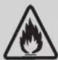
WARNING: Warnings against dangerous situations concerning the security of life and property.
WARNING: Warning for danger of fire.
WARNING: Warning for electric shock.

Protection class for electric shock.
1 Important safety and environmental instructions
1.1 General Safety
Important Safety Instructions Read Carefully And Keep For Future Reference This section contains safety instructions that will help protect from risk of fire, electric shock, exposure to leak microwave energy, personal injury or property damage. Failure to follow these instructions shall void any warranty.
- Beko products comply with the applicable safety standards; therefore, in case of any damage on the appliance or power cable, it should be repaired or replaced by the dealer, service center or a specialist and authorized service alike to avoid any danger. Faulty or unqualified repair work may be dangerous and cause risk to the user.
- This appliance is intended to be used in household and similar applications such as:
- Staff kitchen areas in shops, offices and other working environments;
- Farm houses
- By clients in hotels, and other residential type environments;
— Bed and Breakfast type environments.
- Operate the appliance for its intended purpose only as described in this manual.
- The manufacturer cannot be held liable for damages resulting from improper installation or misuse of the product.
- This appliance can be used by children aged from 8 years and above and persons with reduced physical, sensory or mental capabilities or lack of experience and knowledge if they have been given supervision or instruction concerning use of the appliance in a safe way and understand the hazards involved.
• Children shall not be allowed play with the appliance. Cleaning and user maintenance shall not be made by children without supervision.
- The minimum distance between the supporting surface for the
1 Important safety and environmental instructions
cooking vessels on the hob and the lowest part of your product must be at least 65 cm.
- If the instructions for installation for the gas hob specify a greater distance, this has to be taken into account.
- Make sure that your mains power supply complies with the information supplied on the rating plate of the appliance.
- Never use the appliance if the power cable or the appliance itself is damaged.
- Prevent damage to the power cable by not squeezing, bending, or rubbing it on sharp edges. Keep the power cable away from hot surfaces and naked flame.
- Use the appliance with a grounded outlet only.
WARNING: Do not connect the appliance to the mains until the installation is fully complete.
- Place the appliance in a way so that the plug is always accessible.
- Do not touch the lamps if they have operated for a long time.
They can burn your hands since they will be hot.
- Follow the regulations set out by competent authorities on discharge of the exhaust air (this warning is not applicable for use without flue).
- Operate your appliance after putting a pot, pan etc. on the hob. Otherwise, high heat may cause deformation in some parts of your product.
- Turn off the hob before taking the pot, pan etc. from it.
- Do not leave hot on the hob. Pans with hot may cause self combustion.
- Pay attention to your curtains and covers since may catch fire while cooking food such as fries.
- Grease filter must be cleaned at least monthly. Carbon filter must be replaced at least every 3 months.
- Product shall be cleaned accordance with user manual. If cleaning was not carried out in accordance with user manual, there may be fire risk.
1 Important safety and environmental instructions
- Do not use non-fire-resistant filtering materials instead of the current filter.
- Only use the original parts or parts recommended by the manufacturer.
- Do not operate the product without the filter and do not remove the filters while the product is running.
- In the event of be started any flame, de-energize your product and cooking appliances.
- In the event of be started any flame, cover the flame and never use water to extinguish.
- Unplug the appliance before each cleaning and when the appliance is not in use.
- The negative pressure in the environment should not exceed 4 Pa (4x10 bar) while the hood for electric hob and appliances running on another type of energy but electricity operate simultaneously.
- In the environment where the appliance is being used, the exhaust of devices running on fuel or gas, such as room heater must be absolutely isolated or
device must be hermetical type.
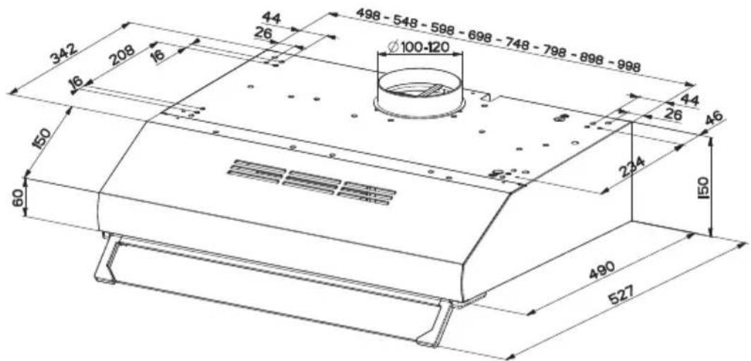
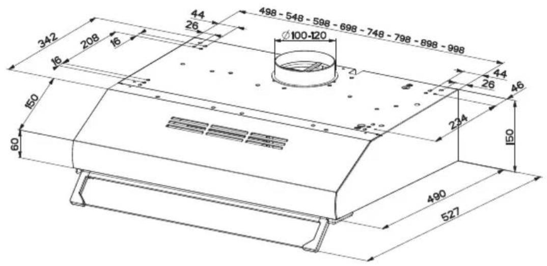
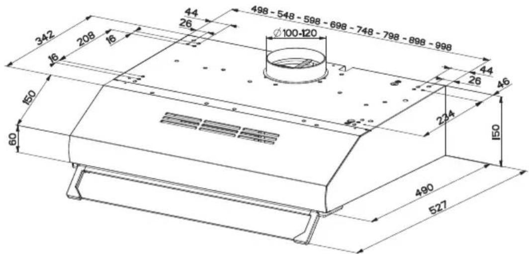
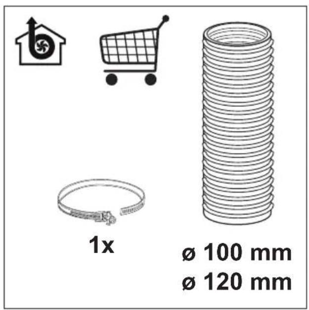
- When connecting the flue, use pipes with a diameter of 120 or 150 mm . Pipe connection must be as short as possible and have as few elbows as possible.
- Danger of choking! Keep all the packaging materials away from children.
CAUTION: Accessible parts may become hot when used with coo-king appliances.
- The product outlet must not be connected to air channels that include other smoke.
- The ventilation in the room may be insufficient when the hood for electric hob is used simultaneously with the devices operating on gas or other fuels (this may not apply to appliances that only discharge the air back into the room).
- Objects placed on the product may fall. Do not place any objects on the product.
- Do not flambe under the your product.
1 Important safety and environmental instructions
WARNING: Before installing the Hood, remove the protective films.
- Never leave high naked flames under the hood when it is in operation
- Deep fat fryers must be continuously monitored during use: overheated can burst into flames.
1.2 Compliance with the WEEE Directive and Disposing of the Waste Product:
This product complies with EU WEEE Directive (2012/19/EU). This product bears a classification symbol for waste electrical and electronic equipment (WEEE).
This symbol indicates that this product shall not be disposed with other household wastes at the end of its service life. Used device must be returned to official collection point for recycling of electrical and electronic devices. To find these collection systems please contact to your local authorities or retailer where the product was purchased. Each household performs important role in recovering and recycling of old appliance. Appropriate disposal of used appliance helps prevent potential negative consequences for the environment and human health.
1.3 Compliance with RoHS Directive
The product you have purchased complies with EU RoHS Directive (2011/65/EU). It does not contain harmful and prohibited materials specified in the Directive.
1.4 Package Information

Packaging materials of the product are manufactured from recyclable materials in accordance with our National Environment Regulations. Do not dispose of the packaging materials together with the domestic or other wastes. Take them to the packaging material collection points designated by the local authorities.
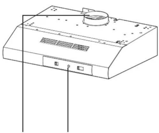
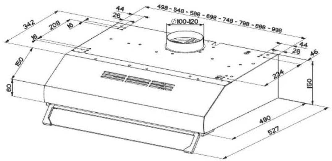
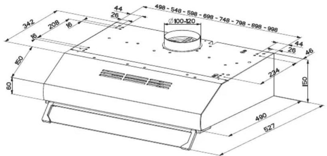
2 General appearance
2.1 Overview
natural_image
Line drawing of a front-end air purifier with ventilation slots and a circular top (no text or symbols)
natural_image
Technical line drawing of an open air duct system with internal components (no text or symbols)12345

- Body
- Grease filter
- Lighting
- Control panel
- Chimney
2.2 Technical data
| Model CFB 9433 XH | |
| Supply voltage & frequency | 220-240V ~ 50 Hz |
| Lamp power 2 x 4 W | |
| Motor power 2 x 115 W | |
| Air flow – 3. Level 380 m3/h | |
| Motor Insulation Class Class F | |
| Insulation class Class II |
3 Using the appliance
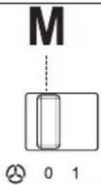
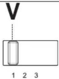
3.1 Controls panel
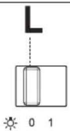

| L : Light on/off Switches the lighting system on and off. | |
| M : Motor on/off Switches the extractor motor on and off | |
| V : Speed button Sets the operating speed of the extractor:1. Low speed, used for a continuous and silent air change in the presence of light cooking vapour.2. Medium speed, suitable for most operating conditions given the optimum treated air flow/ noise level ratio.3. Maximum speed, used for eliminating the highest cooking vapour emission, including long periods. |
- The extractor hood has been designed exclusively for domestic use to eliminate kitchen smells.
- Never use the hood for purposes other than for which it has been designed.
- Never leave high naked flames under the hood when it is in operation.
- Adjust the flame intensity to direct it onto the bottom of the pan only, making sure that it does not engulf the sides.
- Deep fat fryers must be continuously monitored during use: overheated can burst into flames.
3.2 Efficient use in terms of energy saving
- When using your appliance, adjust the speed settings according to vapour and odour intensity, in order to save energy.
- Use low speeds (1-2) under normal conditions, and high speed (3) and boost mode for intense odour and vapour.
- The hood is equipped with lamps in order to illuminate the cooking area.
- Using them for environmental lighting shall cause unnecessary energy expenditure and insufficient lighting.
- For your device to consume less energy, run it at a low speed level.
- Your device will reduce energy consumption as it will run more efficiently when you provide sufficient air intake to it.
- Set your device to the intense suction power level before the formation of steam, in cases where you know that the dense steam will occur. So, you reduce energy consumption by using your device for a shorter time as it will have a sufficient air intake.
- Keep the lids of the cookware closed to reduce the steam evolving.
3 Using the appliance
3.3 Operating the Hood
- Hood is equipped with a motor having various speed settings.
- For a better performance, we advise you to use low speeds in normal conditions, and high speeds when smell and vapors are intensified.
- You can start the hood by pressing the desired speed level key.(V1,V2,V3)
- You can illuminate the cooking area by pressing the light key (L)
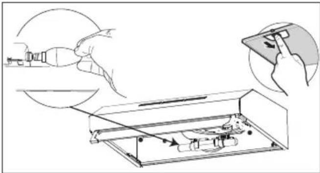
3.4 Lamp replacement

- Before replacing the light bulbs, disconnect the power supply of the hood.
- Do not touch the light bulbs when they are hot.
- Be careful not to touch the replaced light bulb directly with hands.

You may procure lamps from Authorised Service Agents.
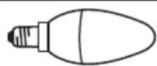
| Lamp | 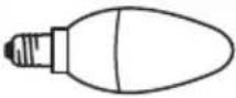 |
| Bulb power 4 W | |
| Holder/Socket E14 | |
| Bulb voltage 220 - 240 V |
| ILCOS Code D R B B / F | 4 - 2 2 0 - 240-E14-35/100 |
| Size 35x100 mm | |
| Luminous flux 400 lm | |
| Correlated colour temperature | 3000 K |
This product contains a light source of energy efficiency class "F".
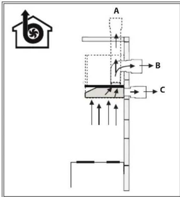
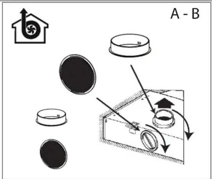
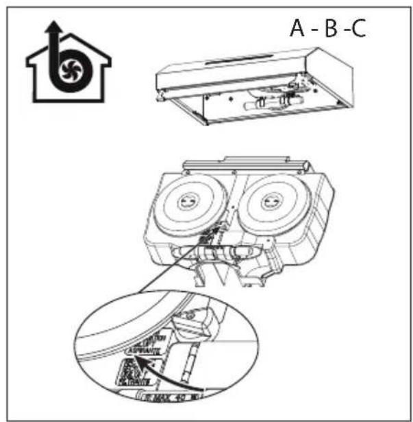
3.5 Operation with flue connection
- Vapour is extracted through the flue duct, which is fastened to the connection head on the hood.
- The diameter of the flue duct must be the same as the connection ring. In horizontal settings, the pipe has to have a slight upward slope (around 10irc ) so that the air can exit the room easily.
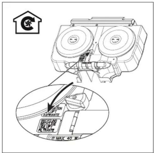
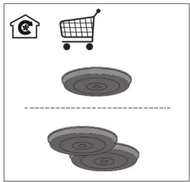
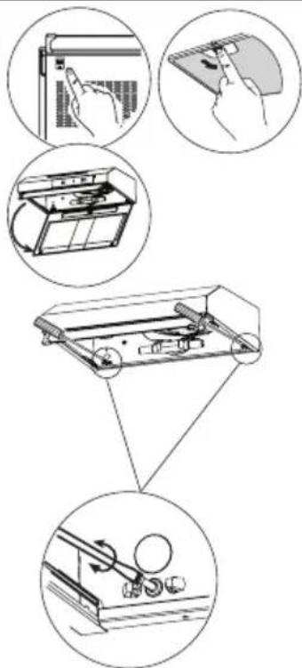
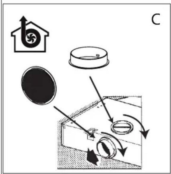
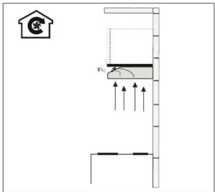
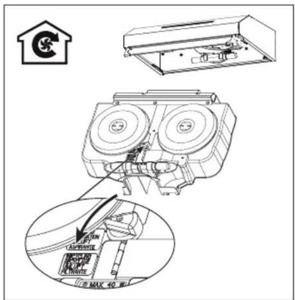
3.6 Operation without flue connection
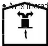
through the carbon filter and recirculated in the room. Carbon filter is used when it is impossible to use a flue in the house.
- In flueless use, remove the flaps inside the flue adapter.
- Remove the oil filter. To install the carbon filter, fit the filter to the tabs by centring it on the plastic piece on both sides of the fan body. Tighten it by turning right or left.
- Replace aluminium oil filter.
4 Cleaning and maintenance
The device should be cleaned and maintained regularly. Failure to keep the device clean will adversely affect the service life of the device. For cleaning and maintenance, follow the instructions stated in the manual.

Before cleaning and maintenance, unplug the product or turn off the switch.
Non-compliance with the provisions associated with the cleaning of the device and replacement of the filters may result in a risk of fire. Therefore, it is recommended to follow the guidelines stated here. The manufacturer is not responsible for the engine damages or fires originating from the improper use.
Clean using only a cloth dampened with a neutral liquid detergent. Do not use abrasive products or alcohol.
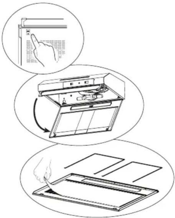
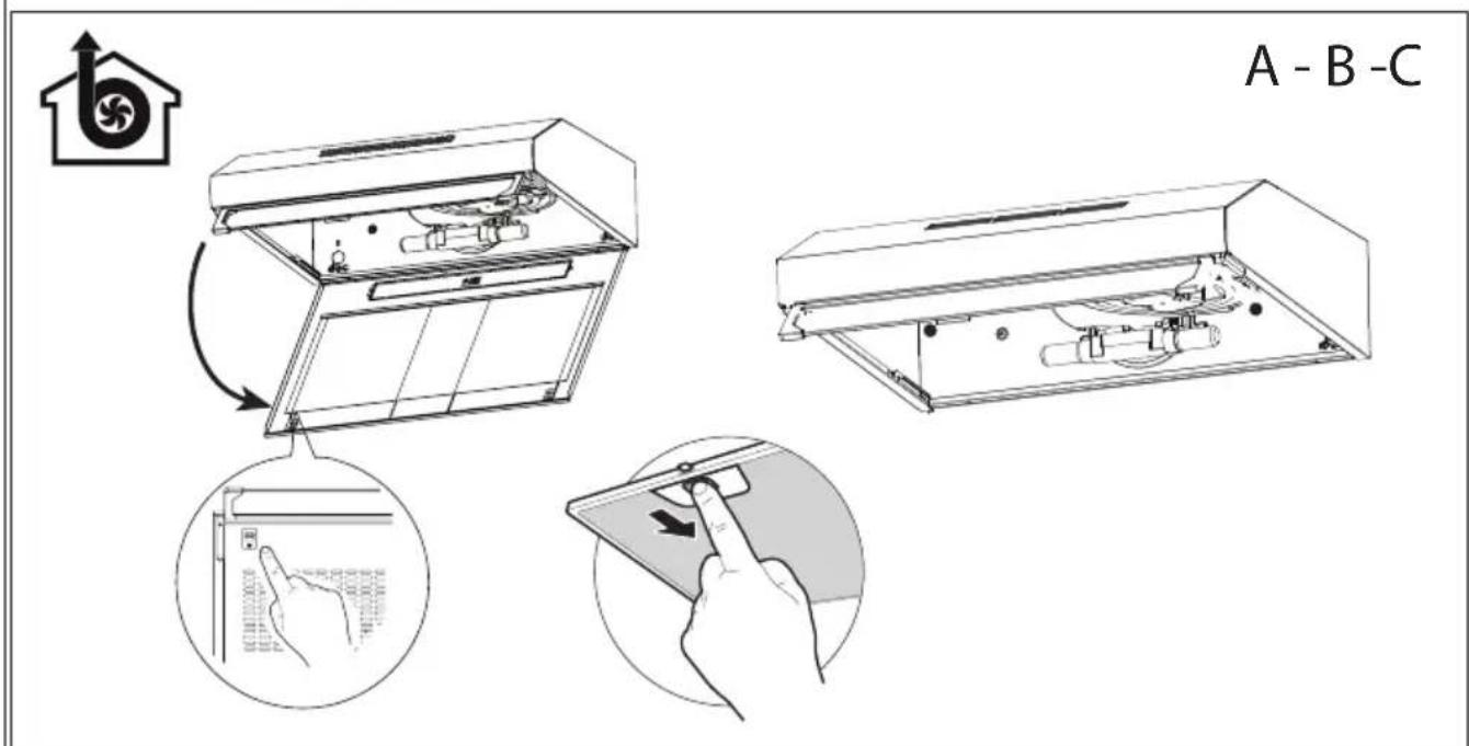
4.1 Cleaning of grease filter
This filter captures particles in the air. You are recommended to clean your filter every month under normal usage conditions. First remove the grease filters for this process. Wash the filters with liquid detergent and rinse them with water and install them back after they get dry. Grease filters may get discolored as they are washed; this is normal and you don't need to change your filter.

You can wash the grease filter in the dishwasher

CAUTION: In case of normal use, clean your filter once in a month.
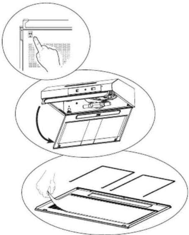
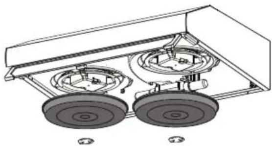
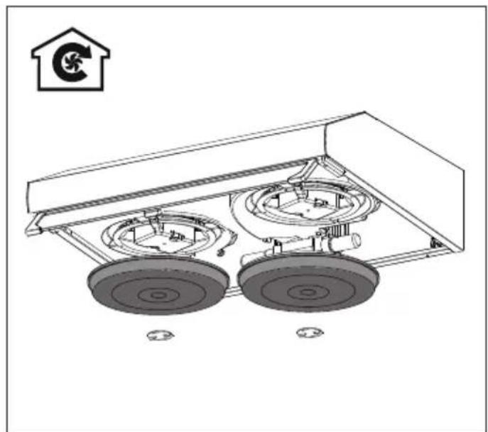
4.2 Changing of carbon filter (Air circulation mode)
The hood can be fitted with an active carbon filter. The carbon filter is applied only in case the hood is not connected to the vent duct.
natural_image
Technical line drawing of a mechanical assembly with two wheels and a central hub (no text or symbols)
WARNING:
• The carbon filter is never washed.
- Replace carbon filters once every 3 months.
• Carbon filter is available from Authorized Services.
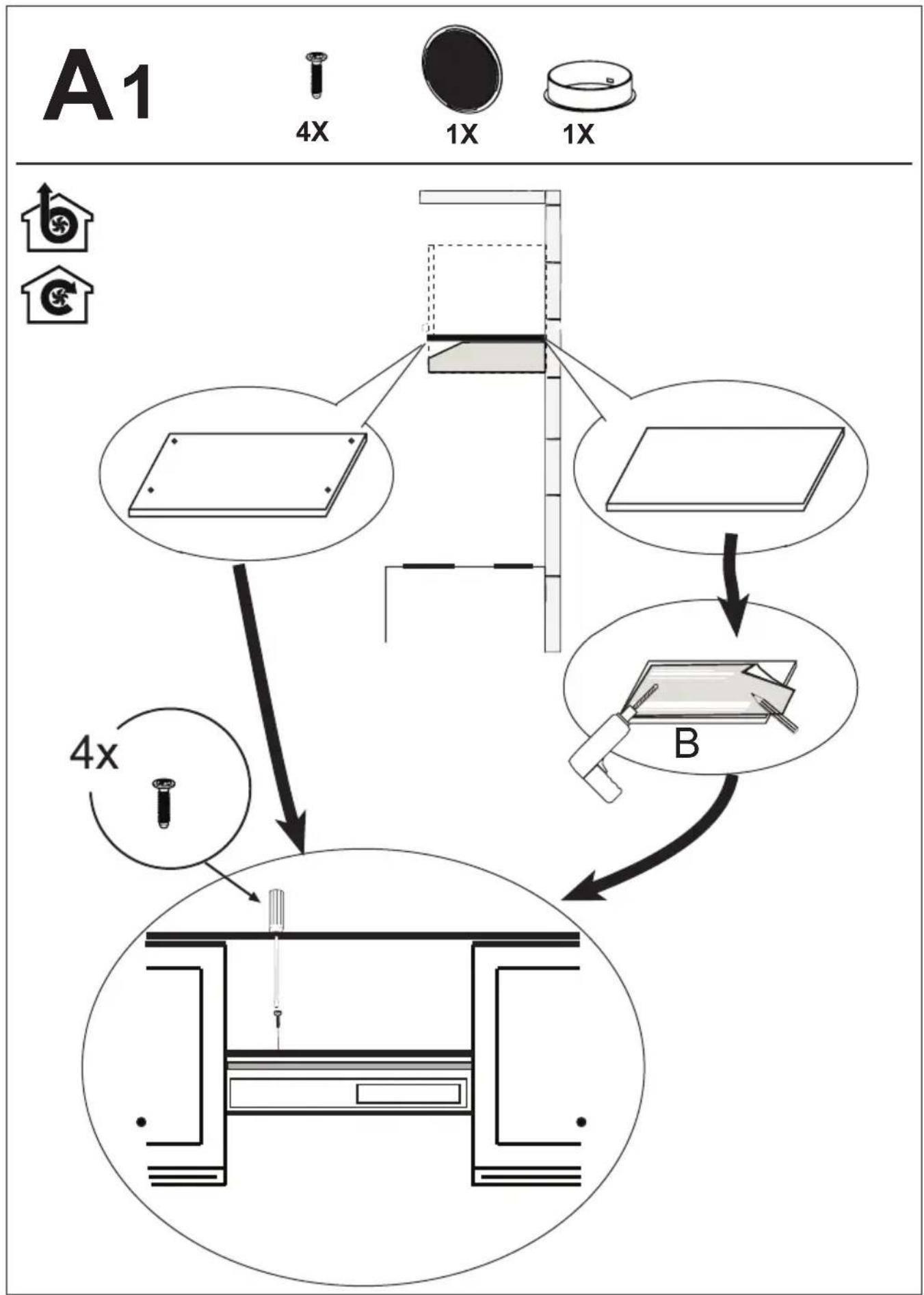
5 Installation of appliance

WARNING: Before starting the installation, read the safety information on user manual.
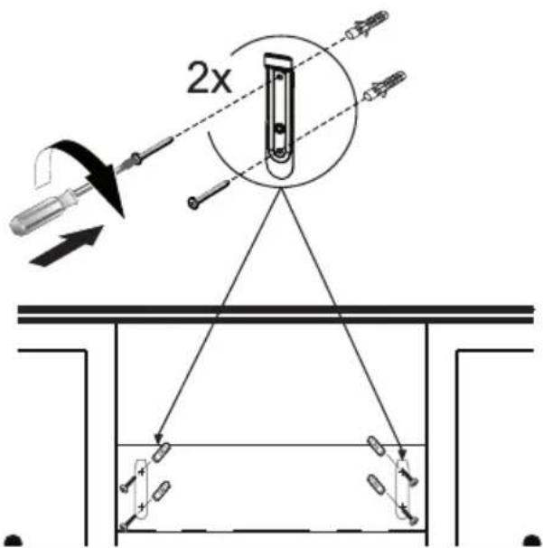
WARNING: Failure to install with screws and stabilizers in accordance with these instructions may result in electric shock.

Please refer to page 222 for the installation guide.
For the installation of the hood, please contact the nearest Authorized Service.
It is the customer's responsibility to prepare the location and electrical installation of the hood.
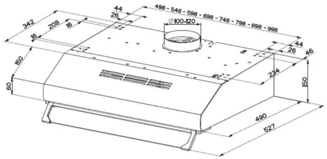
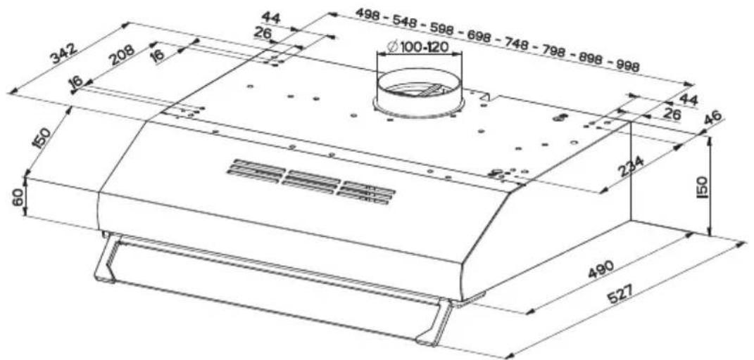
5.1 Position of the appliance
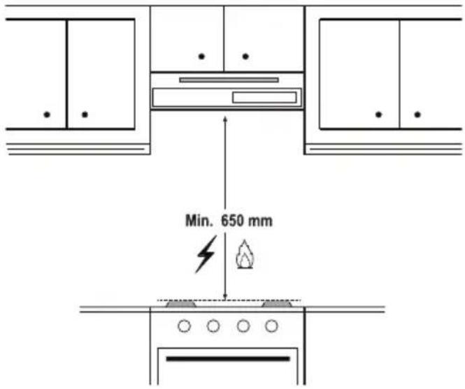
- Distance between the cooker and the cooker hood must be considered prior to assembly. This distance should be 65 cm.
- Distance must be measured from the surface of grate for gas cookers, from surface of glass for electric cookers.
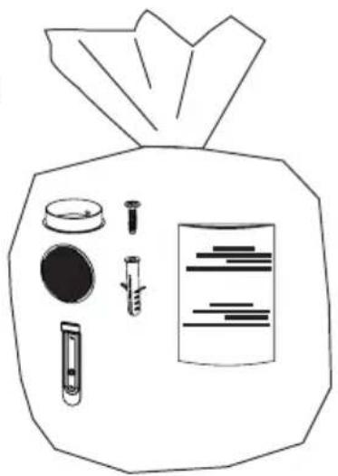
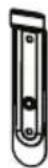
5.2 Installation accessories
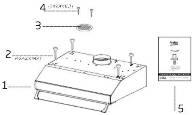
- Hood
- 4 × 4, 2 × 44, 4 screws
- Air outlet grille
- 2 × 2,9 × 12,7 screws
- User manual
5.3 Storage
- If you do not intend to use the appliance for a long time, please store it carefully.
- Please make sure that the appliance is unplugged, cooled down and totally dry.
- Store the appliance in a cool and dry place.
- Keep the appliance out of the reach of children
5.4 Handling and transportation
- During handling and transportation, carry the appliance in its original packaging. The packaging of the appliance protects it against physical damages.
- Do not place heavy loads on the appliance or the packaging. The appliance may be damaged.
- Dropping the appliance will render it non-operational or cause permanent damage.
6 Troubleshooting
| Troubleshooting Reason Help | ||
| The product does not work. | Check your fuse. Your fuse might be | closed, make it work. |
| The product does not work. | Check the electrical connection. | The mains voltage should be between 220-240 V. |
| The product does not work. | Check the electrical connection. | Check if the other products in your kitchen are working or not. |
| The lighting lamp does not work. | Check the electrical connection. | The mains voltage should be between 220-240 V. |
| The lighting lamp does not work. | Check the lamp switch. The lamp switch should be in the “on” position. | |
| The lighting lamp does not work. | Check the lamps. The lamps of the product should not be faulty. | |
| The air intake of the product is poor. | Check the aluminum filter. The aluminum filter should be cleaned at least once a month under normal conditions. | |
| The air intake of the product is poor. | Check the air vent flue. The air vent flue should be in the “on” position. | |
| The air intake of the product is poor. | Check the carbon filter. | For products with carbon filters, the filter should normally be changed every 3 months. |
natural_image
Line drawing of a front-end air conditioner unit with ventilation slots and a circular top (no text or symbols)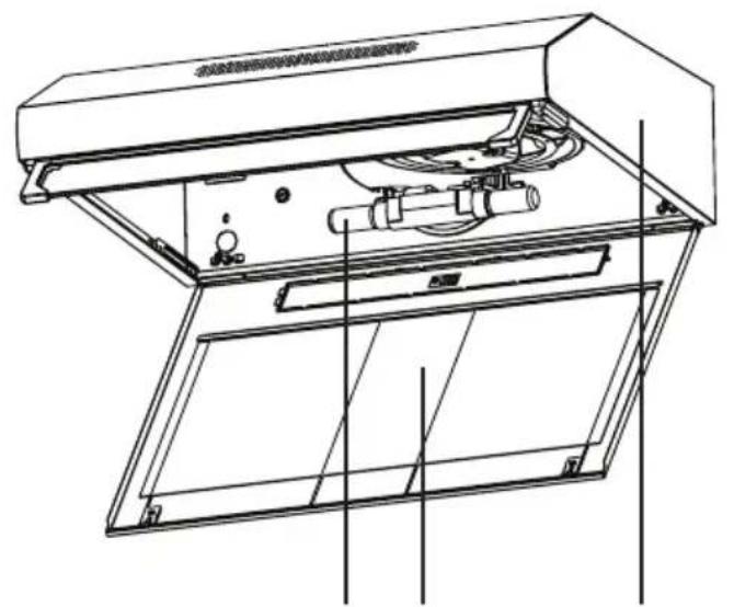
natural_image
Technical line drawing of an open air duct system with internal components (no text or symbols)12345
natural_image
Illustration of a hand using a tool to adjust or install a mechanical component, with no visible text or symbols.| Ampoule | |
| Absorption 4 W | |
| Culot E14 | |
| Voltage 220 – 240 | |
| Code ILCOS D R B B / F | 4 - 2 2 0 - 240-E14-35/100 |
| Dimensions 35x100 mm | |
| Flux lumineux 400 lm | |
| Température de cou-leur corrélée | 3000 K |
natural_image
Technical line drawing of a mechanical assembly with two wheels and a central hub (no text or symbols)
AVERTISSEMENT:
natural_image
Line drawing of a front-end air purifier with ventilation slots and a circular top (no text or symbols)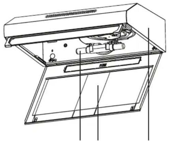
natural_image
Technical line drawing of an open air duct system with internal components and mounting brackets (no text or symbols)12345
natural_image
Illustration of a hand using a handheld device to interact with a device inside a transparent enclosure, showing wiring and components (no text or symbols)natural_image
Technical line drawing of a mechanical assembly with two circular components and a central shaft (no text or symbols)
WARNUNG
natural_image
Line drawing of a front-end air purifier with ventilation slots and a circular top component (no text or symbols)
natural_image
Technical line drawing of an open air duct system with internal components (no text or symbols)12345
natural_image
Technical line drawing of a mechanical assembly with two wheels and a central hub (no text or symbols)
OPGELET
natural_image
Line drawing of a front-end air purifier with ventilation slots and a circular top component (no text or symbols)
natural_image
Technical line drawing of an open air duct system with internal components (no text or symbols)12345

natural_image
Technical diagram of a mechanical assembly with two wheels and a central hub (no text or symbols)
CUIDADO
- Produto
- 4 x 4,2 x 44,4 parafusos
- Grelha de saída de ar
- 2 x 2,9 x 12,7 parafusos
- Manual do Utilizador
5.3 Depozitarea
natural_image
Line drawing of a front-end air purifier with ventilation slots and a circular top component (no text or symbols)
natural_image
Technical line drawing of an open air duct system with internal components (no text or symbols)12345

4.2 Anglies filtro pakeitimas
natural_image
Technical line drawing of a mechanical assembly with two wheels and a central hub (no text or symbols)
DÉMESIO
natural_image
Line drawing of a front-end air purifier with ventilation slots and a circular top component (no text or symbols)
natural_image
Technical line drawing of an open air duct system with internal components (no text or symbols)12345

natural_image
Technical diagram of a mechanical assembly with two wheels and a central shaft (no text or symbols)
VÝSTRAHA
. 1 Výrobok
natural_image
Line drawing of a front-end air purifier with ventilation slots and a circular top (no text or symbols)
natural_image
Technical line drawing of an open air duct system with internal components (no text or symbols)12345

Non-compliance with the provisions associated with the cleaning of the device and replacement of the filters may result in a risk of fire. Therefore, it is recommended to follow the guidelines stated here. The manufacturer is not responsible for the engine damages or fires originating from the improper use.
Čistite koristeći se samo s krpom namočenom u neutralni tekući deterdžent. Ne koristite s alatom ili instrumentima. Ne koristite abrazivne proizvode. Ne koristite alkohol.
4.1. Čišćenje filtra masnoće
Filtar masnoće koristi se za hvatanje čestica ulja u zraku. Filtar masnoće mijenja boju nakon uzastopnog čišćenja. To je normalno i zbog toga ne trebate mijenjati filtre.

Filtar masnoće možete prati u perilici posuđa.

OPREZ: Prilikom normalne primjene filtar masnoće očistite jednom mje-sečno.
natural_image
Technical diagram of a mechanical assembly with two wheels and a central housing (no text or symbols)
OPREZ
- Napa
- 4 × 4,2 × 44,4 vijka
- Rešetka za izlaz zraka
- 2 x 2,9 x 12,7 vijka
- Korisnički priručnik
5.3 Pohrana
natural_image
Line drawing of a front-end air purifier with ventilation slots and a circular top component (no text or symbols)
natural_image
Technical line drawing of an open air duct system with internal components (no text or symbols)12345
natural_image
Technical line drawing of a mechanical assembly with two wheels and a central hub (no text or symbols)natural_image
Line drawing of a front-end air purifier with ventilation slots and a circular top component (no text or symbols)
natural_image
Technical line drawing of an open air duct system with internal components (no text or symbols)12345

- Gövde
- Yağ filtresi
- Aydınlatma
- Kontrol grubu
- Baca
2.2 Teknik veriler
Ampul
natural_image
Technical diagram of a mechanical assembly with two circular components and a central shaft (no text or labels)
DİKKAT
- https://www.instagram.com/bekoturkiye/
- https://twitter.com/beko_tr
- https://www.facebook.com/bekoturkiye/
- https://www.youtube.com/user/BekoChannel
natural_image
Line drawing of a front-end air purifier with ventilation slots and a circular top component (no text or symbols)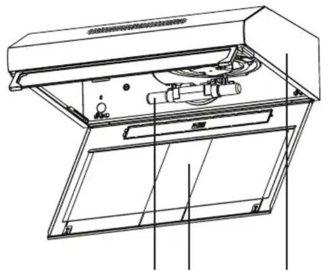
natural_image
Technical line drawing of an open air duct system with internal components (no text or symbols)12345
natural_image
Technical line drawing of a mechanical assembly with two wheels and a central housing (no text or symbols)
ВНИМАНИЕ
natural_image
Simple line icon of a chimney emitting steam (no text or symbols)CFB 9433 XH
RU
natural_image
Line drawing of a front-end air purifier with ventilation slots and a circular top component (no text or symbols)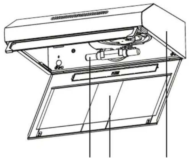
natural_image
Technical line drawing of an open air duct system with internal components (no text or symbols)12345
natural_image
Simple line drawing of a box inside a house-shaped frame with arrows indicating direction (no text or symbols)natural_image
Technical line drawing of a mechanical assembly with two wheels and a central hub (no text or symbols)
ВНИМАНИЕ
The following table provides the original text content: "1. The text content is not explicitly labeled in the image."
natural_image
Line drawing of a front-end air purifier with ventilation slots and a circular vent (no text or symbols)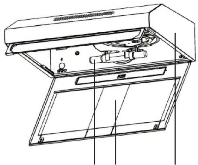
natural_image
Technical line drawing of an open air duct system with internal components and mounting brackets (no text or symbols)12345
natural_image
Technical diagram of a mechanical assembly with two wheels and a central shaft (no text or symbols)natural_image
Line drawing of a front-end air purifier with ventilation slots and a circular vent (no text or symbols)
natural_image
Technical line drawing of an open air duct system with internal components (no text or symbols)12345

natural_image
Technical line drawing of a mechanical assembly with two wheels and a handle (no text or symbols)natural_image
Line drawing of a front-end air purifier with ventilation slots and mounting holes (no text or symbols)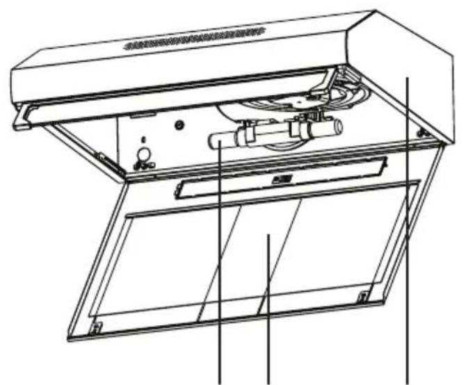
natural_image
Technical line drawing of an open air duct system with internal components (no text or symbols)12345
| Žarnica |  |
| Moč žarnice | 4 W |
| Držalo/vtičnica | E14 |
| Napetost žarnice | 220 - 240 V |
| Velikost | 35x100 mm |
| Koda ILCOS | DRBB/F-4-220-240-E14-35/100 |
| Svetlobni tok 400 lm | |
| Korelirana barvna temperatura | 3000 K |
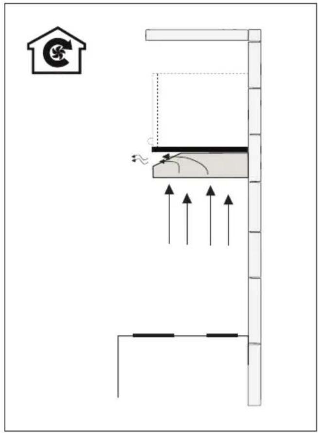
3.5 Operation with chimney connection
• Vapour is extracted through the flue duct, which is fastened to the connection head on the hood.
- The diameter of the flue duct must be the same as the connection ring. In horizontal settings, the pipe has to have a slight upward slope (around 10irc ) so that the air can exit the room easily.
3.6 Operation without chimney connection
Air is filtered through the carbon filter and recirculated in the room. Carbon filter is used when it is impossible to use a flue in the house.
- In flueless use, remove the flaps inside the flue adapter.
- Remove the Grease filter. To install the carbon filter, fit the filter to the tabs by centring it on the plastic piece on both sides of the fan body. tighten it by turning right or left.
- Replace Grease filter.
natural_image
Technical line drawing of a mechanical assembly with two wheels and a central motor (no text or symbols)
POZOR
5.4 Ravnanje in transport
natural_image
Line drawing of a front-end air purifier with ventilation slots and a circular top (no text or symbols)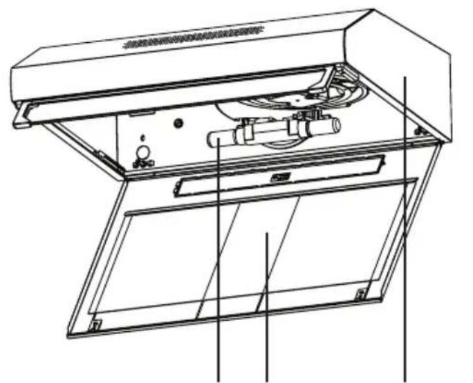
natural_image
Technical line drawing of an open air duct system with internal components and wiring (no text or labels)12345

2.2 技术参数
- 机身
- 油脂滤芯
- 灯具
- 控制板
- 烟筒
natural_image
Illustration of a hand using a tool to adjust or install a mechanical component, with no visible text or symbols.4.2 更换碳滤芯(空气循环模式)
natural_image
Technical line drawing of a mechanical assembly with two wheels and a central hub (no text or symbols)
警告:
natural_image
Line drawing of a front-end air purifier with ventilation slots and a circular vent (no text or symbols)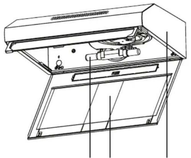
natural_image
Technical line drawing of an open air duct system with internal components and mounting brackets (no text or symbols)12345

- Badan
- Penapis gris
- Pencahayaan
- Panel kawalan
- Cerobong
2.2 Data teknikal
| Model CFB 9433 XH | |
| Voltan bekalan & frekuensi | 220-240V ~ 50 Hz |
| Kuasa Lampu 2 x 4 W | |
| Kuasa Motor 2 x 115 W | |
| Aliran udara – 3. Tahap 380 m3/h | |
| Kelas Penebatan Motor Kelas F | |
| Kelas penebatan Kelas II | |
| Lampu |  |
| Kuasa mentol 4 W | |
| Pemegang/Soket E14 | |
| Voltan mentol 220 - 240 V | |
| Kod ILCOS D R B B / F - | 4 - 2 2 0 -240-E14-35/100 |
| Saiz 35x100 mm | |
| Fluks berkilau 400 lm | |
| Suhu warna terkait 3000 K |
natural_image
Technical line drawing of a mechanical assembly with two wheels and a central rotating component (no text or symbols)
AMARAN:
natural_image
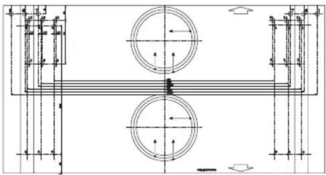
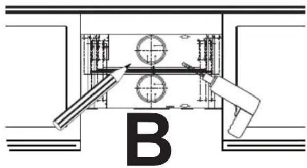
Diagram of a building interior with airflow indicators and structural supports (no text or symbols)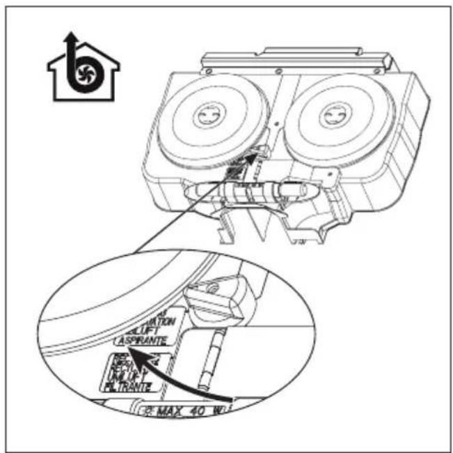

B
natural_image
Technical drawing of a mechanical assembly with circular components and dimension lines (no text or symbols)A
natural_image
Line drawing of a bag with various items including a lid, screwdriver, and paper (no text or symbols)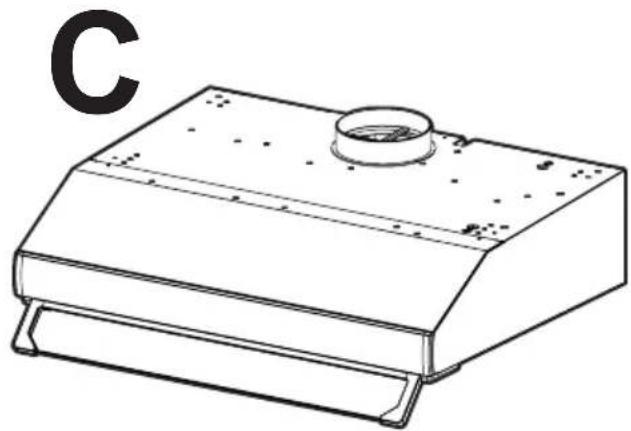
natural_image
Line drawing of a mechanical device with a circular top and side supports (no text or symbols)A1

4X
1X
1X
A2

4X
4X
1X

1X
2X
A3

2X

2X
1X
1X
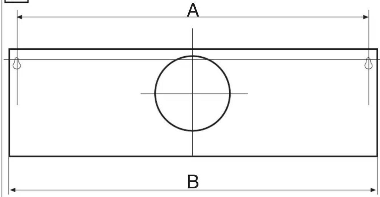
| B mm | 500 550 600 700 760 800 900 1000 1200 | ||||||||
| A mm | 468 518 568 668 728 768 868 968 1168 | ||||||||
flowchart
graph TD
    A["Component 4X"] --> B["Assembly Unit"]
    C["Component 1X"] --> B
    D["Component 1X"] --> B
    B --> E["Assembly Box"]
    E --> F["Final Assembly Unit"]
    G["Component B"] --> F
    H["Component 4X"] --> I["Assembly Unit"]
    I --> J["Final Assembly Unit"]
A2

4X
4X
1X
1X
2X


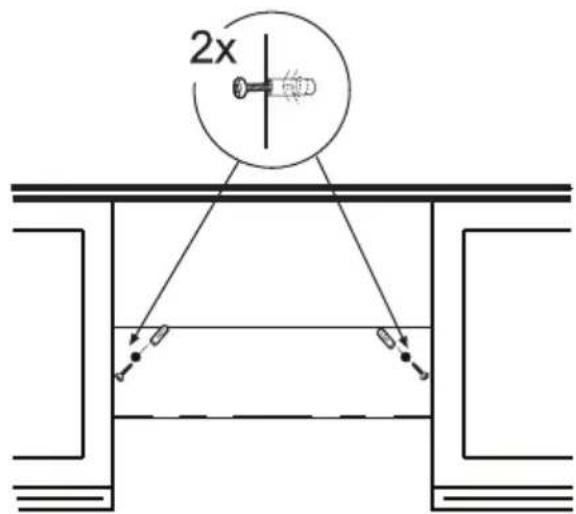
natural_image
Technical diagram showing a mechanical assembly with labeled component B, no readable text or symbols present


A3

2X
2X
1X
1X
1

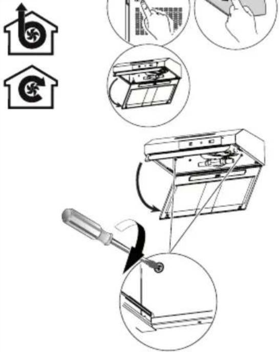
natural_image
Technical diagram showing mechanical assembly with two tool holders and circular components (no text or symbols)3
2

4
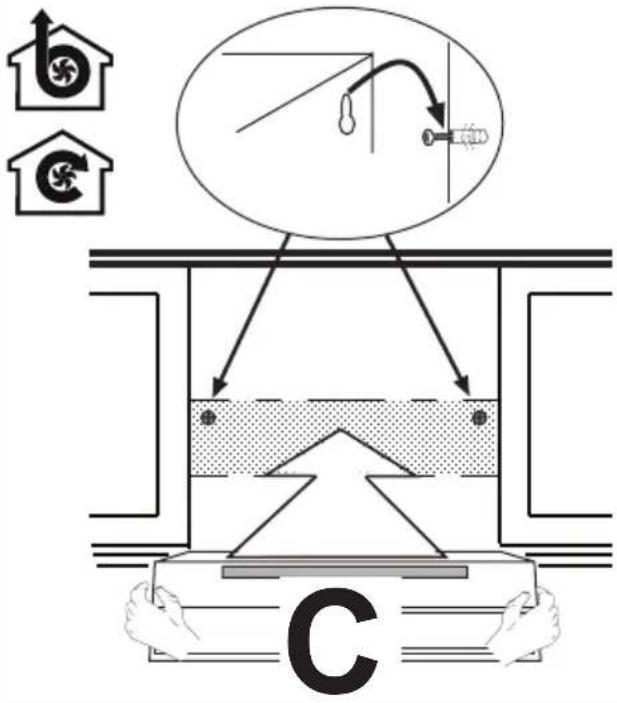
natural_image
Diagram of a vertical structure with arrows indicating forces or movement, no text or symbols present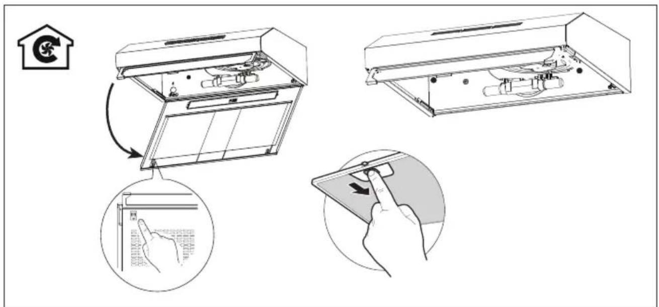
natural_image
Technical line drawing of a mechanical assembly with two wheels and a housing (no text or symbols)Arçelik A.Ş.
Karaağaç Caddesi No: 2-6, 34445,


- CONTENTS
- Please read this user manual first!
- Meanings of the Symbols
- Important safety and environmental instructions
- General Safety
- CAUTION: Accessible parts may become hot when used with coo-king appliances.
- WARNING: Before installing the Hood, remove the protective films.
- Compliance with the WEEE Directive and Disposing of the Waste Product:
- Compliance with RoHS Directive
- Package Information
- General appearance
- Overview
- Technical data
- Using the appliance
- Controls panel
- Efficient use in terms of energy saving
- Operating the Hood
- Lamp replacement
- Operation with flue connection
- Operation without flue connection
- Cleaning and maintenance
- Cleaning of grease filter
- Changing of carbon filter (Air circulation mode)
- WARNING:
- Installation of appliance
- Position of the appliance
- Installation accessories
- Storage
- Handling and transportation
- Troubleshooting
- AVERTISSEMENT:
- WARNUNG
- OPGELET
- CUIDADO
- Depozitarea
- Anglies filtro pakeitimas
- DÉMESIO
- VÝSTRAHA
- Čišćenje filtra masnoće
- OPREZ
- Pohrana
- Teknik veriler
- DİKKAT
- ВНИМАНИЕ
- The following table provides the original text content: "1. The text content is not explicitly labeled in the image."
- Operation with chimney connection
- Operation without chimney connection
- POZOR
- Ravnanje in transport
- 技术参数
- 更换碳滤芯(空气循环模式)
- 警告:
- Data teknikal
- AMARAN:
- A2
- A3
Brand : BEKO
Model : CFB 9433 XH
Category : Range hood