
STN17G - Heating STANLEY - Free user manual and instructions
Find the device manual for free STN17G STANLEY in PDF.
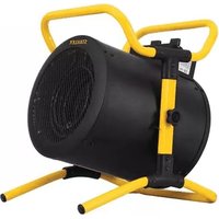
| Product type | Gas construction heater |
| Brand | Stanley |
| Model | STN17G |
| Thermal power | 11.2 - 17.5 kW (depending on model) |
| Maximum heated floor space | Up to 339 m³ |
| Fuel consumption | 0.77 - 1.2 kg/h |
| Power supply | 230 V / 50 Hz |
| Protection rating | IP44 |
| Appliance category | A3 |
| Air temperature class | 44 °C |
| Air flow rate | 510 m³/h |
| Usable gas type | Butane (G30) or Propane (G31) depending on version |
| Gas pressure | 28-30 mbar or 37 mbar depending on country |
| Gas connection | Flexible hose with regulator (EN16129) |
| Dimensions | Not specified |
| Weight | Not specified |
| Main features | Temporary construction heating, piezo ignition, thermocouple safety |
| Safety | Safety thermoswitch, gas leak protection, automatic shutdown in case of overheating |
| Maintenance and cleaning | Internal cleaning with compressed air, checking electrodes and fan |
| Spare parts and repairability | Available parts: motor, igniter, thermocouple, nozzle, control valve |
| Intended use | Temporary construction heating, not suitable as main heating |
Frequently Asked Questions - STN17G STANLEY
User questions about STN17G STANLEY
0 question about this device. Answer the ones you know or ask your own.
Ask a new question about this device
Download the instructions for your Heating in PDF format for free! Find your manual STN17G - STANLEY and take your electronic device back in hand. On this page are published all the documents necessary for the use of your device. STN17G by STANLEY.
USER MANUAL STN17G STANLEY
- BINNENKAST
- BUITENKAST
- GREEP
- BESCHERMPANEL
ACHTER
- SNOER
- STROOMSCHAKELAAR
- INLAATCONNECTOR
- KLEPKNOP
9.VOET
10.HOOGTEREGELAAR
GIDS VOOR PROBLEEMOPLOSSING
Pinnacle Climate Technologies, Inc.
Sauk Rapids, MN 56379 USA
EC REP
Obelis S.A.
© 2018 Stanley Black & Decker, Inc.
STANLEY
ST-40-GFA-E / ST-60V-GFA-E / ST-100V-GFA-E / ST-150V-GFA-E
— AÉROTHERME MOBILE À GAZ —
NE LAISSEZ JAMAIS L'APPAREIL SANS SURVEILLANCE LORSQU'IL FONCTIONNE, QU'IL EST BRANCHÉ À UNE SOURCE D'ALIMENTATION ÉLECTRIQUE ET/OU À UNE SOURCE DE CARBURANT.
Pinnacle Climate Technologies, Inc.
Sauk Rapids, MN 56379 USA
EC REP
Obelis S.A
Domiciliation :
© 2018 Stanley Black & Decker, Inc.
STANLEY
ST-40-GFA-E / ST-60V-GFA-E / ST-100V-GFA-E / ST-150V-GFA-E — MOBILES GASHEIZGEBLASE —

Pinnacle Climate Technologies, Inc.
Sauk Rapids, MN 56379 USA
EC REP
Obelis S.A.
© 2018 Stanley Black & Decker, Inc.
STANLEY
ST-40-GFA-E / ST-60V-GFA-E / ST-100V-GFA-E / ST-150V-GFA-E
— AQUECEDOR PORTÁTIL A GÁS DE AR FORÇADO —

NUNCA DEIXAR O AQUECEDOR SEM VIGILANCA QUANDO ESTIVER COM CHAMA OU LIGADO À CORRENTE ELETRICA OU A UMA FONTE DE COMBUSTIVEL.
Pinnacle Climate Technologies, Inc.
Sauk Rapids, MN 56379 USA
EC REP
Obelis S.A.
Sede social:
© 2018 Stanley Black & Decker, Inc.
STANLEY
ST-40-GFA-E / ST-60V-GFA-E / ST-100V-GFA-E / ST-150V-GFA-E
— CALEFACTOR PORTÁTIL DE AIRE FORZADO DE GAS —

NUNCA DEJE EL CALEFACTOR ENCENDIDO MIENTRAS ESTÉ EN COMBUSTión, CONNECTADO A UNA FUENTE DE ALIMENTACION O MIENTRAS ESTÉ CONECTADO A UNA FUENTE DE COMBUSTIBLE.
ESTE PRODUCTO NO ES ADECUADO PARA FINES DE CALEFACCION PRIMARIA.
Pinnacle Climate Technologies, Inc.
Sauk Rapids, MN 56379 USA
EC REP
Obelis S.A.
Pinnacle Climate Technologies, Inc.
© 2018 Stanley Black & Decker, Inc.
STANLEY
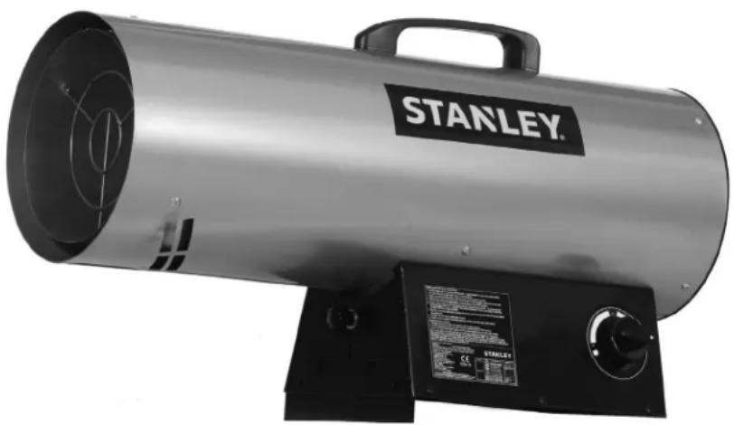
ST-40-GFA-E / ST-60V-GFA-E / ST-100V-GFA-E / ST-150V-GFA-E — MOBILE GAS FIRED FORCED AIR HEATER —

NEVER LEAVE HEATER UNATTENDED WHILE BURNING, CONNECTED TO A POWER SOURCE,OR WHILE CONNECTED TO A FUEL SOURCE.
This product is not suitable for primary heating purposes.
Read The Instruction manual: When this symbol is marked on a product, it means that the instruction manual must be read.

GB
This appliance can be used by children aged from 8 years and above and persons with reduced physical, sensory or mental capabilities or lack of experience and knowledge if they have been given supervision or instruction concerning use of the appliance in a safe way and understand the hazards involved. Children shall not play with the appliance. Cleaning and user maintenance shall not be made by children without supervision.
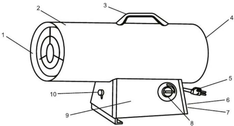
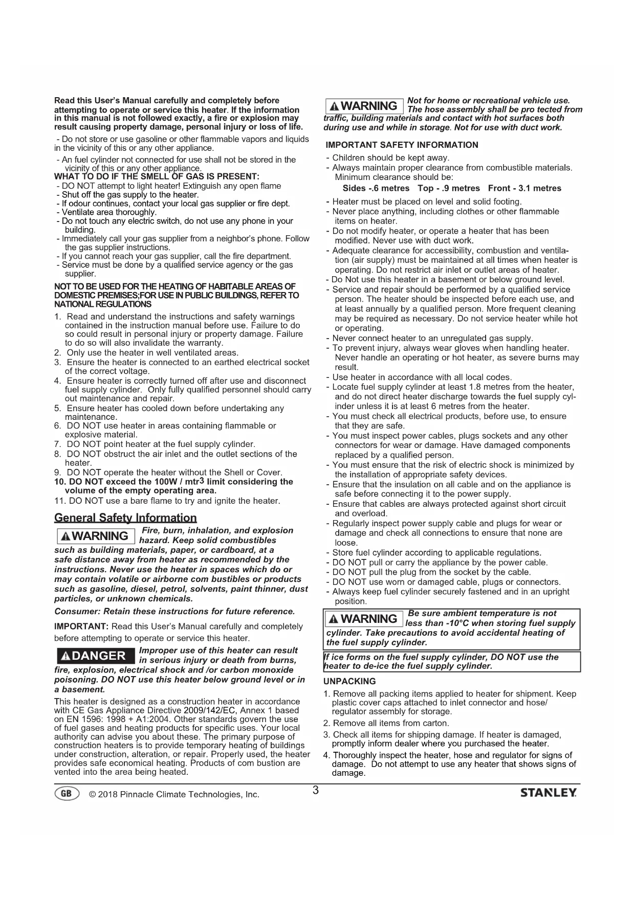
- INNER SHELL
- OUTER SHELL
- HANDLE
- REAR GUARD
- POWER CORD
- POWER SWITCH
- INLET CONNECTOR
- VALVE KNOB
- BASE
10.HEIGHT CONTROLLER
SPECIFICATIONS
Specifications subject to change without notice
| Model # ST-40-GFA-E ST-60V-GFA-E ST-100V-GFA-E ST-150V-GFA-E | ||||
| THERMAL POWER (kW) 12.3 11.2-17.5 | 19.8-28.4 32.5-43.9 | |||
| THERMAL POWER (GRAMS/HR) 862 77 | 0-1200 1451-2041 235 | 9-3039 | ||
| HEATING AREA (m³) | 227 | 339 | 566 | 860 |
| FUEL CONSUMPTION (Kg/HR) | 0.86 | 0.77-1.2 | 1.5-2.0 | 2.4-3.1 |
| MAX OPERATING HOURS | 15 | 16 | 31 | 19 |
| VOLTAGE (V/Hz) | 230 / 50 | 230 / 50 | 230 / 50 | 230 / 50 |
| MOTOR PHASE | 10 | 10 | 10 | 10 |
| INGRESS PROTECTION RATING | 44 | 44 | 44 | 44 |
| AIRFLOW (CMH) | 510 | 510 | 680 | 680 |
| APPLIANCE CATEGORY | A3 | A3 | A3 | A3 |
| AIR TEMPERATURE CLASS | 44°C | 44°C | 44°C | 44°C |
WIRING DIAGRAM
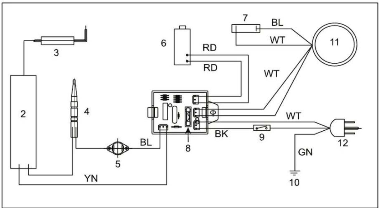
1
1.PANELPCB
- FUSE
BK. BLACK
Read this User's Manual carefully and completely before attempting to operate or service this heater. If the information in this manual is not followed exactly, a fire or explosion may result causing property damage, personal injury or loss of life.
- Do not store or use gasoline or other flammable vapors and liquids in the vicinity of this or any other appliance.
- An fuel cylinder not connected for use shall not be stored in the vicinity of this or any other appliance.
WHAT TO DO IF THE SMELL'OF GAS IS PRESENT:
- DO NOT attempt to light heater! Extinguish any open flame
- Shut off the gas supply to the heater.
- If odour continues, contact your local gas supplier or fire dept.
- Ventilate area thoroughly.
- Do not touch any electric switch, do not use any phone in your building.
- Immediately call your gas supplier from a neighbor's phone. Follow the gas supplier instructions.
-
If you cannot reach your gas supplier, call the fire department.
-
Service must be done by a qualified service agency or the gas supplier.
NOT TO BE USED FOR THE HEATING OF HABITABLE AREAS OF DOMESTIC PREMISES;FOR USE IN PUBLIC BUILDINGS,REFER TO NATIONAL REGULATIONS
- Read and understand the instructions and safety warnings contained in the instruction manual before use. Failure to do so could result in personal injury or property damage. Failure to do so will also invalidate the warranty.
- Only use the heater in well ventilated areas.
- Ensure the heater is connected to an earthed electrical socket of the correct voltage.
- Ensure heater is correctly turned off after use and disconnect fuel supply cylinder. Only fully qualified personnel should carry out maintenance and repair.
- Ensure heater has cooled down before undertaking any maintenance.
- DO NOT use heater in areas containing flammable or explosive material.
- DO NOT point heater at the fuel supply cylinder.
- DO NOT obstruct the air inlet and the outlet sections of the heater.
- DO NOT operate the heater without the Shell or Cover.
- DO NOT exceed the 100W / mtr^3 limit considering the volume of the empty operating area.
- DO NOT use a bare flame to try and ignite the heater.
General Safety Information
WARNING
Fire, burn, inhalation, and explosion hazard. Keep solid combustibles
such as building materials, paper, or cardboard, at a safe distance away from heater as recommended by the instructions. Never use the heater in spaces which do or may contain volatile or airborne com bustibles or products such as gasoline, diesel, petrol, solvents, paint thinner, dust particles, or unknown chemicals.
Consumer: Retain these instructions for future reference.
IMPORTANT: Read this User's Manual carefully and completely before attempting to operate or service this heater.
DANGER
Improper use of this heater can result in serious injury or death from burns,
fire, explosion, electrical shock and/or carbon monoxide poisoning. DO NOT use this heater below ground level or in a basement.
This heater is designed as a construction heater in accordance with CE Gas Appliance Directive 2009/142/EC, Annex 1 based on EN 1596: 1998 + A1:2004 . Other standards govern the use of fuel gases and heating products for specific uses. Your local authority can advise you about these. The primary purpose of construction heaters is to provide temporary heating of buildings under construction, alteration, or repair. Properly used, the heater provides safe economical heating. Products of com bustion are vented into the area being heated.
WARNING Not for home or recreational vehicle use. The hose assembly shall be pro tected from traffic, building materials and contact with hot surfaces both during use and while in storage. Not for use with duct work.
IMPORTANT SAFETY INFORMATION
- Children should be kept away.
- Always maintain proper clearance from combustible materials. Minimum clearance should be:
Sides -.6 metres Top - .9 metres Front - 3.1 metres
- Heater must be placed on level and solid footing.
- Never place anything, including clothes or other flammable items on heater.
- Do not modify heater, or operate a heater that has been modified. Never use with duct work.
- Adequate clearance for accessibility, combustion and ventilation (air supply) must be maintained at all times when heater is operating. Do not restrict air inlet or outlet areas of heater.
-
Do Not use this heater in a basement or below ground level.
-
Service and repair should be performed by a qualified service person. The heater should be inspected before each use, and at least annually by a qualified person. More frequent cleaning may be required as necessary. Do not service heater while hot or operating.
- Never connect heater to an unregulated gas supply.
- To prevent injury, always wear gloves when handling heater. Never handle an operating or hot heater, as severe burns may result.
-
Use heater in accordance with all local codes.
-
Locate fuel supply cylinder at least 1.8 metres from the heater, and do not direct heater discharge towards the fuel supply cylinder unless it is at least 6 metres from the heater.
- You must check all electrical products, before use, to ensure that they are safe.
- You must inspect power cables, plugs sockets and any other connectors for wear or damage. Have damaged components replaced by a qualified person.
- You must ensure that the risk of electric shock is minimized by the installation of appropriate safety devices.
- Ensure that the insulation on all cable and on the appliance is safe before connecting it to the power supply.
- Ensure that cables are always protected against short circuit and overload.
- Regularly inspect power supply cable and plugs for wear or damage and check all connections to ensure that none are loose.
- Store fuel cylinder according to applicable regulations.
- DO NOT pull or carry the appliance by the power cable.
- DO NOT pull the plug from the socket by the cable.
- DO NOT use worn or damaged cable, plugs or connectors.
- Always keep fuel cylinder securely fastened and in an upright position.
WARNING Be sure ambient temperature is not less than -10^ when storing fuel supply cylinder. Take precautions to avoid accidental heating of the fuel supply cylinder.
If ice forms on the fuel supply cylinder, DO NOT use the heater to de-ice the fuel supply cylinder.
UNPACKING
- Remove all packing items applied to heater for shipment. Keep plastic cover caps attached to inlet connector and hose/ regulator assembly for storage.
- Remove all items from carton.
- Check all items for shipping damage. If heater is damaged, promptly inform dealer where you purchased the heater.
- Thoroughly inspect the heater, hose and regulator for signs of damage. Do not attempt to use any heater that shows signs of damage.
WARNING
The gas pressure regulator and hose assembly supplied with the heater must
be used without alteration. INSTALLATION
Minimum ventilation requirements: room volume should not be less than 100m^3 ; minimum ventilation of 25cm^2 per kW of heat input subject to a minimum of 250cm^2 .
- Inspect fuel cylinder and hose connection to appliance to ensure it is in good condition.
- Connect power cord to electrical supply outlet.
- Connect Gas supply hose to heater. (Required hose and regulator is to be 1.5 metres max and 1.0 metre min. in length, and type EN16129). Connect other end (regulator) to a fuel supply cylinder.
WARNING
Be careful to avoid torsional stresses in the flexible tubing (regulator hose).
CAUTION
Use the appropriate fuel supply cylinder listed below.
ST-40-GFA-E:9Kg to 45 Kg fuel cylinder
ST-60V-GFA-E: 9 Kg to 45 Kg fuel cylinder
ST-100V-GFA-E: 9 Kg to 45 Kg fuel cylinder
ST-150V-GFA-E: 9 Kg to 45 Kg fuel cylinder
WARNING
THIS HEATER MUST BE INSTALLED BY COMTETENT PERSONS IN ACCORDANCE WITH SUCH REGULATIONS AS ARE IN FORCE.
NOTE: Optimum efficiency is achieved when the heater uses the appropriate full fuel supply cylinder.
- Slowly open the fuel supply cylinder. Leak test all gas connections with 50/50 soap and water solution prior to start-up to ensure the heater is connected properly. Soap bubbles indicate a gas leak. DO NOT use a match or flame to test for gas leaks.
NOTE: Consult local regulations when planning to install an air temperature control.
| Model No. | Gas Category | Gas Type and inlet Pressure | Destination Country |
| ST-40-GFA-E | DBP(37) | G30 Buance at 37 mbar | PL |
| DBP(57) | G31 Propana at 37 mbar | PL | |
| DBP(100)/G30 | DFG20 Buance at 50 mbar | ||
| DBP(300)/G31 | G31 Propana at 30 mbar | NL, NO, TR | |
| DBP(37)/G31 | G31 Propana at 37 mbar | GB, FR, PT, IE | |
| DBP(50)/G31 | G 31 Propana at 50 mbar | NL, DL | |
| ST-60V-GFA-E ST-100V-GFA-L ST-150V-GFA-F | 13B(28-5057)/G30 | G32 Buance at 28-56 mbarG31 Propana at 37 mbar | GB, FR, IT, PT, IE |
| DBP(500)/G30 | G30 Buance at 30 mbar | NL, NO, SE, CK, R, RO, TR, L | |
| DBP(50)/G30 | G30 Buance at 50 mbar | DE | |
| DBP(57)/G30 | G30 Buance at 37 mbar | PL | |
| DBP(57)/G31 | G31 Propana at 37 mbar | PL | |
| DBP(330)/C51 | G31 Propana at 30 mbar | NL, RO, TR | |
| DBP(37)/G31 | G 31 Propana at 37 mbar | SE, I, K, PI, IL | |
| DBP(50)/C51 | G31 Propana at 50 mbar | NL, SE |
CHANGING FUEL SUPPLY CYLINDERS
- When changing fuel supply cylinders, be sure this is done in a flame-free atmosphere and non-smoking environment.
- When you need to replace your empty cylinder, turn the gas off first.
- Make sure that the heater is extinguished completely.
- Remove the regulator from the empty cylinder and change a new full one.
LIGHTING AND OPERATING INSTRUCTIONS
- Connect power cord to properly earthed socket. Connect heater to a proper fuel supply cylinder.
- Turn gas valve knob on the heater to the "O" (OFF) position.
- Switch the electrical power switch to ON and check if fan is operating correctly.
-
Wait five (5) minutes for any gas to clear. Smell for gas. If none is evident, proceed to the next step.
-
Turn the knob at the fuel supply cylinder counterclockwise to the OPEN position.
- Push in the Gas Valve knob on the heater and hold it at least five (5) seconds. Then turn the knob counterclockwise to the (1 / ) position. This will light the burner. It may be necessary to repeat this process a few times to light the heater.
- Keep the valve knob depressed for at least 30 seconds after the burner is lit. After 30 seconds release the control knob.
- If burner does not stay lit, repeat Steps 5 and 6.
- Check to see the appliance operating pressure is correct according to gas chart (below).
SHUTDOWN INSTRUCTIONS
- Turn gas valve control knob on the heater to the O (OFF) position.
- Turn the control knob at the fuel supply cylinder clockwise to the CLOSED position.
- Disconnect heater from power supply, and disconnect regulator from the fuel supply cylinder.
SERVICING INSTRUCTIONS
These instructions are intended to be used only by competent persons for carrying out all servicing operations authorized by the manufacturer.
All special tools, materials or servicing aids necessary for the correct servicing of the appliance shall be specified. Be sure to check heater for soundness.
- Heater surface temperature must be cold before initiating service, cleaning or storage.
- Maintenance and repair must be carried out by trained personnel only at least 2 times per season.
- Before commencing service maintenance disconnect the unit from the electrical power and the gas supply.
- Check the fuel supply hose condition and change if necessary.
- Check the ignition unit, safety thermostat, and thermocouple condition and ensure that they are clean. If flame pattern appears irregular, check nozzle. Wear eye protection when performing these checks.
- Clean inside the heater unit and the fan blade with compressed air. Heater is operating correctly when fan is running, flame is present and soap test showed no leaks.
WARNING
Disconnect heater from fuel supply cylinder when not in use.
LONG TERM STORAGE
Always disconnect the heater from the fuel supply cylinder before putting the heater into storage. If for any reason the heater is to be stored indoors, the heater MUST be disconnected from the fuel supply cylinder, and the cylinder stored outdoors in a well-ventilated area, and out of the reach of children. If appliance is unable to be left in a safe condition, disconnect the fuel cylinder from appliance and store separately. The plastic valve plug or valve cover supplied with the fuel supply cylinder must be re-installed on the valve to protect the fitting from damage. This appliance is not intended for use by persons (including children) with reduced physical, sensory or mental capabilities, or lack of experience and knowledge, unless they have been given supervision or instruction concerning use of the appliance by a person responsible for their safety. Children should be supervised to ensure that they do not play with the appliance. If the power cord is damaged, it must be replaced by the manufacturer, its service agent or similarly qualified persons in order to avoid a hazard.
- NOTE: In some countries, there may be differences in the requirements listed in this manual. In these cases, contact your local dealer for possible variations from requirements in this manual.
WARNING | RISK OF ELECTRIC SHOCK! DISCONNECT FROM POWER BEFORE MAINTENANCE.
NOTE: This section only applies to heaters sold or used in Great Britain.
This appliance is supplied with a BS1363 3 pin plug fitted with a fuse. Should the fuse require replacement, it must be replaced with a fuse with the proper amp rating. (see Technical Specifications page 2) and approved to BS1362.
In the event the mains plug has to be removed/ replaced for any reason, please note:
IMPORTANT: The wires in the mains lead are colored in accordance with the following code:
Blue - Neutral Brown - Live
Green/Yellow - Earth
As the colors of the wires in the mains lead of this appliance may not correspond with the colored markings identifying the terminals in your plug, proceed as follows:
The blue wire must be connected to the terminal marked with an N or colored black. The brown wire must be connected to the terminal marked with an L or colored red. The green/ yellow wire must be connected to the earthing terminal which is marked with an E or with the earth symbol.
WARNING Never connect live or neutral wires to the earth terminal of the plug.
NOTE: If a moulded plug is fitted and has to be removed take great care in disposing of the plug and severed cable, it must be destroyed to prevent engaging into a socket.
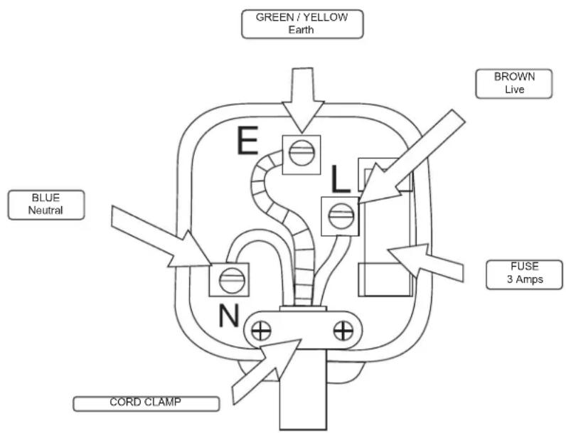
Plug Replacement Wiring Diagram
TROUBLESHOOTING GUIDE
| Problem | Possible Cause Solution | |
| Fan does not turn when electricity is connected. | 1. No electric power to heater.2. Blades of fan in contact with heater housing.3. Fan blades bent.4. Fan motor defective. | 1. Check current at outlet. If voltage is correct, inspect extension and power cords for cuts, frays or breaks.2. Check housing for damage. Be sure there are no dents in the housing obstructing the fan.3. Straighten all fan blades.4. Have motor assembly replaced by a qualified person. |
| Heater will not fire (ignite). | 1. No spark at module.2. Incorrect spark gap.3. Corroded electrode. | 1. Inspect module wire. Re-attach, or tighten if loose. Inspect Spark module and have replaced by a qualified person if necessary.Inspect all other electrical components.2. Set plug gap to 0.16" (4mm).3. Replace spark plug (Multi-Bracket Assembly). |
| Heater stops running by itself. | 1. Temperature inside heater is too high, causing thermal switch to shut down operation.2. Damaged control valve.3. Dust or debris accumulated in heater. | 1. If heater input or output is restricted, the inside temperature can become too hot. Keep the areas in front and behind heater clear of obstructions.2. Have control valve replaced by a qualified person. (Valve Assembly).3. Clean inside of heater. |
| The appliance does not stay lit smoothly or evenly. | 1. The incorrect fuel is used or the incorrect pressure is used. | 1. Check fuel cylinder to assure the correct gas is being used at the correct pressure. |
EXPLODED VIEW
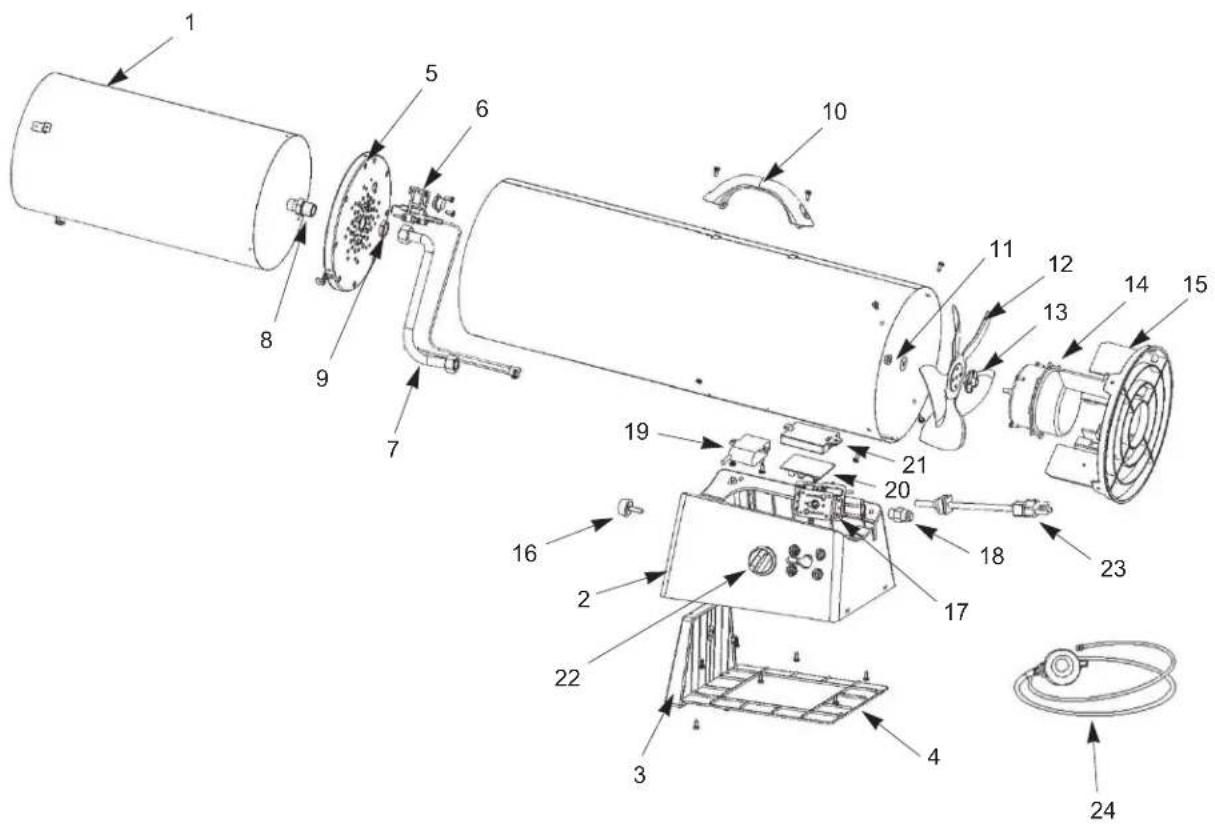
PARTS LIST
| #ST-40-GFA-E / ST-60V-GFA-E / ST-100V-GFA-E / ST-150V-GFA-E | |
| 1 Inner Shell / Combustion Chamber | |
| 2 Base | |
| 3 Height Controller | |
| 4 Base Cover | |
| 5 Inner Shell Cap | |
| 6 Multi bracket | |
| 7 Tubing | |
| 8 Nozzle | |
| 9 Nozzle Nut | |
| 10 Handle | |
| 11 Flange Hex Nut | |
| 12 Fan Blade | |
| 13 Cushion Pad | |
| 14 Motor | |
| 15 | Rear Guard |
| 16 | Round Bolt |
| 17 Valve Assembly | |
| 18 | Inlet Connector |
| 19 | Spark Module |
| 20 | PCB |
| 21 PCB Case | |
| 22 | Control Knob |
| 23 | Power Cord |
| 24 | Regulator and hose |
STANLEY®
SERVICE
| Belgique et LuxembourgBelgiè en Luxembourg | E. Walschaertstraat 142800 MechelenBelgium | www.stanleyworks.beEnduser.be@sbdinc.comBE-NL= +32 15 47 37 65BE-FR = +32 15 47 37 64BE Fax: +32 15 47 37 100 |
| Denmark Roskildevej 22 | 2620 Albertslund | www.stanleyworks.dkkundeservice.dk@sbdinc.comFax: 70224910 |
| Deutschland Richard Klinger Str. 1165510 Idstein | www.stanleyworks.deinfo@sbdinc.deTel: 06126-21-1Fax: 06126-21-2770 | |
| Élàç Hépoc Tónc 2 - Xávi Aβáμ Απρόμρύος-19300 -Aτική - Aτική | www.stanley.grGreece Service@sbdinc.comTηλ: +30 210 8985208Φαε: +30 210 5597598 | |
| Espana Parque de Negocios "Mas Blau"Edificio Muntadas, c/Bergadá, 1, Of. A608820 El Prat de Llobregat (Barcelona) | www.stanleyworks.esrespuesta.postventa@sbdinc.comTel: 934 797 400Fax: 934 797 419 | |
| France 5, allée des hêtresBP 30084, 69579 Limonest Cedex | www.stanleyoutillage.frscufr@sbdinc.comTel: 04 72 20 39 77Fax: 04 72 20 39 00 | |
| SchweizSuisseSwizzeraIn der Luberzen 428902 Urdorf | www.stanleyworks.chverkaufch.sbd@sbdinc.comTel: 044 -755 60 70Fax: 044 -730 70 67 | |
| Ireland 210 Bath Road; Slough, Berks SL1 3YD UK www.stanleytools.co.uk | Tel: +44 (0)1753 511234Fax: +44 (0)1753 512365 | |
| Italia Energypark-Building 03 sud, Via Energy Park6 20871 Vimercate (MB) | www.stanley.itTel. 039-9590-200Fax 039-9590-313 | |
| Nederlands Stanley Black & Decker Netherlands B.V.Postbus 836120 AD Born | www.stanleyworks.nlEnduser.NL@sbdinc.comTel: +31 164 28 30 63NL Fax: +31 164 28 32 00 | |
| Norge Postboks 4613, Nydalen0405 Oslo | www.stanleyworks.nokundeservice.no@sbdinc.comFax: 45 25 08 00 | |
| Österreich Oberlaerstrasse 248A-1230 Wien | www.stanleyworks.deservice.austria@sbdinc.comTel: 01 -66116 -0Fax: 01 -66116 -14 | |
| Portugal Quinta da Fonte - Edificio Q55 D. DinizRua dos Malhões, 2 e 2A - Piso 2 Esquerdo2770 - 071 Paço de Arcos | www.stanleyworks.ptresposta.postenda@sbdinc.comTel: 214 66 75 00Fax: 214 66 75 75 | |
| Suomi PL 4700521 Helsinki | www.stanleyworks.ficustomerservice.fi@sbdinc.comPuh: 010 400 4333 | |
| SverigeBox 94431 22 Möndal | www.stanleyworks.sekunderservice.se@sbdinc.comFax: 31 68 60 08 |
| United Kingdom | 210 Bath Road; Slough, Berks SL1 3YD | www.stanleytools.co.ukTel: +44 (0)1753 511234Fax: +44 (0)1753 512365 |
| Hungary Rotel Kft. | 1163 Budapest,Thokoly ut 17. | www.stanleyworks.hu service@rotelkft.hu Tel+36 1 404-0014 Fax+36 1 403-2260 |
| Czech Republic | BAND SERVIS CZ s.r.o.K Pasekam 4440760 01 Zlin,Czech Republic | www.stanleyworks.czhttp://www.bandservis.cz Tel.: +420 577 008 550 Fax.: +420 577 008 559 |
| Slovakia | BAND SERVIS s.r.o.Paulinska 22917 01 Trnava,Slovakia | www.bandservis.skTel.: +421 335 511 063 Fax.: +421 335 512 624 |
| Poland | Erpatechul. Bakaliowa 2605-080 Mosciska | www.stanleyworks.pl Tel.: +48 22 431 05 00 Fax.: +48 22 468 87 35 |
| Slovenia | G-M&M d.o.o.Brvace 111290 Grosuplje Slovenija | www.g-mm.si gmm@g-mm.si T: +386 01 78 66 500 F: +386 01 78 63 023 |
| Cyprus IOANNOU J. | 4A Ath.Diakou street1046- Nicosa -Cyprus | ioannou.ioannis@cytanet.com.cy Tel: +357 22344302 Fax: +357 22348098 |
| Bosnia-Herzegovina | G-M&M d.o.o.Brvace 111290 GrosupljeSlovenija | www.g-mm.si gmm@g-mm.si T: +386 01 78 66 500 F: +386 01 78 63 023 |
| Bulgaria | TASHEV-GALVING LTD68 KLIMENT OHRIDSKI BLVD.1756 Sofia,Bulgaria | www.tashev-galving.com T: +359 2 700 45 45 4 F: +359 (2) 439 21 12 |
| Croatia G-M&M d.o.o. | Brvace 111290 GrosupljeSlovenija | www.g-mm.si gmm@g-mm.si T: +386 01 78 66 500 F: +386 01 78 63 023 |
| Estonia | AS TallmacMustame tee 44,EE-10621 Tallinn | www.tallmac.ee/est T: +372 6562999 F: +372 6562855 |
| Latvia LIC GOTUS SIA | Ulbrokas Str.LT - 1021 Riga | www.licgotos.lv T: +371 67556949 F: +371 67555140 |
| Lithuania | UAB ELREMTA OUNeries kr. 16ETL - 48402 Kaunas | info@elremta.lt T: +370-685-29035 F: +370-37-406540 |
| Malta | Energypark-Building 03 sud, Via Energy Park6 20871 Vimercate (MB) | www.stanley.it Tel. 039-9590-200 Fax 039-9590-313 |
| Romania | Stanley Black & DeckerPhoenicia Business CenterStrada Turturelelor, nr 11A, Etaj 6, Modul 15, Sector 3 Bucuresti | www.stanleyworks.ro T: +4021.320.61.04/05 F: +4037.225.36.84 |
| Serbia G-M&M d.o.o. | Brvace 111290 GrosupljeSlovenija | www.g-mm.si gmm@g-mm.si T: +386 01 78 66 500 F: +386 01 78 63 023 |
STANLEY®
Manufactured by:
Pinnacle Climate Technologies, Inc.
Sauk Rapids, MN 56379 USA
EC REP
Obelis S.A
Registered Address:
© 2018 Stanley Black & Decker, Inc.


- GIDS VOOR PROBLEEMOPLOSSING
- STANLEY
- GB
- WIRING DIAGRAM
- WHAT TO DO IF THE SMELL'OF GAS IS PRESENT:
- NOT TO BE USED FOR THE HEATING OF HABITABLE AREAS OF DOMESTIC PREMISES;FOR USE IN PUBLIC BUILDINGS,REFER TO NATIONAL REGULATIONS
- General Safety Information
- WARNING
- DANGER
- IMPORTANT SAFETY INFORMATION
- UNPACKING
- be used without alteration. INSTALLATION
- CAUTION
- CHANGING FUEL SUPPLY CYLINDERS
- LIGHTING AND OPERATING INSTRUCTIONS
- SHUTDOWN INSTRUCTIONS
- SERVICING INSTRUCTIONS
- LONG TERM STORAGE
- WARNING | RISK OF ELECTRIC SHOCK! DISCONNECT FROM POWER BEFORE MAINTENANCE.
- EXPLODED VIEW
- PARTS LIST
- STANLEY®
- SERVICE
Brand : STANLEY
Model : STN17G
Category : Heating