VDPC145 - Controller HQ Power - Free user manual and instructions
Find the device manual for free VDPC145 HQ Power in PDF.

| Product type | DMX Controller |
| Number of DMX channels | 192 |
| Number of controllable devices | 12 (up to 16 channels each) |
| Memory banks | 30 banks of 8 scenes |
| Programmable chases | 6 chases, up to 240 scenes per chase |
| Display | 4-digit LED display |
| Power supply | Adapter 9-12V DC, 300 mA minimum |
| Dimensions | 482 x 132 x 73 mm |
| Weight | 2.5 kg |
| MIDI input | Yes (MIDI IN) |
| DMX output | 3-pin XLR (DMX OUT) |
| DMX polarity selector | Yes |
| Microphone input | Built-in for sound triggering |
| Adjustable chase speed | 0.1 sec to 10 min |
| Adjustable fade time | 0 to 30 seconds |
| Level display | 0-255 or 0-100% |
| Blackout function | Yes, reduces all channels to 0% |
| Operating modes | Manual, Auto, Music, MIDI, Chase |
| Operating temperature | 5°C to 35°C |
| Cleaning | Damp cloth, avoid alcohol and solvents |
| Maintenance | Check screws and nuts, avoid corrosion |
| Safety | Protect from moisture, disconnect before opening |
| Warranty | 24 months for private use (Velleman conditions) |
Frequently Asked Questions - VDPC145 HQ Power
User questions about VDPC145 HQ Power
0 question about this device. Answer the ones you know or ask your own.
Ask a new question about this device
Download the instructions for your Controller in PDF format for free! Find your manual VDPC145 - HQ Power and take your electronic device back in hand. On this page are published all the documents necessary for the use of your device. VDPC145 by HQ Power.
USER MANUAL VDPC145 HQ Power
text_image
192-CHANNEL DAC CONTROLLER SPEED 10kHz SPEED 10kHz SPEED 10kHz SPEED 10kHz SPEED 10kHz SPEED 10kHz SPEED 10kHz SPEED 10kHz SPEED 10kHz SPEED 10kHz SPEED 10kHz SPEED 10kHz SPEED 10kHz SPEED 10kHz SPEED 10kHz Pulse 1 0.18EC Pulse B Pulse Dosept Pulse S Pulse T Pulse U Pulse V Pulse W Pulse X Pulse Y Pulse Z Pulse AA Pulse AB Pulse AC Pulse AD Pulse AE Pulse AF Pulse AG Pulse AH Pulse AI Pulse AJ Pulse AK Pulse AL Pulse AM Pulse AN Pulse AO Pulse AP Pulse AQ Pulse AR Pulse AS Pulse AT Pulse AU Pulse AV Pulse AW Pulse AX Pulse AY Pulse AZY Pulse BAZY Pulse BZY Pulse BCY Pulse BDY Pulse BEZY Pulse BFY Pulse BGY Pulse BHY Pulse BIY Pulse BJY Pulse BKY Pulse BLY Pulse BMY Pulse BNY Pulse BOY Pulse BPY Pulse BPZY Pulse BPYCCY Pulse BPZYCCY Pulse BPZYACY Pulse BPZYACYCCY Pulse BPZYACYACYCCY Pulse BPZYACYACYACYCCY Pulse BPZYACYACYACYACYCCY Pulse BPZYACYACYACYACYACYCCY Pulse BPZYACYACYACYACYACYACYCCY Pulse BPZYACYACYACYACYACYACYACYCCY Pulse BPZYACYACYACYACYACYACYACYACYCCYUSER MANUAL
GEBRUIKERSHANDLEIDING
NOTICE D'EMPLOI
MANUAL DEL USUARIO
BEDIENUNGSANLEITUNG
INSTRUKCJA OBSŁUGI
CE
1. Introduction & Features
To all residents of the European Union
Important environmental information about this product

This symbol on the device or the package indicates that disposal of the device after its lifecycle could harm the environment.
Do not dispose of the unit (or batteries) as unsorted municipal waste; it should be taken to a specialized company for recycling.
This device should be returned to your distributor or to a local recycling service.
Respect the local environmental rules.
If in doubt, contact your local waste disposal authorities.
Thank you for buying the VDPC145! Please read the manual carefully before bringing this device into service. This is a 192-channel DMX controller, capable of controlling 12 devices with up to 16 channels. The device features 30 banks of 8 scenes each, 6 chases for scene programming and a 4-digit LED display. Check carefully for damage caused by transportation. Consult your dealer and don't install this device if it has been damaged in transit.
2. Safety Instructions

Be very careful during the installation: touching live wires can cause life-threatening electroshocks.

Keep this device away from rain and moisture.

Unplug the mains lead before opening the housing.
- A qualified technician should install and service this device.
- Damage caused by disregarding certain guidelines in this manual is not covered by the warranty and the dealer will not accept responsibility for the ensuing defects or problems.
- Do not switch the device on immediately if it has been exposed to changes in temperature. Protect the device against damage by leaving it switched off until it has reached room temperature.
- Make sure that the available voltage does not exceed the voltage stated in the specifications of this manual.
- Do not crimp the power cord and protect it against damage from sharp edges. Ask an authorised dealer to replace the cord if necessary.
- Always disconnect the device from the mains when it is not in use or when you wish to clean it. Only handle the power cord by the plug. Never pull out the plug by tugging the power cord.
- Note that damage caused by user modifications to the device are not covered by the warranty. Keep the device away from children and unauthorised users.
3. General Guidelines
- This device is a lighting controller for professional use on stage, in discos, theatres, etc. The VDPC145 should only be used indoors with the included adapter working on an alternating current of max. 230VAC / 50Hz.
- Do not shake the device. Avoid brute force when installing or operating the device.
- Select a location where the device will be protected against extreme heat, moisture and dust.
- Do not use or transport the device under temperatures < 5^ or >35^ .
- Familiarise yourself with the functions of the device before actually using it. Do not permit operation by unqualified people. Any damage that may occur will probably be due to unprofessional use of the device.
- Use the original packaging if the device is to be transported.
- Note that all modifications of the device are forbidden for safety reasons.
- Do not remove the serial number sticker from the device as doing so will void the warranty. Only use the device for its intended purpose. All other uses may cause short circuits, burns, electroshocks, lamp explosions, crashes, etc. Using the device in an unauthorised way will void the warranty.
VDPC145_v2 VELLEMAN 2
4. Description
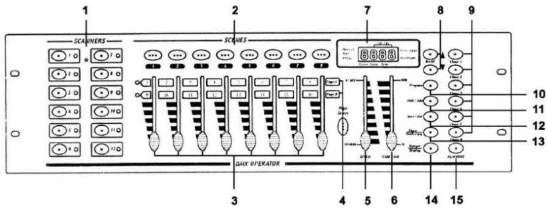
a) Front Panel
Fig. 1
text_image
1 2 7 8 9 SCAINERS SCRAMES 10 11 12 13 3 4 5 6 14 15 DALK OPERATOR Page 1 Page 2 Page 3 Page 4 Page 5 Page 6 Page 7 Page 8 Page 9 ALABORATE SPEED LUM AVG AIR AIR 1 AIR 2 AIR 3 AIR 4 AIR 5 AIR 6 AIR 7 AIR 8 AIR 9- Scanner Buttons
| SCANNERS | CHANNEL |
| 1 | 1-16 |
| 2 | 17-32 |
| 3 | 33-48 |
| 4 | 49-64 |
| 5 | 65-80 |
| 6 | 81-96 |
| 7 | 97-112 |
| 8 | 113-128 |
| 9 | 129-144 |
| 10 | 145-160 |
| 11 | 161-176 |
| 12 | 177-192 |
Press the button to activate the selected scanner (LED is lit). All appropriate channels are ready for use and can be adjusted.
2. Scene Buttons (1 - 8)
Press a button to run or store a scene. The second digit of the LED display shows scenes 1-8.
3. Faders (1 - 8)
Use the faders to adjust the output level of a DMX channel from 0 to 255. The value will appear on the LCD display.
4. Page Select
Press this button to switch between page A (the first 8 channels) and page B (the next 8 channels) of a device.
5. Speed Slider
Adjust the chase speed with this slider (0.1 sec. - 10 min.)
6. Fade Time Slider
Adjust the fade time with this slider (0 - 30 sec.)
7. LED Display
Displays all necessary information
8. Bank Buttons
Press ▲ or ▼ to select a bank. The third and fourth digit on the LED display make up the bank number (01 - 30).
9. Chase (1 - 6)
Press a button to run or store a chase. The first digit on the LED display is the chase number (1 - 6).
10. Program
The device is in MANUAL RUN mode when you turn it on. Hold the PROGRAM button for 2 seconds. The LED flashes and SCENE and CHASE are ready to be programmed. Hold PROGRAM for 2 seconds again to activate the BLACKOUT mode. The PROGRAM LED extinguishes and the BLACKOUT indication is lit. Press the BLACKOUT button to return to the MANUAL RUN mode. The blackout LED goes out.
11. MIDI / ADD
MIDI : Hold the MIDI button for two seconds when the device is in RUN mode. The third and fourth digit of the LED display start to flash. Select a MIDI channel with ▲ or ▼ . Press any button other than ▲ or ▼ to end the MIDI channel setting.
ADD : Push this button to add lines in a program while the device is in the programming mode.
12. AUTO / DEL
AUTO : Press this button while the device is in the RUN mode. The AUTO TRIGGER LED is lit, indicating that the AUTO RUN mode has been activated. Press the AUTO button again to deactivate the auto run mode.
DEL : Push this button to delete a scene or a chase while in the programming mode.
13. MUSIC / BANK COPY
MUSIC : Push this button while in the device is in RUN mode. The MUSIC mode is now activated and the MUSIC TRIGGER LED is lit. Press this button again to deactivate the MUSIC mode.
BANK COPY : Press this button to copy a bank when the device is in the programming mode.
14. TAP SYNC / DISPLAY
TAP SYNC : When the device is in the AUTO RUN mode, the running speed depends on the duration of the interval between the last two times you pressed the TAP SYNC/DISPLAY button.
DISPLAY : Press this button to choose between 00-255 or 0%-100% display for the faders.
15. BLACKOUT
Press this button to set the output of all channels to 0%. This does NOT affect the other functions of the device. Press this button again to deactivate the blackout mode.
Fig. 2
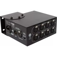
b) Back Panel
- MIDI IN
- DMX POLARITY SELECT
- DMX OUT (3-pole XLR)
- DC input (9-12V, 300mA)
text_image
MIDI IN DMX POLARITY SELECT 1. Ground 2. Data - 3. Data + 17 18 19 DC INPUT 9V - 12V, 300mA min.c) Connections
The manufacturer is not responsible for damage caused by improper connections.
Connect the supplied adapter with the DC jack and connect the other end with a mains outlet.
The device has a built-in microphone for sound control. Use the MIDI input if you want sound control by an external source.
5. Operating Instructions
Programming Scenes
Hold the PROGRAM button for 2 seconds to activate the PROGRAM mode. The PROGRAM LED will flash.
a) Scene Programming
- Press the desired SCANNER button to select a device
- It is possible to select several devices and control them simultaneously.
- Adjust the appropriate faders to the desired output level.
- Press the MIDI/ADD button
- Select the desired bank with ▲ or ▼.
- Press a SCENE button to store this scene in the selected bank.
b) Scene Editing
- Select the desired scene of a bank by pressing the corresponding SCENE button.
- Adjust the faders
- Press the MIDI/ADD button
- Press SCENE again to store the new settings
c) Copying a Scanner
- Hold the button for the currently selected scanner
- Press the button for the scanner you want to copy the settings of the first scanner to.
- Release both buttons.
d) Copying a Scene
- Press the SCENE button for the scene you wish to copy
- Press the MIDI/ADD button.
- Select a bank with ▲ or ▼ and press the button for the scene you want to copy the settings of the first scene to.
e) Deleting a Scene
- Select the desired scene by pressing the corresponding scene button.
- Press the button for the scene to be deleted while holding the AUTO/DEL button.
f) Clearing all scenes
- Press PROGRAM and ▼ while deactivating the device.
- Turn the device back on.
g) Copying a Bank
- Select the desired bank.
- Press the MIDI/ADD button.
- Select the bank you wish to copy with ▲ or ▼.
- Press the MUSIC/BANKCOPY button.
h) Deleting a Bank
- Select the bank to be deleted.
- Press AUTO/DEL and MUSIC/BANKCOPY buttons simultaneously.
Programming Chases
Hold the PROGRAM button for 2 seconds to activate the programming mode. The programming LED will start to flash. One chase can contain up to 240 scenes and the scenes are run in the programmed order. The first scenes to be run will be the first that were programmed.
a) Programming a Chase
- Select a chase containing programmed scenes by pressing the appropriate CHASE button.
- Select a scene from a bank with ▲ or ▼ and press the corresponding SCENE button.
- Press the MIDI/ADD button.
b) Copying all Scenes from a Bank to a Chase
- Select the desired bank with ▲ or ▼.
- Press the MUSIC/BANKCOPY button.
- Press the MIDI/ADD button.
c) Adding a Step to a Chase
Example : inserting a scene as step 10 in an existing 15-step chase.
- Press TAPSYNC/DISPLAY to display the CHASE and its STEP on the LCD.
- Select STEP 9 with ▲ or ▼.
- Press MIDI/ADD, making the step turn to 10.
- Select a scene from the bank with ▲ or ▼ and then press the corresponding SCENE button.
- Press MIDI/REC to add the new scene to the newly inserted step. The previous step 10 becomes step 11, etc..
d) Deleting a Step from a Chase
Example : deleting step 10.
- Press TAPSYNC/DISPLAY to display the CHASE and its STEP on the LCD.
- Select step 10 with ▲ or ▼ .
- Press AUTO/DEL : step 11 becomes step 10, step 12 becomes step 11, etc.
e) Deleting a Chase
- Select the desired chase with the CHASE button.
- Press AUTO/DEL while holding that CHASE button.
f) Clearing all Chases
- Press ▼ and AUTO/DEL simultaneously while deactivating the device.
- Turn the device back on.
Running Scenes
The device is in RUN mode when it is turned on. Hold the PROGRAM button for 2 seconds to enter the PROGRAM mode. Subsequently, the device automatically switches to the BLACKOUT mode. Press the BLACKOUT button to enter the RUN mode. Only those scenes programmed into a bank can be run.
a) Manual Run
- Make sure AUTO TRIGGER and MUSIC TRIGGER are off.
- Select a bank with ▲ or ▼ or through MIDI signals.
- Press the desired SCENE button.
b) Auto Run
- Press AUTO/DEL. The AUTO TRIGGER LED comes on.
- Press TAPSYNC/DISPLAY. Press it again after an interval of your choice. The interval between the two presses is the assigned speed of AUTO RUN (max. 10 min.). If you press more than twice, only the last two presses are taken into account.
- Select a bank with ▲ or ▼ or through MIDI signals.
- Press AUTO/DEL again to leave the AUTO RUN mode.
c) Music Run
- Press MUSIC/BANKCOPY. The MUSIC TRIGGER LED is lit.
- Select a bank with ▲ or ▼ or through MIDI signals.
- Press MUSIC/BANKCOPY again to leave the MUSIC RUN mode.
d) Midi Run
The scenes from a bank are selected through the MIDI input whenever the device is in the MANUAL RUN, AUTO RUN or MUSIC RUN mode.
e) Chase Run
To use a chase run you have to make programmes first. A chase run can be activated via the MANUAL RUN, AUTO RUN, MUSIC RUN and MIDI RUN modes.
Select the desired chase with the CHASE button. The selected chase is displayed on the LCD.
f) Fade Time Control
Adjust the fade time with the slider.
MIDI Channel Settings
The correct bank is selected by means of the NOTE ON signal coming from the MIDI device e.g. a keyboard.
| BANK | NOTE | NUMBER |
| BANK 1 | 00 Turn on/off SCENE 1 | |
| 01 Turn on/off SCENE 2 | ||
| 02 Turn on/off SCENE 3 | ||
| 03 Turn on/off SCENE 4 | ||
| 04 Turn on/off SCENE 5 | ||
| 05 Turn on/off SCENE 6 | ||
| 06 Turn on/off SCENE 7 | ||
| 07 Turn on/off SCENE 8 | ||
| BANK 2 | 08 Turn on/off SCENE 1 | |
| 09 Turn on/off SCENE 2 | ||
| 10 Turn on/off SCENE 3 | ||
| “ | “ | |
| BANK 15 | 112 Turn on/off SCENE 1 | |
| 113 Turn on/off SCENE 2 | ||
| 114 Turn on/off SCENE 3 | ||
| 115 Turn on/off SCENE 4 | ||
| 116 Turn on/off SCENE 5 | ||
| 117 Turn on/off SCENE 6 | ||
| 118 Turn on/off SCENE 7 | ||
| 119 Turn on/off SCENE 8 | ||
| CHASE | 120 Turn on/off SCENE 1 | |
| 121 Turn on/off SCENE 2 | ||
| 122 Turn on/off SCENE 3 | ||
| 123 Turn on/off SCENE 4 | ||
| 124 Turn on/off SCENE 5 | ||
| 125 Turn on/off SCENE 6 | ||
| 126 | BLACKOUT | |
6. Cleaning and Maintenance
- All screws for installing the devices or parts of the device have to be screwed down tight and must not be corroded.
- The housing, mounting supports and connections should not be modified or tampered with e.g. do not drill extra holes in mounting supports, do not change the location of the connections, etc.
- The electric power supply cables must be undamaged. Have the device installed by a qualified technician.
- Disconnect the device from the mains prior to maintenance activities.
- Wipe the device regularly with a moist cloth. Do not use alcohol or solvents.
- Entrust a qualified technician with the maintenance of this device. Contact your dealer for spare parts if necessary.
7. Technical Specifications
Power Supply AC/DC adapter 9-12Vdc/300mA (supplied)
Number of DMX Channels 192
Max. Cable Length 100m
Music Control via built-in microphone or MIDI interface
Dimensions 482 x 132 x 73mm
Weight
2.5kg
The information in this manual is subject to change without prior notice.
VDPC145_v2 VELLEMAN 8
CC/CA 9Vcc/300mA (inc
text_image
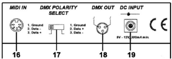
1 SCANERS 2 SCANES 7 8 9 3 4 5 6 7 8 10 11 12 13 SCANERS CNC CNC CNC CNC CNC CNC CNC CNC CNC CNC CNC CNC CNC CNC CNC CNC CNC CNC CNC CNC CNC CNC CNC CNC CNC CNC CNC CNC CNC CNC CNC CNC CNC CNC- Botones escáner
| ESCÁNERES | CANAL |
| 1 | 1-16 |
| 2 | 17-32 |
| 3 | 33-48 |
| 4 | 49-64 |
| 5 | 65-80 |
| 6 | 81-96 |
| 7 | 97-112 |
| 8 | 113-128 |
| 9 | 129-144 |
| 10 | 145-160 |
| 11 | 161-176 |
| 12 | 177-192 |
Velleman® Service and Quality Warranty
Velleman ^® has over 35 years of experience in the electronics world and distributes its products in more than 85 countries.
All our products fulfil strict quality requirements and legal stipulations in the EU. In order to ensure the quality, our products regularly go through an extra quality check, both by an internal quality department and by specialized external organisations. If, all precautionary measures notwithstanding, problems should occur, please make appeal to our warranty (see guarantee conditions).
General Warranty Conditions Concerning Consumer Products (for EU):
- All consumer products are subject to a 24-month warranty on production flaws and defective material as from the original date of purchase.
- Velleman® can decide to replace an article with an equivalent article, or to refund the retail value totally or partially when the complaint is valid and a free repair or replacement of the article is impossible, or if the expenses are out of proportion.
You will be delivered a replacing article or a refund at the value of 100% of the purchase price in case of a flaw occurred in the first year after the date of purchase and delivery, or a replacing article at 50% of the purchase price or a refund at the value of 50% of the retail value in case of a flaw occurred in the second year after the date of purchase and delivery.
• Not covered by warranty:
- all direct or indirect damage caused after delivery to the article (e.g. by oxidation, shocks, falls, dust, dirt, humidity...), and by the article, as well as its contents (e.g. data loss), compensation for loss of profits;
- frequently replaced consumable goods, parts or accessories such as batteries, lamps, rubber parts, drive belts... (unlimited list);
- flaws resulting from fire, water damage, lightning, accident, natural disaster, etc.;
- flaws caused deliberately, negligently or resulting from improper handling, negligent maintenance, abusive use or use contrary to the manufacturer's instructions; - damage caused by a commercial, professional or collective use of the article (the warranty validity will be reduced to six (6) months when the article is used professionally);
- damage resulting from an inappropriate packing and shipping of the article;
- all damage caused by modification, repair or alteration performed by a third party without written permission by Velleman ^29 .
- Articles to be repaired must be delivered to your Velleman® dealer, solidly packed (preferably in the original packaging), and be completed with the original receipt of purchase and a clear flaw description.
- Hint: In order to save on cost and time, please reread the manual and check if the flaw is caused by obvious causes prior to presenting the article for repair. Note that returning a non-defective article can also involve handling costs.
• Repairs occurring after warranty expiration are subject to shipping costs.
• The above conditions are without prejudice to all commercial warranties.
The above enumeration is subject to modification according to the article (see article's manual).