LEDC09 - Controller HQ Power - Free user manual and instructions
Find the device manual for free LEDC09 HQ Power in PDF.

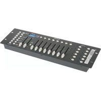
| Product type | DMX RGB+W Controller for LED Strips |
| Brand | HQ Power |
| Model | LEDC09 |
| Power supply | 12-24 VDC (not included) |
| DMX channels | 4 (red, green, blue, white) |
| Output current | 4 x 4 A |
| Gray levels | 256 (8-bit) |
| PWM frequency | ± 2600 Hz |
| Input signal | DMX512 |
| Power output | 12 V < 192 W, 24 V < 384 W |
| DMX input/output connectors | 3-pin XLR and RJ45 (8P8C) |
| Output terminals | COM, CH1 (red), CH2 (green), CH3 (blue), CH4 (white) |
| Operating modes | Test (static color, color change, fade), DMX |
| DMX addressing | DIP switches 1-9 |
| Dimensions | 165 x 68 x 40 mm |
| Weight | 310 g |
| Safety | Protection against rain, moisture, water splashes; disconnect before cleaning; no user-serviceable parts; installation by qualified technician |
| Maintenance | Clean with a dry cloth after disconnecting; protect from dust and extreme temperatures |
| Warranty | 24 months for manufacturing defects (see conditions in manual) |
| General information | Use with original accessories; modifications prohibited |
Frequently Asked Questions - LEDC09 HQ Power
User questions about LEDC09 HQ Power
0 question about this device. Answer the ones you know or ask your own.
Ask a new question about this device
Download the instructions for your Controller in PDF format for free! Find your manual LEDC09 - HQ Power and take your electronic device back in hand. On this page are published all the documents necessary for the use of your device. LEDC09 by HQ Power.
USER MANUAL LEDC09 HQ Power
text_image
DMS12 DDC000 INPUT OUTPUT INPUT:DC12V-DC24V Max Output of Current 4x4A ⑥USER MANUAL
1. Introduction
To all residents of the European Union Important environmental information about this product
This symbol on the device or the package indicates that disposal of the device after its lifecycle could harm the environment. Do not dispose of the unit (or batteries) as unsorted municipal waste; it should be taken to a specialized company for recycling. This device should be returned to your distributor or to a local recycling service. Respect the local environmental rules.
If in doubt, contact your local waste disposal authorities.
Thank you for choosing HQPower™! Please read the manual thoroughly before bringing this device into service. If the device was damaged in transit, do not install or use it and contact your dealer.
2. Safety Instructions
Be very careful during the installation: touching live wires can cause life-threatening electroshocks.
Always disconnect mains power when device not in use or when servicing or maintenance activities are performed. Handle the power cord by the plug only.

Keep this device away from rain, moisture, splashing and dripping liquids. Never put objects filled with liquids on top of or close to the device.
Keep this device away from children and unauthorized users.

There are no user-serviceable parts inside the device. Refer to an authorized dealer for service and/or spare parts.
• A qualified technician should install and service this device.
- Make sure that the available voltage does not exceed the voltage stated in the specifications of this manual.
3. General Guidelines
Refer to the Velleman® Service and Quality Warranty on the last pages of this manual.
LEDC09
- Keep this device away from dust and extreme temperatures. Make sure the ventilation openings are clear at all times.
- Protect this device from shocks and abuse. Avoid brute force when operating the device.
- Familiarise yourself with the functions of the device before actually using it.
- All modifications of the device are forbidden for safety reasons. Damage caused by user modifications to the device is not covered by the warranty.
- Only use the device for its intended purpose. Using the device in an unauthorised way will void the warranty.
- Damage caused by disregard of certain guidelines in this manual is not covered by the warranty and the dealer will not accept responsibility for any ensuing defects or problems.
- Keep this manual for future reference.
4. Installation
Refer to the illustrations on page 2-4 of this manual.
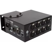
| 1 | DIP switches | to select the operating mode |
| 2 | DMX input | 8P8C (RJ45) input from external DMX controller |
| 3 | DMX output | 8P8C (RJ45) output to next LEDC09 device in daisy chain connection |
| 4 | DMX input | 3-pin XLR input from external DMX controller |
| 5 | DMX output | 3-pin XLR output to next LEDC09 device in daisy chain connection |
| 6 | terminals | |
| V- | to 12-24 VDC power supply (-) | |
| V+ | to 12-24 VDC power supply (+) | |
| COM | to LED strip, power | |
| CH1 | to LED strip, red (channel 1) | |
| CH2 | to LED strip, green (channel 2) | |
| CH3 | to LED strip, blue (channel 3) | |
| CH4 | to LED strip, white (channel 4) | |
Caution: Use either 8P8C connectors or 3-pin XLR connectors. Do not use both.
LEDC09
5. Test Mode
In test mode, you can set a static colour, or use changing colours at different speeds.
Static Colour
To set a static colour:
- Set DIP switch 10 to ON.
- Set DIP switches 8 and 9 to OFF.
- Select the desired static colour by setting the corresponding DIP switch (1-7) to on. If all DIP switches are off, all LED lights are out. If more than one DIP switch is set to on, the DIP switch with the highest value prevails:
| Colour | DIP switch | ||||||||
| 1 | 2 | 3 | 4 | 5 | 6 | 7 | 8 | 9 | |
| Red | 1 | 0 | 0 | 0 | 0 | 0 | 0 | 0 | 0 |
| Green | x | 1 | 0 | 0 | 0 | 0 | 0 | 0 | 0 |
| Blue | x | x | 1 | 0 | 0 | 0 | 0 | 0 | 0 |
| Yellow | x | x | x | 1 | 0 | 0 | 0 | 0 | 0 |
| Purple | x | x | x | x | 1 | 0 | 0 | 0 | 0 |
| Cyan | x | x | x | x | x | 1 | 0 | 0 | 0 |
| White | x | x | x | x | x | x | 1 | 0 | 0 |
0 = off; 1 = on; x = can be either on or off.
Changing Colours
To use changing colours:
- Set DIP switch 10 to ON.
-
Choose the desired dynamic mode:
-
For switching colours, set DIP switch 8 to on and DIP switch 9 to off.
-
For fading colours, set DIP switch 9 to on (DIP switch 8 can be either on or off).
-
Set the speed of the colour change by setting the corresponding DIP switch (1-7) to on. All DIP switches off = slowest; DIP switch 7 on = fastest. If more than one DIP switch is set to on, the DIP switch with the highest value prevails.
LEDC09
Some examples:
| Mode | DIP switch | ||||||||
| 1 | 2 | 3 | 4 | 5 | 6 | 7 | 8 | 9 | |
| Switching colours at medium speed | x | x | x | 1 | 0 | 0 | 0 | 1 | 0 |
| Fading colours at maximum speed | x | x | x | x | x | x | 1 | x | 1 |
0 = off; 1 = on; x = can be either on or off.
6. DMX Mode
To set the device to work with a DMX controller:
- Set DIP switch 10 to OFF.
- Connect the external DMX controller to the DMX input.
Caution: Use either 8P8C connectors or 3-pin XLR connectors. Do not use both.
- Use DIP switches 1-9 to specify the DMX address:
| Address | DIP switches |
| 5 | 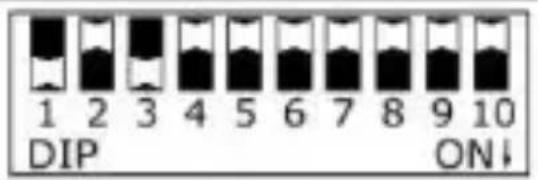 |
| 19 | 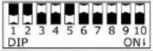 |
| 40 | 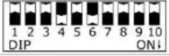 |
| Switch | Represents |
| 1 | 1 |
| 2 | 2 |
| 3 | 4 |
| 4 | 8 |
| 5 | 16 |
| 6 | 32 |
| 7 | 64 |
| 8 | 128 |
| 9 | 256 |
Set more than one DIP switch on and add their corresponding values to obtain the desired DMX address. For example: if only DIP switch 8 is on, the DMX address is 128. To obtain DMX address 19, set DIP switches 1, 2, and 5 to on (1 + 2 + 16 = 19).
7. Technical Specifications
| DMX channels | 4 |
| power supply | 12-24 VDC (not incl.) |
V. 03 - 08/08/2017 6 ©Velleman nv
LEDC09
| power output | 12 V | < 192 W |
| 24 V | < 384 W | |
| output current | 4 x 4 A | |
| input signal | DMX512 | |
| greyscale levels | 256 (8 bits) | |
| PWM frequency | ± 2600 Hz | |
| weight | 310 g | |
| dimensions | 165 x 68 x 40 mm | |
Use this device with original accessories only. Velleman nv cannot be held responsible in the event of damage or injury resulting from (incorrect) use of this device. For more info concerning this product and the latest version of this manual, please visit our website www.hqpower.eu. The information in this manual is subject to change without prior notice.
© COPYRIGHT NOTICE – The copyright to this manual is owned by Velleman nv. All worldwide rights reserved. No part of this manual may be copied, reproduced, translated or reduced to any electronic medium or otherwise without the prior written consent of the copyright holder.
GEBRUIKERSHANDLEIDING
1. Inleiding
0 = position OFF ; 1 = position ON ; x = position ON ou OFF.
0 = position OFF ; 1 = position ON ; x = position ON ou OFF.
LEDC09
6. Mode de pilotage DMX
natural_image
Symbol of a trash bin with crossed lines and a circular element, no text or numbers present.Velleman® Service and Quality Warranty
Since its foundation in 1972, Velleman® acquired extensive experience in the electronics world and currently distributes its products in over 85 countries.
All our products fulfil strict quality requirements and legal stipulations in the EU. In order to ensure the quality, our products regularly go through an extra quality check, both by an internal quality department and by specialized external organisations. If, all precautionary measures notwithstanding, problems should occur, please make appeal to our warranty (see guarantee conditions).
General Warranty Conditions Concerning Consumer Products (for EU):
- All consumer products are subject to a 24-month warranty on production flaws and defective material as from the original date of purchase.
- Velleman® can decide to replace an article with an equivalent article, or to refund the retail value totally or partially when the complaint is valid and a free repair or replacement of the article is impossible, or if the expenses are out of proportion.
You will be delivered a replacing article or a refund at the value of 100% of the purchase price in case of a flaw occurred in the first year after the date of purchase and delivery, or a replacing article at 50% of the purchase price or a refund at the value of 50% of the retail value in case of a flaw occurred in the second year after the date of purchase and delivery.
- Not covered by warranty:
- all direct or indirect damage caused after delivery to the article (e.g. by oxidation, shocks, falls, dust, dirt, humidity...), and by the article, as well as its contents (e.g. data loss), compensation for loss of profits; - consumable goods, parts or accessories that are subject to an aging process during normal use, such as batteries (rechargeable, non-rechargeable, built-in or replaceable), lamps, rubber parts, drive belts... (unlimited list);
- flaws resulting from fire, water damage, lightning, accident, natural disaster, etc....;
- flaws caused deliberately, negligently or resulting from improper handling, negligent maintenance, abusive use or use contrary to the manufacturer's instructions;
- damage caused by a commercial, professional or collective use of the article (the warranty validity will be reduced to six (6) months when the article is used professionally);
- damage resulting from an inappropriate packing and shipping of the article;
- all damage caused by modification, repair or alteration performed by a third party without written permission by Velleman®.
- Articles to be repaired must be delivered to your Velleman® dealer, solidly packed (preferably in the original packaging), and be completed with the original receipt of purchase and a clear flaw description.
- Hint: In order to save on cost and time, please reread the manual and check if the flaw is caused by obvious causes prior to presenting the article for repair. Note that returning a non-defective article can also involve handling costs.
• Repairs occurring after warranty expiration are subject to shipping costs.
- The above conditions are without prejudice to all commercial warranties.
The above enumeration is subject to modification according to the article (see article's manual).