
Par Batten - Effect machine HQ Power - Free user manual and instructions
Find the device manual for free Par Batten HQ Power in PDF.


| Product Type | Effect machine (fog/smoke machine) |
| Brand | HQ Power |
| Model | Par Batten |
| Dimensions (L × W × H) | 300 × 200 × 200 mm |
| Weight | 3 kg |
| Power Supply | 230 V ~ 50 Hz |
| Power Consumption | 500 W |
| Main Functions | Produces fog or smoke for stage effects, continuous or burst emissions |
| Tank Capacity | 1 L |
| Fluid Consumption | Approx. 100 ml/min |
| Heating Time | Approx. 3 minutes |
| Operating Temperature | 5 °C to 40 °C |
| Maintenance and Cleaning | Clean the tank with distilled water after use; check the nozzles; descale periodically |
| Safety | Use in a well-ventilated area; do not block vents; do not aim the jet at people or hot objects; disconnect before maintenance |
| Spare Parts and Repairability | Tank, fuse, heating element, pump (depending on model) |
| General Information | Professional indoor use; compatible with water-based fluids; supplied with power cable and manual |
Frequently Asked Questions - Par Batten HQ Power
User questions about Par Batten HQ Power
0 question about this device. Answer the ones you know or ask your own.
Ask a new question about this device
Download the instructions for your Effect machine in PDF format for free! Find your manual Par Batten - HQ Power and take your electronic device back in hand. On this page are published all the documents necessary for the use of your device. Par Batten by HQ Power.
USER MANUAL Par Batten HQ Power
LED PAR MINI RAMPA SCENICZNA - 16 X 3W

USER MANUAL 4
GE BRUIKERSHAND LEIDING 9
NOTICE D'EMPLOI 15
MANUAL DEL USUARIO 20


*: not inc. – niet meegelev. – non incl. – no incl. – nicht mitgeliefert – nie zał.


1 = GND
2 = SIG (-)
3 = SIG (+)
How to turn the controller line from 3-pins into 5-pins (plug and socket).
To all residents of the European Union
Important environmental information about this product

This symbol on the device or the package indicates that disposal of the device after its lifecycle could harm the environment. Do not dispose of the unit (or batteries) as unsorted municipal waste; it should be taken to a specialized company for recycling. This device should be returned to your distributor or to a local recycling service. Respect the local environmental rules.

If in doubt, contact your local waste disposal authorities.
Thank you for choosing HQPower™! Please read the manual thoroughly before bringing this device into service. If the device was damaged in transit, don't install or use it and contact your dealer.
2. Safe ty Instructions
 | Be very careful during the installation: touching live wires can cause life-threatening electroshocks. |
 | Always disconnect mains power when device not in use or when servicing or maintenance activities are performed. Handle the power cord by the plug only. |
  | Indoor use only. Keep this device away form rain, moisture, splashing and dripping liquids. |
 | Keep this device away from children and unauthorized users. |
 | Caution: device heats up during use. |
 | Do not stare directly at the light source, as this may cause• epilep tic seizure in sensitive people• temp orarily loss of sight (flash blindness)• perm anent (irreversible) eye damage. |
 | There are no user-serviceable parts inside the device. Refer to an authorized dealer for service and/or spare parts. |
- This device falls under protection class I. It is therefore essential that the device be earthed. Have a qualified person carry out the electric connection.
• Make sure that the available voltage does not exceed the voltage stated in the specifications of this manual. - Do not crimp the power cord and protect it against damage. Have an authorised dealer replace it if necessary.
- Use an appropriate safety cable to fix the device (e.g. VDLSC7 or VDLSC8).
- Install the VDPLDJBAR6 at a minimal distance of 0.5 m from flammable and explosive objects or substances.
- Respect a minimum distance of 1m between the device's light output and any illuminated surface.
3. Gen eral Guidelines
Refer to the Velleman® Service and Quality Warranty on the last pages of this manual.
 | Keep this device away from dust and extreme temperatures. |
 | Protect this device from shocks and abuse. Avoid brute force when operating the device. |
- Familiarise yourself with the functions of the device before actually using it. Do not allow operation by unqualified people. Any damage that may occur will most probably be due to unprofessional use of the device.
- All modifications of the device are forbidden for safety reasons. Damage caused by user modifications to the device is not covered by the warranty.
- Only use the device for its intended purpose. All other uses may lead to short circuits, burns, electroshocks, lamp explosion, crash, etc. Using the device in an unauthorised way will void the warranty.
- Damage caused by disregard of certain guidelines in this manual is not covered by the warranty and the dealer will not accept responsibility for any ensuing defects or problems.
• A qualified technician should install and service this device. - Do not switch the device on immediately after it has been exposed to changes in temperature. Protect the device against damage by leaving it switched off until it has reached room temperature.
- This device is designed for professional use on stage, in discos, theatres, etc. The VDPLDJBAR6 should only be used indoors with an alternating current of 230 VAC/50 Hz.
• Lighting effects are not designed for permanent operation: regular operation breaks will prolong their lives. - Keep this manual for future reference.
4. Features
• ultra-light weight: special for DJ and mobile use
- movable spots, per spot there are 4 tri-colour LEDs for a smooth colour mixing
- preprogrammed modes, with presets for colours and RGB programs
• auto mode speed adjustable, and built-in microphone for sound activation
- easy control via included foot pedal, with black-out function.
5. Overview
Refer to the illustrations on pages 2 and 3 of this manual.
| A | connector for LED spot (4x) | J | DIP switch |
| B | earth terminal | K | mounting points |
| C | power socket + fuse | L | horizontal fixing knob |
| D | tripod securing knob | M | vertical fixing knob (2 per spot) |
| E | DMX input | N | LEDs (4 per spot) |
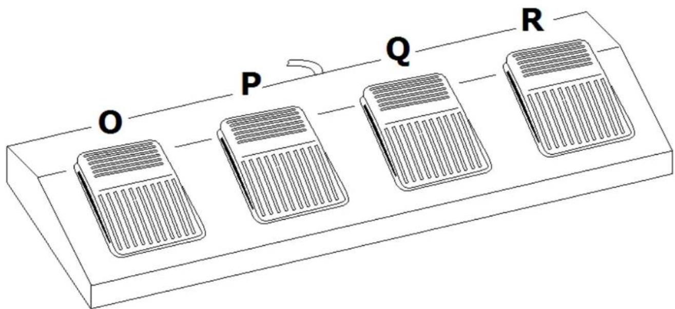
| F | DMX output | O | program selection pedal |
| G | microphone | P | sound control pedal |
| H | microphone sensitivity control knob | Q | freeze pedal |
| I | connector for footswitch | R | blackout pedal |
6. Mounting instructions
6.1 Choosing a Mounting Location

The VDPLDJBAR6 batten has been designed for indoor environments at temperatures up to 40°C. For proper operation, the unit must be operated with an unobstructed air convection to its metal housing.
Do not:
- Operate the batten in environments with an ambient temperature higher than 40° C and a relative humidity higher than 75%.
- Operate the batten in a closed environment smaller than 10m3 unless forced air convection is provided.
6.2 Secure Mounting

Risk of injury. Overhead mounting requires extensive experience: calculating workload limits, determining the installation material to be used... Have the material and the device itself checked regularly. Do not attempt to install the device yourself if you lack these qualifications as improper installation may result in injuries.
The VDPLDJBAR6 batten is designed to be mounted either on a tripod (not incl.) or on a truss (not incl.) using 2 truss clamps (not incl.).
Tripod:
- Carefully follow the instructions that came with your tripod.
- Make sure that the diameter of the inserted tripod tube is not less than 25 mm as otherwise secure mounting cannot be guaranteed.
- Slide the VDPLDJBAR6 over the tripod and secure it tightly by turning the knob [D] clockwise.
Truss mounting:
• Have the batten installed by a qualified person, respecting EN 60598-2-17 and all other applicable norms.
- The carrying construction must be able to support 10 times the weight of the batten for 1 hour without deforming.
- Remove both bolts [K] from the batten and replace them by 2 truss clamps (not incl.).
Note: ALWAYS mount the batten with two clamps!
• The installation must always be secured with a secondary attachment e.g. a safety cable.
- Never stand directly below the batten when it is being mounted, removed or serviced. Have a qualified technician check the batten once a year and once before you bring it into service.
• Install the batten in a location with few passers-by that is inaccessible to unauthorised persons.
• Make sure there is no flammable material within a 0.5 m radius of the batten.
- The installation has to be approved by an expert before the device is taken into service.
4-way footswitch:
Connect the footswitch to the light fixture [I].
6.3 DMX-512 connection
Refer to the illustrations on page 3 of this manual.
- When applicable, connect an XLR cable to the female 3-pin XLR output of a controller (not incl.) and the other side to the male 3-pin XLR input [E] of the VDPLDJBAR6. Multiple VDPLDJBAR6s can be linked through serial linking. The linking cable should be a dual core, screened cable with XLR input and output connectors.
- A DMX terminator is recommended for installations where the DMX cable has to run a long distance or is in an electrically noisy environment (e.g. discos). The terminator prevents corruption of the digital control signal by electrical noise. The DMX terminator is simply an XLR plug with a 120Ω resistor between pins 2 and 3, which is then plugged into the XLR output socket [F] of the last device in the chain.
6.4 Connection to the AC Power Supply

The AC socket providing power to the VDPLDJBAR6 batten must be properly and separately earthed. Do not use any other AC cords than the one provided or any other AC cord not authorized by the manufacturer.
• Have a qualified electrician carry out the electric connection.
- Connect the batten to the mains with the power plug [C]. Make sure the used mains circuit is protected by a 30mA Residual Current Device (RCD). Do not connect it to a dimming pack.
- Replace a blown fuse only with an identical fuse (F2A/250V).
7. Operation
Refer to the illustrations on page 2 of this manual.
The VDPLDJBAR6 can operate in five modes: sound controlled, automatic mode, master/slave mode, DMX controlled mode or foot switch mode.
Sound controlled mode
- Set DIP switch 10 to the OFF-position to enable sound controlled mode.

- Set the microphone [G] sensitivity with the sensitivity knob [H].
Automatic mode
- Set DIP switch 9 to the ON-position and DIP switch 10 to the OFF-position to enable automatic mode.
- Set the program speed with switches 1 to 3.
Master/slave mode
- Connect multiple VDPLDJBAR6's as described in §6.
- Set the master VDPLDJBAR6 to sound controlled or automatic mode.
- Set DIP switch 1 and 10 on the slaves to ON to enable slave mode.
DMX controlled mode
- Set DIP switch 10 to the ON-position to enable DMX controlled mode.
- All DMX-controlled devices need a digital start address so that the correct device responds to the signals. This digital start address is the channel number from which the device starts to "listen" to the DMX controller. The same starting address can be used for a whole group of devices or an individual address can be set for every device.
- When all devices have the same address, all the units will "listen" to the control signal on one particular channel. In other words: changing the settings of one channel will affect all devices simultaneously. If you set individual addresses, each device will "listen" to a separate channel number. Changing the settings of one channel will only affect the device in question.
- In case of the 15-channel VDPLDJBAR6, you will have to set the start address df the first unit to 1 (CH1\~15), the second unit to 16 (1 + 15) (CH16\~30), the third to 31 (16 + 15) ((CH31\~45), and so on.
- Use the DIP switches t to set the appropriate DMX address.
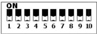
| switch | 1 | 2 | 3 | 4 | 5 | 6 | 7 | 8 | 9 |
| value | 1 | 2 | 4 | 8 | 16 | 32 | 64 | 128 | 256 |
• Refer to the table below for an overview of the control signals per channel.
| Channel | Function | DMX-512 value | Control Programs |
| CH1 | auto programs | 000 ~ 009 | off |
| 010 ~ 029 | Program 1 | ||
| 030 ~ 049 | Program 2 | ||
| 050 ~ 069 | Program 3 | ||
| 070 ~ 089 | Program 4 | ||
| 090 ~ 109 | Program 5 | ||
| 110 ~ 129 | Program 6 | ||
| 130 ~ 149 | Program 7 | ||
| 150 ~ 169 | Program 8 | ||
| 170 ~ 189 | Program 9 | ||
| 190 ~ 209 | Program 10 | ||
| 210 ~ 229 | Program 11 | ||
| 230 ~ 249 | Auto mode, internal programs | ||
| 250 ~ 255 | sound controlled mode | ||
| CH2 | master dimmer | no function when CH1 or CH3 active | |
| 000 ~ 000 | off | ||
| 001 ~ 255 | dimming 0 ~ 100% | ||
| CH3 str | obe | 000 ~ 000 | off |
| 001 ~ 255 | flash from slow to fast | ||
| CH4 sp | dt1 | 000 ~255 | red dimming from 0 ~ 100% |
| CH5 sp | dt1 | 000 ~255 | green dimming from 0 ~ 100% |
| CH6 sp | dt1 | 000 ~255 | blue dimming from 0 ~ 100% |
| CH7 sp | dt2 | 000 ~255 | red dimming from 0 ~ 100% |
| CH8 sp | dt2 | 000 ~255 | green dimming from 0 ~ 100% |
| CH9 sp | dt2 | 000 ~255 | blue dimming from 0 ~ 100% |
| CH10 sp | dt3 | 000 ~255 | red dimming from 0 ~ 100% |
| CH11 sp | dt3 | 000 ~255 | green dimming from 0 ~ 100% |
| CH12 sp | dt3 | 000 ~255 | blue dimming from 0 ~ 100% |
| CH13 sp | dt4 | 000 ~255 | red dimming from 0 ~ 100% |
| CH14 sp | dt4 | 000 ~255 | green dimming from 0 ~ 100% |
| CH15 sp | dt4 | 000 ~255 | blue dimming from 0 ~ 100% |
Foot controller
Note: the foot controller will only work when the VDPLDJBAR6 is set to automatic or sound controlled mode.
Unplug the power cord from the VDPLDJBAR6 and connect the foot controller to the foot controller jack [I]. Reconnect the power cord.
Foot controller functions:
| pedal 1 (O) | preset | Press to select a built-in program. | |
| 1x | white | ||
| 2x | red | ||
| 3x | green | ||
| 4x | blue | ||
| 5x | yellow | ||
| 6x | violet | ||
| 7x | cyan | ||
| 8x colour change every second, continuous loop | |||
| 9x colour fade every 3 seconds, continuous loop | |||
| pedal 2 (P) | sound controlled | press to enter sound controlled mode press pedal 1 to quit sound controlled mode | |
| pedal 3 (Q) | freeze hold chasing programs (8 & 9) | ||
| pedal 4 (R) | black out | Press at any time to switch off all LEDs. Press again to return to previous setting. Hold for strobe function. | |
8. Cleaning and Maintenance
- All screws should be tightened and free of corrosion.
- The housing, visible parts, mounting supports and the installation location (e.g. ceiling, suspension, trussing) should not be deformed, modified or tampered with e.g. do not drill extra holes in mounting supports, do not change the location of the connections.
- Moving mechanic parts must not show any signs of wear and tear.
- The electric power supply cables must not show any damage. Have a qualified technician maintain the device.
- Disconnect the device from the mains prior to maintenance activities.
- Wipe the device regularly with a moist, lint-free cloth. Do not use alcohol or solvents.
- There are no user-serviceable parts.
- Contact your dealer for spare parts if necessary.
9. Technical Specifications
| power supply 230VAC ~ 50Hz | |
| fuse | F2A/250V |
| power consumption 50W | |
| LED 16 x 3W tri-colour LEDs | |
| beam angle 15° | |
| dimensions 950 x 45 x 230mm | |
| total weight 6kg | |
Use this device with original accessories only. Velleman nv cannot be held responsible in the event of damage or injury resulted from (incorrect) use of this device.
For more info concerning this product and the latest version of this manual, please visit our website www.hqpower.eu.
The information in this manual is subject to change without prior notice.
© COPYRIGHT NOTICE
The copyright to this manual is owned by Velleman nv. All worldwide rights reserved.
No part of this manual may be copied, reproduced, translated or reduced to any electronic medium or otherwise without the prior written consent of the copyright holder.
GEBRUIKERSHANDLEIDING
1. Inlei ding
Velleman® Service and Quality Warranty
Since its foundation in 1972, Velleman® acquired extensive experience in the electronics world and currently distributes its products in over 85 countries.
All our products fulfil strict quality requirements and legal stipulations in the EU. In order to ensure the quality, our products regularly go through an extra quality check, both by an internal quality department and by specialized external organisations. If, all precautionary measures notwithstanding, problems should occur, please make appeal to our warranty (see guarantee conditions).
General Warranty Conditions Concerning Consumer Products (for EU):
- All consumer products are subject to a 24-month warranty on production flaws and defective material as from the original date of purchase.
- Velleman® can decide to replace an article with an equivalent article, or to refund the retail value totally or partially when the complaint is valid and a free repair or replacement of the article is impossible, or if the expenses are out of proportion.
You will be delivered a replacing article or a refund at the value of 100% of the purchase price in case of a flaw occurred in the first year after the date of purchase and delivery, or a replacing article at 50% of the purchase price or a refund at the value of 50% of the retail value in case of a flaw occurred in the second year after the date of purchase and delivery.
• Not covered by warranty:
- all direct or indirect damage caused after delivery to the article (e.g. by oxidation, shocks, falls, dust, dirt, humidity...), and by the article, as well as its contents (e.g. data loss), compensation for loss of profits;
- consumable goods, parts or accessories that are subject to an aging process during normal use, such as batteries (rechargeable, non-rechargeable, built-in or replaceable), lamps, rubber parts, drive belts... (unlimited list);
- flaws resulting from fire, water damage, lightning, accident, natural disaster, etc....;
- flaws caused deliberately, negligently or resulting from improper handling, negligent maintenance, abusive use or use contrary to the manufacturer's instructions;
- damage caused by a commercial, professional or collective use of the article (the warranty validity will be reduced to six (6) months when the article is used professionally);
- damage resulting from an inappropriate packing and shipping of the article:
- all damage caused by modification, repair or alteration performed by a third party without written permission by Velleman®.
- Articles to be repaired must be delivered to your Velleman® dealer, solidly packed (preferably in the original packaging), and be completed with the original receipt of purchase and a clear flaw description.
- Hint: In order to save on cost and time, please reread the manual and check if the flaw is caused by obvious causes prior to presenting the article for repair. Note that returning a non-defective article can also involve handling costs.
- Repairs occurring after warranty expiration are subject to shipping costs.
- The above conditions are without prejudice to all commercial warranties.
The above enumeration is subject to modification according to the article (see article's manual).
NL


- TO ALL RESIDENTS OF THE EUROPEAN UNION
- IMPORTANT ENVIRONMENTAL INFORMATION ABOUT THIS PRODUCT
- SAFE TY INSTRUCTIONS
- GEN ERAL GUIDELINES
- FEATURES
- OVERVIEW
- MOUNTING INSTRUCTIONS
- 6.1 CHOOSING A MOUNTING LOCATION
- DO NOT
- 6.2 SECURE MOUNTING
- TRIPOD
- TRUSS MOUNTING
- 4-WAY FOOTSWITCH
- 6.3 DMX-512 CONNECTION
- 6.4 CONNECTION TO THE AC POWER SUPPLY
- OPERATION
- SOUND CONTROLLED MODE
- AUTOMATIC MODE
- MASTER/SLAVE MODE
- DMX CONTROLLED MODE
- FOOT CONTROLLER
- CLEANING AND MAINTENANCE
- TECHNICAL SPECIFICATIONS
- © COPYRIGHT NOTICE
- GEBRUIKERSHANDLEIDING
- INLEI DING
- VELLEMAN® SERVICE AND QUALITY WARRANTY
- GENERAL WARRANTY CONDITIONS CONCERNING CONSUMER PRODUCTS (FOR EU)
- NOT COVERED BY WARRANTY
- NL
Brand : HQ Power
Model : Par Batten
Category : Effect machine