
EZChem - Dosing pump HAYWARD - Free user manual and instructions
Find the device manual for free EZChem HAYWARD in PDF.

| Product Type | Pool Dosing Pump |
| Brand | Hayward |
| Model | EZChem |
| Supply Voltage | 230 V~ 50 Hz |
| Power | 12 W (EZ-Chem only) / 18 W (with ORP kit) |
| Protection Rating | IP65 |
| Pump Flow Rate | 1.5 L/h |
| Maximum Pressure | 1.5 bar |
| Maximum Pool Volume | 90 m³ |
| pH Measurement Range | 6.0 to 9.0 pH |
| ORP Measurement Range | 0 to +1000 mV |
| Measurement Accuracy | ±0.1 pH ; ±10 mV |
| Main Functions | Automatic pH regulation and optionally liquid chlorine (via ORP kit) |
| Treatment Modes | pH only, Redox only, pH+Redox |
| Flow Detector | Yes, integrated (parameter must be set to On) |
| Probe Calibration | pH probe: buffer solutions pH 7 and pH 4 ; ORP probe: 465/468 mV solution |
| Corrective Product Type | Acid (pH-) or alkaline (pH+) |
| Materials | Plastic housing, PVC and PE tubes |
| Maintenance | Regular cleaning of probes, checking of hoses, use of original parts |
| Protection and Safety | IP65, automatic shutdown in case of fault, mandatory flow detector, use of original Hayward parts |
| Warranty | 2 years against manufacturing defects (excluding wear parts) |
Frequently Asked Questions - EZChem HAYWARD
User questions about EZChem HAYWARD
0 question about this device. Answer the ones you know or ask your own.
Ask a new question about this device
Download the instructions for your Dosing pump in PDF format for free! Find your manual EZChem - HAYWARD and take your electronic device back in hand. On this page are published all the documents necessary for the use of your device. EZChem by HAYWARD.
USER MANUAL EZChem HAYWARD
HAYWARD®

GUIDE DE L'UTILISATEUR
OWNER'S MANUAL
MANUAL DEL USUARIO
ANWENDERHANDBUCH
MANUALE D'USO

HAYWARD®

EZ-CHEM™
GUIDE DE L'UTILISATEUR
CONSERVEZ CE MANUEL POUR UNE CONSULTATION ULTÉRIEURE


HAYWARD®


EZ-CHEM™
OWNER'S MANUAL
SAVE THIS OWNER'S MANUAL


WARNING: Electrical Hazard. Failure to follow instructions can result in serious injury or death. FOR USE WITH RESIDENTIAL SWIMMING POOLS
WARNING – Carefully read the instructions that appear in this manual and on the device. Failure to comply with the instructions can cause injuries. This document must be given to every pool user who should keep it in a safe place.
⚠ WARNING – All electrical connections must be carried out by a qualified approved electrician in accordance with the standards currently in force in the country of installation.
| F NF | C 15-100 GB BS7671:1992 | |||
| D DIN VDE 0100-702 EW SIST HD 384-7-702.S2 | ||||
| A ÖVE 8001-4-702 H MSZ 2364-702:1994 / MSZ 10-533 1/1990 | ||||
| E | UNE 20460-7-702 1993, REBT ITC-BT-31 2002 | M | MSA HD 384-7-702.S2 | |
| IRL | IS HD 384-7-702 | PL | TS IEC 60364-7-702 | |
| I | CEI 64-8/7 | CZ | CSN 33 2000 7-702 | |
| LUX | 384-7.702 S2 | SK | STN 33 2000-7-702 | |
| NL | NEN 1010-7-702 | SLO | SIST HD 384-7-702.S2 | |
| P RSIUEE | TR TS | IEC 60364-7-702 | ||
⚠ WARNING – Check that the device is plugged into a 230 V socket, protected against short-circuits. The device must also be powered via an isolating transformer or a residual current device (RCD) with a nominal operating residual current not exceeding 30 mA.
WARNING – Check that the supply voltage required by the product corresponds to the voltage of the distribution network and that the power supply cables are suitable for the product power supply.
⚠ WARNING – To reduce the risk of electric shock, do not use an extension cable to connect the device to the mains. Use a wall socket.
WARNING – The device must not be used if the power cord is damaged. An electric shock could occur. A damaged power cord must be replaced by the after-sales service or similarly qualified persons to avoid danger.
⚠ WARNING – Unplug the device from the mains supply before any intervention.
⚠ WARNING – Ensure that children cannot play with the device. Keep your hands and any foreign object away from openings and moving parts.
WARNING – The device must not be used, cleaned or maintained by children over eight years of age or people with reduced physical, sensory or mental abilities or lack of experience or know-how until they have received appropriate instructions and without adequate supervision by a responsible adult to ensure safe handling and avoid any risk of danger. This device must remain out of the reach of children.
WARNING – Chemicals can cause internal and external burns. To avoid death, serious injury or damage to equipment: Wear personal protective equipment (gloves, goggles, mask, etc.) when servicing or maintaining this device. This device must be installed in an adequately ventilated place.
⚠ WARNING – Use only original Hayward parts. ONLY HAYWARD GENUINE REPLACEMENT PARTS
REGISTRATION
Thank you for choosing Hayward. This manual contains important information regarding the operation and maintenance of your product. Please retain it for reference.
TO REGISTER YOUR PRODUCT IN OUR DATABASE, GO TO:
www.hayward.fr/en/services/register-your-product

For Your Records
Record the following information for your convenience:
1) Purchase Date
2) Complete Name
3) Address
4) Zip code
5) Email Address
6) Part number ____ Serial number ____
7) Pool Dealer
8) Address
9) Zip code ____ Country ____
Note

GENERAL
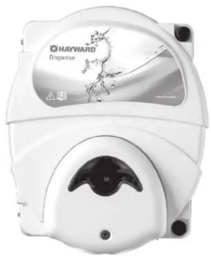
EZ-Chem is a device for regulating the pH of your pool.
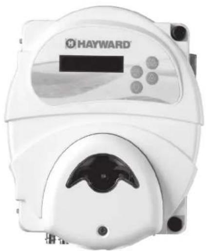
With the addition of an ORP kit (optional), it can also regulate both the pH and the liquid chlorine injection to provide you with a complete treatment.
EZ-Chem can treat pools up to 90 m 4 .
INSTALLATION
Disconnect the pool filter pump before starting the installation. The installation must be carried out in accordance with the standards currently in force in the country. The control box must be mounted a minimum horizontal distance of 3.5 m (or more, if required by local regulations) from the pool and within 1 m of a protected outlet.
Preparing the water in the pool
To prepare the pool water, its chemical composition must be balanced. Certain adjustments to the chemical balance of the pool can take several hours. It is therefore necessary to start the procedure well before switching the unit on.
Chemical water balance
The following table summarizes the concentrations recommended by Hayward. It is important to maintain these concentrations to prevent surface corrosion or deterioration and to derive full benefit from your pool. Control your water regularly. Your authorized Hayward dealer or pool suppliers will provide you with the chemicals you need, together with instructions on how to use them, to adjust the chemical balance of the water in your pool.
CHEMISTRY RECOMMENDED CONCENTRATIONS
| Free chlorine 1.0 to 3.0 ppm | |
| pH 7.2 to 7.6 | |
| Cyanuric acid (Stabiliser) | 20 to 30 ppm (preferably 25 ppm)Only add stabiliser if necessary |
| Total alkalinity 80 to 120 ppm | |
| Water hardness 200 to 300 ppm | |
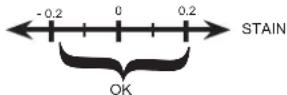
| Saturation index -0.2 to 0.2 (preferably 0) | |
Saturation index
The saturation index (Si) gives us information about the calcium content and alkalinity of the water; it is a water balance indicator. Your water is correctly balanced if the Si is 0 ± 0.2 . If the Si is below -0.2, the water is corrosive and the coating on the pool walls may be damaged. If the Si is above +0.2, stains may appear. Use the following table to determine the saturation index.
Use: Measure the pH of the pool water, the temperature, the water hardness and the total alkalinity. Use the table above to determine Ti, Ci and Ai in the above formula. If the Si is equal to 0.2 or more, stains may appear. If the Si is equal to -0.2 or less, corrosion or deterioration may occur.
CORROSION
USE ONLY HAYWARD GENUINE REPLACEMENT PARTS
Composition
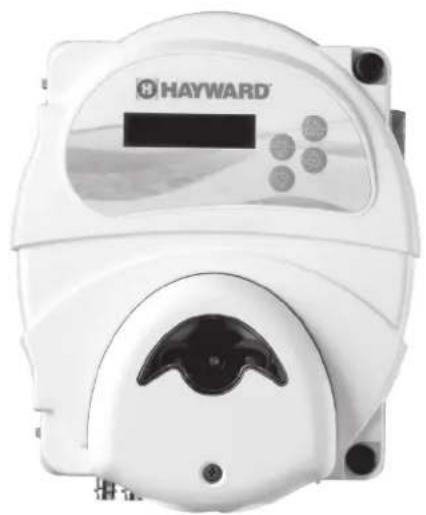
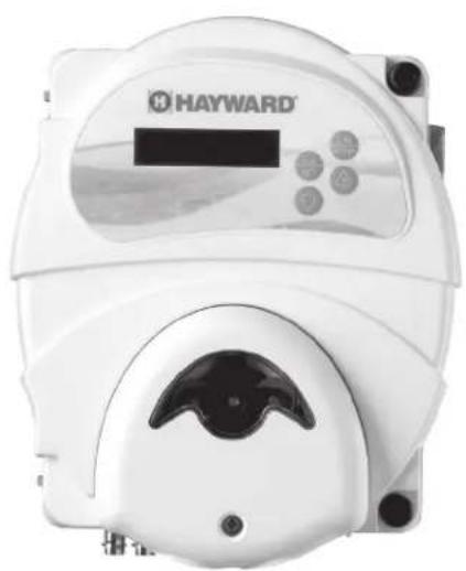
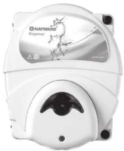
EZ-Chem
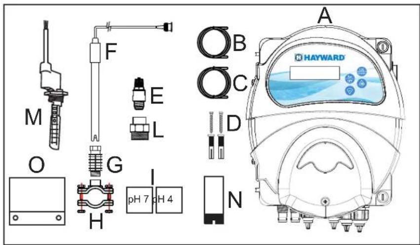
| A E Z-Chem housing |
| B T transparent PVC suction hose(4 m ∅4x6). |
| C Semi-rigid white PE injection tube(5 m ∅4x6). |
| D Installation kit(Check that screws are included) |
| E Injection valve (3/8" GAS). |
| F pH probe |
| G Probe holder |
| H 3 x saddle clamps for acid injection, flow switchand pH probe. |
| I pH 7 and pH 4 buffer solutions |
| L Injection valve reducers |
| M Flow switch |
| N Suction tube ballast |
| O Fixing plate |
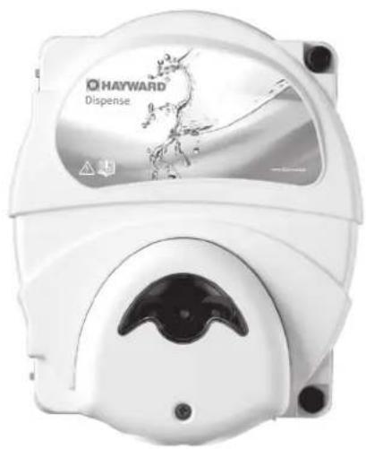
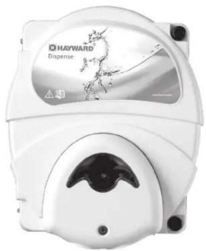
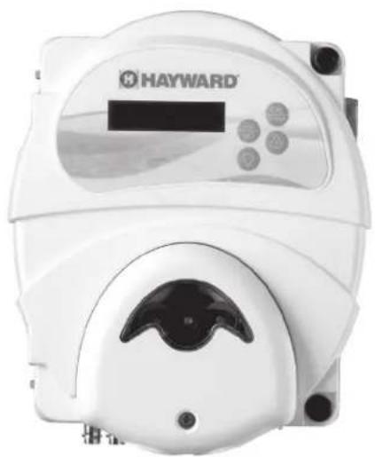
ORP kit for EZ-Chem (optional)
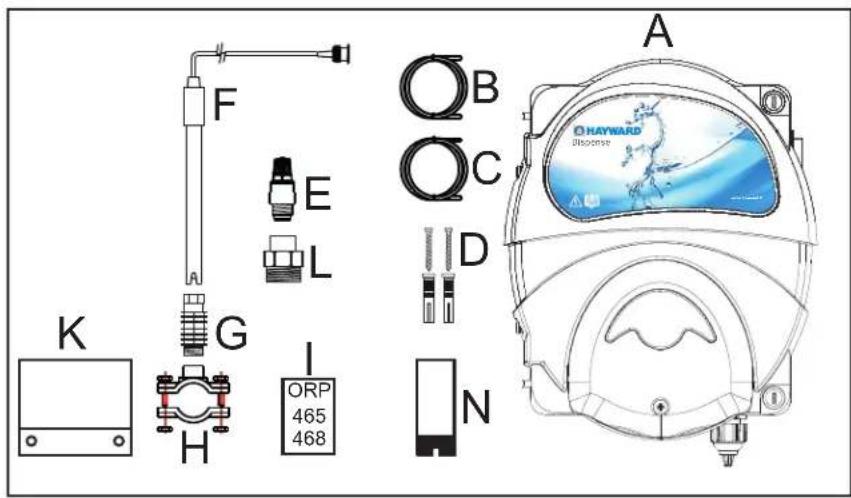
| A P | Peristaltic pump housing |
| B T | Transparent PVC suction hose(4 m ∅4x6). |
| C S | Semi-rigid white PE injection tube(5 m ∅4x6). |
| D | Installation kit(Check that screws are included) |
| E | Injection valve (3/8" GAS). |
| F | ORP Probe (Redox). |
| G | Probe holder |
| H 2 | x saddle clamps for acid injection and ORP probe. |
| I | ORP 465 / 468 calibration solution |
| K | Fixing plate. |
| L | Injection valve reducers |
| N | Suction tube ballast |

HAYWARD®
Installation
EZ-Chem only for pH regulation
![graph LR A["From pool"] --> B["Pump"] B --> C["Filter"] C --> D["pH probe"] D --> E["Heater"] E --> F["Flow switch"] F --> G["Acid injection"] G --> H["230V~50Hz"] H --> I["Back to pool"] I --> J["Pool"] style A fill:#f9f,stroke:#333 style J fill:#bbf,stroke:#333](/content/2026/04/615654/images/5109baec8d55d496974aa83f5cd36a8dc18d47dea0ec76b1996b7061223371d1.jpg)
EZ-Chem with an ORP kit for pH regulation and liquid chlorine injection.
![graph TD A["From pool"] --> B["Pump"] B --> C["Filter"] C --> D["ORP probe"] D --> E["pH probe"] E --> F["Heater"] F --> G["Chlorine injection"] G --> H["Back to pool"] H --> I["Chlorine"] I --> J["Acid injection"] J --> K["25 cm Flow switch"] K --> L["Chlorine"] L --> M["230V~50Hz"] M --> N["230V~5…](/content/2026/04/615654/images/f0c0bd727358b0c7e7c0a7053cfdc4826d1bdbbf1b5e6dd00ff35acb40effa6c.jpg)
USE ONLY HAYWARD GENUINE REPLACEMENT PARTS
WARNING – Chemicals can cause internal and external burns. To avoid death, serious injury and/or damage to equipment: Wear personal protective equipment (gloves, goggles, mask, etc.) when servicing or maintaining this device. It must be installed in an adequately ventilated room.
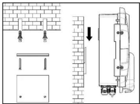
Mount the box (or both boxes if the ORP option is chosen) on the wall using the mounting kit supplied. The box must be installed in the equipment room (dry, temperate, ventilated). Caution, acid vapours and/or chlorine can cause irreversible damage to your device. Position the treatment product tanks accordingly.
The flow switch must be installed on the return pipe directly in line with and upstream of the treatment product injection point. Allow a 25 cm straight section before the flow switch. A hole should previously have been drilled in the pipe to allow the flow switch to pass through. Screw the flow switch (M) into the saddle clamp (H) taking care to seal with Teflon. Then install the clamp on the pipe. The flow switch must be installed in the direction of operation to ensure that it is tripped by the flow from the filter pump.
The probes must be installed on the filter outlet pipe to protect them from debris. A hole should previously have been drilled in the pipe to allow the probe to pass through. Fix the saddle clamp and install the probes in the clamp (H) with the probe (G) provided for this purpose. For the probes to operate, they must be vertical, with the cable upward. The probes must always remain wet. If the probes are allowed to dry, they will be permanently unusable (not covered by the warranty).
The treatment products must be injected last over the water return line, after any equipment (heater, etc.). A hole should previously have been drilled in the pipe to allow the treatment product to pass through. Install the saddle clamp (H) and screw the injection valve (E) into the saddle clamp using the adapter (L) provided. Seal with Teflon.
Connect the pH probe to the corresponding BNC connector.
Connect the ORP/RedoX probe to the corresponding BNC connector (if the ORP option is chosen).
Technical specifications
| Supply voltage | 230 V 50 Hz |
| EZ-Chem power 12 W | |
| EZ-Chem power + ORP kit 18 W | |
| Safety rating IP65 | |
| Pump delivery rate 1.5 l/h | |
| Maximum pressure 1.5 bar | |
| Max pool volume 90 m | 3 |
| pH measuring ranges 6.0 to 9.0 pH | |
| ORP measuring ranges 0 to +1000 mV | |
| Measuring accuracy | ± 0.1pH; ± 10mV |
USE ONLY HAYWARD GENUINE REPLACEMENT PARTS
Electrical connection:
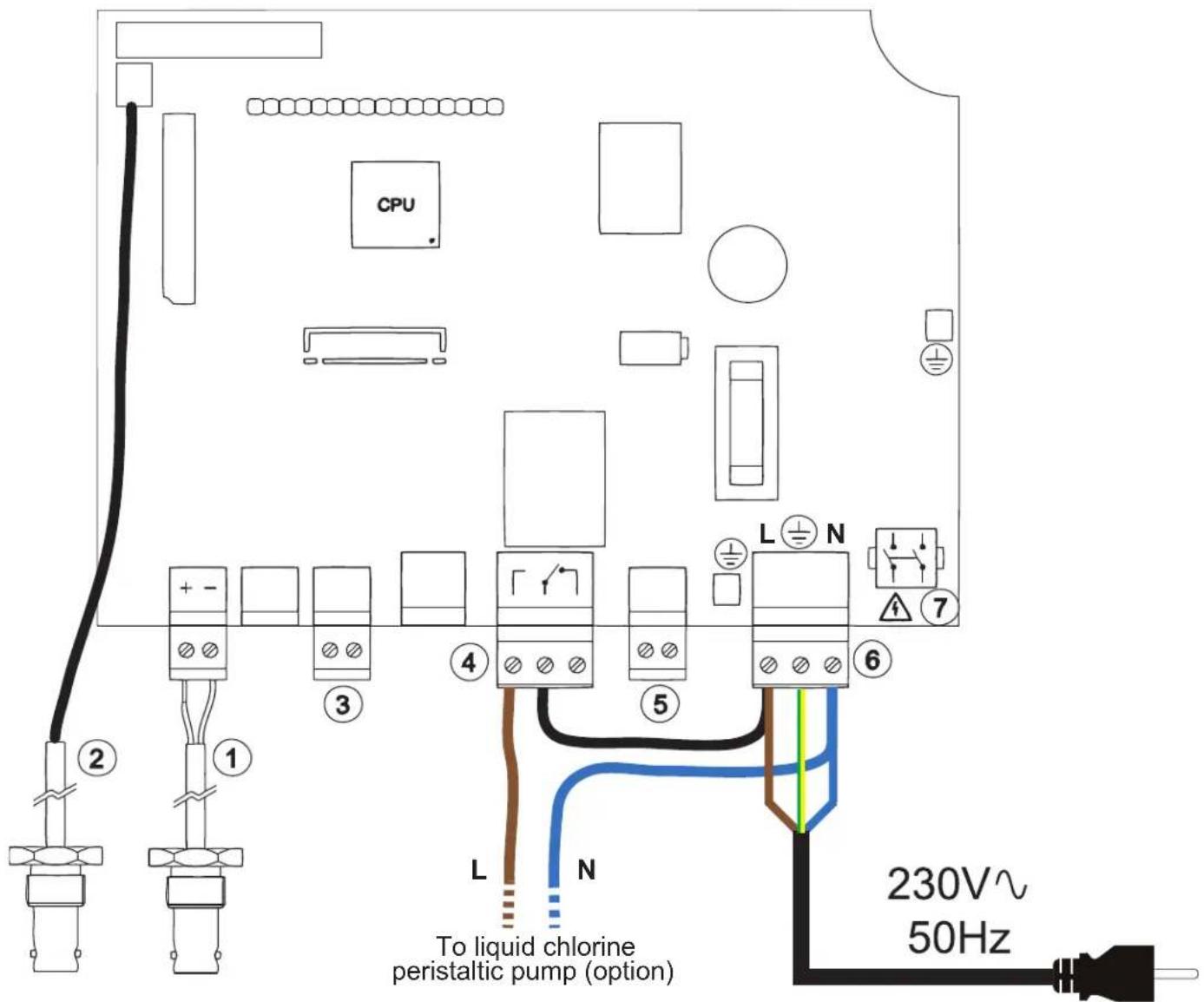
1 BNC connector for the pH probe
2 BNC connector for the ORP probe. Must only be connected if the ORP option is chosen (the probe is in the ORP kit).
3 Empty container sensor connection (optional).
4 Liquid chlorine peristaltic injection pump connection (only if the ORP option is chosen).
Connect the phase of terminal block 6 to the right-hand terminal of terminal block 4 to perform the bridging. Connect the neutral of the peristaltic pump to the neutral of terminal block 6 and connect the phase to the left-hand terminal of terminal block 4.
5 Flow switch connection. Only the blue and brown wires should be connected. Do not connect the black wire.
6 Main power supply connection (230 V\~ 50 Hz) in conformance with the local standard currently in force.
7 On/Off switch located on the right-hand side of the box.
CONFIGURATION
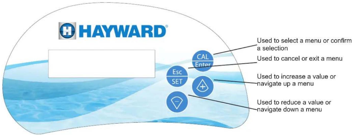
To configure the device, simultaneously press CAL and Esc for 5 seconds to display the following screen.
Program Configuration
Setting the language:
Program Configuration
press then
twice, then enter using .

Select the language using or and confirm with .

Setting the flow switch
Program Configuration
press then and enter using .

The parameter must be set to On. This parameter must never be set to OFF.
⚠ WARNING – injecting a treatment product when the filter pump is stopped can cause irreversible material damage and/or serious injuries.

HAYWARD®
Setting the treatment mode
This device is used to set:
- pH only: pH mode
- disinfectant only (ORP): Redox mode
- both pH and disinfectant (ORP): pH + Rx mode
The Redox or pH+Redox mode can only be activated with the ORP option sold separately. If you do not have the ORP option, please set the device to pH mode only.
To select the treatment mode:
Program Configuration
press then enter using

Select the treatment mode using or and confirm with .

Setting the pH set point
The device must be in pH mode or pH+Rx mode.
Program Configuration
press three times then enter using .

Set the pH set point using or and confirm with .

Ideally, the pH must be set to between 7.2 and 7.6.
Setting the ORP set point (only with the ORP option)
The device must be in pH+Rx mode.
Program Configuration
press five times then enter using .

Set the ORP set point using or and confirm with .

Ideally, ORP must be set to between 650 and 850.
Note: press twice only in "Redox" mode to set the ORP set point.
Priming the pumps
Hold down the button to prime the pH pump.
Hold down the button to prime the disinfectant (Chlorine) pump (only with the ORP option).

HAYWARD®
Calibrating the probes
pH probe
Use pH 7 and pH 4 buffer solutions (check expiry date).
Rinse your probe with tap water before immersing it in the pH 7 solution.
Hold down the button until the Pump Calibration pH Probe Cal. menu appears, then confirm with CAL Enter
The Press CAL B.Solut. 7pH menu appears.
Soak your probe in the pH 7 buffer solution and press CAL Enter
Wait until the countdown finishes (60 s) and the Quality 100% B.Solut. 7pH screen appears.
If the quality of the measurement is not 100%, repeat the calibration or replace the probe.
Rinse your probe with tap water before immersing it in the pH 4 solution.
Press the button.
The Press CAL B.Solut. 4pH menu appears.
Soak your probe in the pH 4 buffer solution and press

Wait until the countdown finishes (60 s) and the Quality 100% B. Solut. 4pH screen appears.
If the quality of the measurement is not 100%, repeat the calibration or replace the probe.
ORP Probe (Only with the ORP option)
Use the 465 / 468 mV calibration solution (check expiry date).
Rinse your probe with tap water before immersing it in the 465 / 468 mV solution.
Press when the calibration of the pH probe is finished.
When the following screen appears Pump Calibration Rx Probe Cal., confirm with CAL Enter
The 465 mV Press CAL menu appears.
Soak your probe in the 465 / 468 mV calibration solution and press

Wait until the countdown finishes (60 s) and the Quality 100% B.Solut. 465 mV screen appears, then confirm with CAL Enter
If the quality of the measurement is not 100%, repeat the calibration or replace the probe.
USE ONLY HAYWARD GENUINE REPLACEMENT PARTS

HAYWARD®
Full configuration overview - Review of the different parameters
On the Program Configuration screen, press
pH OFA Time Off
press to set the time after which the device will go into alarm mode if the pH set point has not been
reached (OFA). Select the time (or off by default) using or and confirm with .

Press to obtain pH Setpoint Type Acid and press to set the type of corrective product (acid (pH-) or alkaline (pH+)), then confirm with CAL Enter
Press to obtain pH Setpoint 7.4ph and press to set the pH set point using or and confirm with . Ideally, the pH must be set to between 7.2 and 7.6.
If you have connected the ORP kit (pH + Rx mode), press to obtain RX OFA Time Off and press to
set the time after which the device will go into alarm mode if the ORP (Redox) set point has not been reached (OFA). Select the time (or off by default) using or and confirm with . CAL Enter
Press to obtain RX Setpoint 750 mV and press to set the ORP (Redox) set point using or and confirm with . Ideally, ORP must be set to between 650 and 850.
Restoring the factory settings
Switch the device off and then on again by pressing the and buttons simultaneously.
The Init. Default Yes menu appears. Press to confirm.
The device is now in its factory configuration.
The factory configuration is as follows:
Treatment mode: pH only
Language: French
pH set point: 7.4
Type of corrective product: Acid
pH OFA alarm: Off
Flow switch: On
USE ONLY HAYWARD GENUINE REPLACEMENT PARTS
Troubleshooting guide
As most malfunctions are related to a poor water balance, we advise you to check it before handling the product (see chemical water balance).
| Alarm text Possible | causes Recommendation Action | ||
| "Flow" flashing Insufficient flow or no flow | Check the operation of the flow switch; if the contact is closed, "FLOW" remains steady, otherwise it flashes. | The fault automatically disappears once the problem is resolved | |
| Check that the filter pump is working correctly | |||
| Check the operating periods on the programming clock | |||
| Ensure that all the valves are open | |||
| Ensure that the water flows freely in the pipes | |||
| OFA Alr (pH) | Setting time too low | Increase the pH OFA alarm time (20 minutes to 240 minutes) | Press CAL Enter to remove the faultOr set the pH OFA alarm to OFF. |
| Acid container empty Replace the acid container | |||
| Rigid injection pipe blocked or pinched inspect the acid injection pipe, replace if necessary | |||
| Peristaltic pump problem | Check pump operation, press the (+) button to force it to operate, replace the pump if faulty | ||
| Inspect the membrane, replace if necessary | |||
| Difficulty reading the pH or unstable pH Check the water balance and recalibrate the pH probe | |||
| OFA STOP (pH) pH level not reached after 3 cycle times See recommendation for pH OFA Alarm | Press CAL Enter to remove the fault | ||
| OFA Alr (Rx) | Setting time too low | Increase the Redox OFA alarm time (20 minutes to 240 minutes) | Press CAL Enter to remove the faultOr set the Rx OFA alarm to OFF. |
| Chlorine container empty | Replace the liquid chlorine container | ||
| Rigid injection pipe blocked or pinched inspect the chlorine injection pipe, replace if necessary | |||
| Peristaltic pump problem | Check pump operation, press the (-) button to force it to operate, replace the pump if faulty | ||
| Inspect the membrane, replace if necessary | |||
| Difficulty to read Redox | Check the water balance and recalibrate the ORP probe | ||
| OFA STOP (Rx) | Redox level not reached after 3 cycle times | See Rx OFA Alr recommendation | Press CAL Enter to remove the fault |
| Parameter error | System error | Restore the default settings | N/A |
| Electronic problem, replace the device | |||
| Error 7 pH | pH probe calibration problem | Repeat the calibration | The fault automatically disappears once the problem is resolved |
| pH probe faulty | Check the pH probe connection with the BNC connector on the housing, inspect the probe and the cable | ||
| pH buffer solution out of date | Obtain a new solution | ||
| Error 4 pH | pH probe calibration problem | Repeat the calibration | |
| pH probe faulty | Check the pH probe connection with the BNC connector on the housing, inspect the probe and the cable | ||
| pH buffer solution out of date | Obtain a new solution | ||
| Error 465 mV | Rx probe calibration problem | Repeat the calibration | |
| Rx probe faulty | Check the connection of the Rx probe with the BNC connector on the housing, inspect the probe and the cable | ||
| Rx buffer solution out of date | Obtain a new solution | ||

HAYWARD®


EZ-CHEM™
MANUAL DEL USUARIO
CONSERVE ESTE MANUAL DE INSTRUCCIONES


HAYWARD®

EZ-CHEM™
ANWENDERHANDBUCH
BEWAHREN SIE DIESES HANDBUCH ZUM SPÄTEREN NACHSCHLAGEN AUF


www.hayward.fr/en/services/register-your-product

Für Ihre Unterlagen
VERWENDEN SIE NUR ORIGINAL-ERSATZTEILE VON HAYWARD
HAYWARD®


EZ-CHEM™
MANUALE D'USO
CONSERVARE IL PRESENTE MANUALE PER FUTURA CONSULTAZIONE


www.hayward.fr/en/services/register-your-product

Dati da conservare
All HAYWARD products are covered for manufacturing defects or material defects for a warranty period of 2 years as of date of purchases. Any warranty claim should be accompanied by evidence of purchase, indicating date of purchase. We would therefore advise you to keep your invoice.
The HAYWARD warranty is limited to repair or replacement, as chosen by HAYWARD, of the faulty products, provided that they have been subjected to normal use, in compliance with the guidelines given in their user guides, provided that the products have not been altered in any way, and provided that they have been used exclusively with HAYWARD parts and components. The warranty does not cover damage due to frost and to chemicals. Any other costs (transport, labour, etc.) are excluded from the warranty.
HAYWARD may not be held liable for any direct or indirect damage resulting from incorrect installation, incorrect connection, or incorrect operation of a product.
In order to claim on a warranty and in order to request repair or replacement of an article, please ask your dealer.
No equipment returned to our factory will be accepted without our prior written approval.
Wearing parts are not covered by the warranty.
GARANTÍA LIMITADA
BESCHRÄNKTE GARANTIE
- HAYWARD®
- WARNING: ELECTRICAL HAZARD. FAILURE TO FOLLOW INSTRUCTIONS CAN RESULT IN SERIOUS INJURY OR DEATH. FOR USE WITH RESIDENTIAL SWIMMING POOLS
- REGISTRATION
- TO REGISTER YOUR PRODUCT IN OUR DATABASE, GO TO
- FOR YOUR RECORDS
- NOTE
- GENERAL
- INSTALLATION
- PREPARING THE WATER IN THE POOL
- CHEMICAL WATER BALANCE
- SATURATION INDEX
- USE ONLY HAYWARD GENUINE REPLACEMENT PARTS
- COMPOSITION
- ELECTRICAL CONNECTION
- CONFIGURATION
- SETTING THE LANGUAGE
- SETTING THE FLOW SWITCH
- SETTING THE TREATMENT MODE
- SETTING THE PH SET POINT
- SETTING THE ORP SET POINT (ONLY WITH THE ORP OPTION)
- PRIMING THE PUMPS
- CALIBRATING THE PROBES
- PH PROBE
- ORP PROBE (ONLY WITH THE ORP OPTION)
- RESTORING THE FACTORY SETTINGS
- TROUBLESHOOTING GUIDE
- FÜR IHRE UNTERLAGEN
- VERWENDEN SIE NUR ORIGINAL-ERSATZTEILE VON HAYWARD
- EZ-CHEM™
- DATI DA CONSERVARE
- GARANTÍA LIMITADA
- BESCHRÄNKTE GARANTIE
Brand : HAYWARD
Model : EZChem
Category : Dosing pump