Swarm 4 FX - Effect machine Chauvet - Free user manual and instructions
Find the device manual for free Swarm 4 FX Chauvet in PDF.
User questions about Swarm 4 FX Chauvet
0 question about this device. Answer the ones you know or ask your own.
Ask a new question about this device
Download the instructions for your Effect machine in PDF format for free! Find your manual Swarm 4 FX - Chauvet and take your electronic device back in hand. On this page are published all the documents necessary for the use of your device. Swarm 4 FX by Chauvet.
USER MANUAL Swarm 4 FX Chauvet
natural_image
Technical line drawing of a mechanical enclosure or housing with mounting holes and internal components (no text or symbols)
LASER LIGHT
AVOID DIRECT EYE EXPOSURE
CLASS 3R LASER PRODUCT
CLASSIFIED PER EN/IEC 60825-1:2007
Complies with FDA performance standards
for laser products except for deviations
pursuant to Laser Notice No. 50, dated
June 24, 2007.
CHAUVET 3
TABLE OF CONTENTS
Warranty/Garantía/Garantie 5
Limited Warranty 5
Garantía Limitada 5
Garantie Limitée 5
1. Before You Begin....6
What Is Included....6
Unpacking Instructions....6
Claims 6
Manual Conventions....6
Symbols....6
Disclaimer....6
Safety Notes 7
Non-Interlocked Housing Warning 8
Laser Safety Notes 8
Laser Safety Label Reproduction....10
Laser Exposure Warning....11
Laser Emission Data 11
Laser Compliance Statement....11
2. Introduction......12
Overview....12
Dimensions....13
3. Setup 14
AC Power 14
Fuse Replacement 14
Power Linking....15
Power Linking Diagram 15
Mounting....16
Orientation....16
Rigging 16
Mounting Diagram....16
Proper Usage 17
4. Operation....18
Control Panel Operation....18
Menu Map....18
Configuration (DMX)....19
DMX Personality and Starting Address....19
Swarm 4 FX Zones for DMX Control....20
DMX Channel Assignments and Values 20
12CH 20
02CH 23
Configuration (Standalone) 24
Sound-Active Mode 24
Automatic Mode 24
Display Timeout....24
Test Mode 24
Factory Reset 24
IRC-6 (Infrared Remote Control) Operation 25
Master/Slave Mode 26
5. Technical Information....27
Product Maintenance 27
6. Technical Specifications ...... 28
Returns....29
Contact Us....30
2. Introduction......62
Vue d'Ensemble 62
Dimensions....63
3. Configuration 64
Alimentation CA....64
Configuration (DMX)....69
For Customers in the United States and Mexico: www.chauvetlighting.com/warranty-registration.
For Customers in the United Kingdom, Republic of Ireland, Belgium, the Netherlands, Luxembourg, France, and Germany: www.chauvetlighting.eu/warranty-registration.
Chauvet warrants that this product shall be free from defects in material and workmanship under normal use, for the period specified in, and subject to the exclusions and limitations set forth in the full limited warranty on our website. This warranty extends only to the original purchaser of the product and is not transferable. To exercise rights under this warranty, you must provide proof of purchase in the form of an original sales receipt from an authorized dealer that shows the product name and date of purchase. THERE ARE NO OTHER EXPRESS OR IMPLIED WARRANTIES. This warranty gives you specific legal rights. You may also have other rights that vary from state to state and country to country. This warranty is valid only in the United States, United Kingdom, Republic of Ireland, Belgium, the Netherlands, Luxembourg, France, Germany and Mexico. For warranty terms in other countries, please consult your local distributor.
Garantía Limitada
Unpacking Instructions
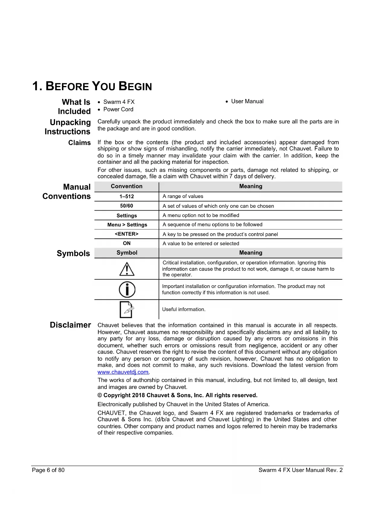
Carefully unpack the product immediately and check the box to make sure all the parts are in the package and are in good condition.
Claims
If the box or the contents (the product and included accessories) appear damaged from shipping or show signs of mishandling, notify the carrier immediately, not Chauvet. Failure to do so in a timely manner may invalidate your claim with the carrier. In addition, keep the container and all the packing material for inspection.
For other issues, such as missing components or parts, damage not related to shipping, or concealed damage, file a claim with Chauvet within 7 days of delivery.
| Manual Conventions | Convention | Meaning |
| 1-512 | A range of values | |
| 50/60 | A set of values of which only one can be chosen | |
| Settings | A menu option not to be modified | |
| Menu > Settings | A sequence of menu options to be followed | |
| A key to be pressed on the product's control panel | ||
| ON | A value to be entered or selected | |
| Symbols | Symbol | Meaning |
 | Critical installation, configuration, or operation information. Ignoring this information can cause the product to not work, damage it, or cause harm to the operator. | |
 | Important installation or configuration information. The product may not function correctly if this information is not used. | |
 | Useful information. |
Disclaimer
Chauvet believes that the information contained in this manual is accurate in all respects. However, Chauvet assumes no responsibility and specifically disclaims any and all liability to any party for any loss, damage or disruption caused by any errors or omissions in this document, whether such errors or omissions result from negligence, accident or any other cause. Chauvet reserves the right to revise the content of this document without any obligation to notify any person or company of such revision, however, Chauvet has no obligation to make, and does not commit to make, any such revisions. Download the latest version from www.chauvetdj.com.
The works of authorship contained in this manual, including, but not limited to, all design, text and images are owned by Chauvet.
© Copyright 2018 Chauvet & Sons, Inc. All rights reserved.
Electronically published by Chauvet in the United States of America.
CHAUVET, the Chauvet logo, and Swarm 4 FX are registered trademarks or trademarks of Chauvet & Sons Inc. (d/b/a Chauvet and Chauvet Lighting) in the United States and other countries. Other company and product names and logos referred to herein may be trademarks of their respective companies.
Safety Notes
The Safety Notes include important laser system safety information. Read and understand all instructions before powering on the laser for the first time. Knowing these safety instructions is crucial to avoiding laser eye injury and breaking the law. Keep this User Manual in a safe place for future reference.

STOP AND READ ALL LASER SAFETY DATA


- Lasers can be hazardous and have unique safety considerations. Permanent eye injury and blindness is possible if lasers are used incorrectly. Pay close attention to each safety REMARK and WARNING statement in this User Manual. Read all instructions carefully BEFORE operating this device.
- Always connect the product to a grounded circuit to avoid the risk of electrocution.
• Always disconnect the product from the power source before cleaning. - Avoid direct eye exposure to the light source while the product is on.
- Make sure the power cord is not crimped or damaged.
- Never disconnect the product from power by pulling or tugging on the cord.
- If mounting the product overhead, always secure to a fastening device using a safety cable.
- Make sure there are no flammable materials close to the product when operating.
- Do not touch the product's housing when operating because it may be very hot.

- This product is not intended for permanent installation.
- Always make sure that the voltage of the outlet to which you are connecting the product is within the range stated on the decal or rear panel of the product.
- The product is for indoor use only! (IP20) To prevent risk of fire or shock, do not expose the product to rain or moisture.
- Always install the product in a location with adequate ventilation, at least 20 in (50 cm) from adjacent surfaces.
- Be sure that no ventilation slots on the product's housing are blocked.
- Never connect the product to a dimmer.
- Always use the mounting bracket to carry the product.
- Do not switch the product on/off in short intervals. This will reduce the laser diode life.
- Do not shake this product. Avoid brute force when mounting or operating this product.
- ALWAYS use a safety cable when mounting the product overhead.
- The ambient operating temperature for the laser is 59 °F to 95 °F ( 15 °C to 35 °C ). Do not operate this product outside this range.
- In the event of a serious operating problem, stop using the product immediately.
- Never try to repair the product. Repairs carried out by unskilled people can lead to damage or malfunction. Contact the nearest authorized technical assistance center.

CAUTION! Use of controls, adjustments, or procedures other than THOSE specified IN THIS USER MANUAL may result in hazardous radiation exposure.

- Avoid direct eye contact with laser light. Never intentionally expose your eyes or others to direct laser light.
- This laser product can potentially cause instant eye injury or blindness if laser light directly strikes the eyes.
- It is illegal and dangerous to shine this laser into audience areas, where the audience or other personnel could get direct laser beams or bright reflections into their eyes.
- It is a U.S. federal offense to shine any laser at aircraft.
- Use of controls, adjustments, or procedures other than those specified in this User Manual may result in hazardous radiation exposure.
- To eliminate wear and improve its lifespan, during periods of non-use completely disconnect from power via breaker or by unplugging it.
- DO NOT attempt any repairs. Repairs and servicing must be carried out by a certified technician. Unauthorized modifications are forbidden for safety reasons!

Keep this User Manual for future consultation. If transferring ownership of the product to another user, be sure this document is kept with the laser.
Non-Interlocked Housing Warning
- This unit contains high power laser devices internally.
- Do not open the laser housing, due to potential exposure to unsafe levels of laser radiation.
- The laser power levels, accessible if the unit is opened, can cause instant blindness, skin burns, and fires.
Laser Safety Notes

STOP AND READ ALL THE LASER SAFETY NOTES BELOW

Laser light is different from any other light. Laser light can cause eye injury if the product is not set up and used properly. Laser light is a thousand times more concentrated than any other kind of light. This concentration can cause instant eye injuries by burning the retina (the light-sensitive portion at the back of the eye). The heat from a laser light cannot be felt, but it can still injure or blind product operators and the audience. Even very small amounts of laser light at long distances are are potentially hazardous.
DO NOT assume that exposure to an individual laser beam is safe, even a tiny beam split off from a larger beam. This laser product uses dozens of milliwatts of laser power—Class 3B levels internally—and splits them into multiple beams—Class 3R levels. The individual Class 3R level beams are potentially hazardous to the eyes.
DO NOT assume that a moving laser light is safe. Laser light is never without risk. Since eye injuries can occur instantly, it is critical to prevent the possibility of ANY direct eye exposure. According to laser safety regulations, it is not legal to aim Class 3R lasers into areas where people can be exposed, even if the laser is aimed below people's faces, such as at a dance floor.
- Do not operate the laser without first reading and understanding all the safety and technical data in this manual.
- ALWAYS set up and install all laser effects so that any laser light is at least 3 meters (9.8 feet) above the floor on which people are standing. See the Proper Usage section of this manual.
- After setup, and prior to public use, test the lasers to ensure they are functioning properly. Do not use the product if any defect is detected.
- DO NOT use laser if it is emitting only one or two beams, rather than dozens/hundreds, as this indicates damage to the diffraction grating optic, and allows emission of laser levels higher than Class 3R.
• DO NOT point lasers at people or animals.
• DO NOT look into the laser aperture or laser beams. - DO NOT point lasers into areas where people could be exposed to them.
- DO NOT point lasers at highly reflective surfaces such as windows, mirrors, and shiny metal. Even laser reflections can be hazardous.
- Never point a laser at aircraft; this is a U.S. federal offense.
- Never point un-terminated laser beams into the sky.
- Do not expose the output optic (aperture) to harsh cleaning chemicals.
- Do not use the laser if the housing is damaged, open, or if the optics appear damaged in any way.
- Never open the laser housing. The high laser power levels inside of the protective housing can start fires or burn skin, and will cause instant eye injury.
- Never leave this product running unattended.
- The operation of a Class 3R laser show is allowed only if the lasers are operated by a skilled and well-trained professional, who is familiar with the data included in this manual.
- The legal requirements for using laser entertainment products vary from country to country. The user is responsible for the legal requirements in the location/country of use.

CAUTION! Do not operate this device in ways not specified in this User Manual. Failure to follow the instructions will void the warranty, may damage the product, or injure the user or the audience.
CAUTION! This product cannot be discarded with household waste. Contact your local waste management service for electronic disposal regulations in your area.
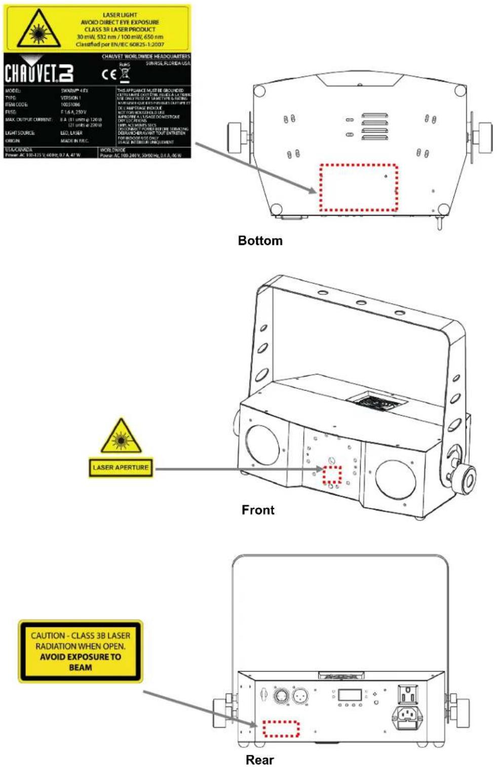
Laser Safety Label Reproduction
Laser Exposure
Warning

LASER LIGHT AVOID DIRECT EYE EXPOSURE
Further guidelines and safety programs for safe use of lasers can be found in the ANSI Z136.1 Standard “For Safe Use of Lasers”, available from the Laser Institute of America: www.laserinstitute.org. Many local governments, corporations, agencies, military, and others, require all lasers to be used under the guidelines of ANSI Z136.1. Laser Display guidance can be obtained via the International Laser Display Association: www.laserist.org.
Laser Emission Data
As measured under IEC measurement conditions for classification.
Laser Classification Class 3R
| Green Laser Medium | DPSS Nd:YVO4, 532 nm/30 mW |
| Red Laser Medium | LD GaAlAs, 650 nm/100 mW |
| Beam Diameter | <5 mm at aperture |
| Pulse Data | All pulses < 4 Hz (>0.25 sec) |
| Divergence (each beam) <2 mrad | |
| Divergence (total light) | <160 degrees |
| Laser Power of Each Beam from Aperture* | <5 mW |
Laser Compliance Statement
This laser product complies with EN/IEC 60825-1 Ed 2, 2007-03, and U.S. FDA/CDRH FLPPS via the terms of Laser Notice No. 50 dated June 24, 2007. This laser device is classified 3R. (Class 3R is the international equivalent of U.S. Class IIIa.) No maintenance is required to keep this product in compliance with laser performance standards.
2. INTRODUCTION
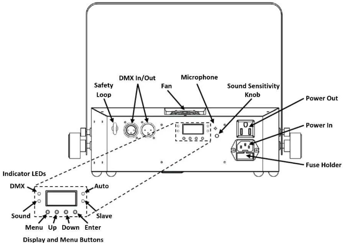
Overview
text_image
Safety Loop DMX In/Out Fan Microphone Sound Sensitivity Knob Power Out Power In Fuse Holder Indicator LEDs DMX Auto Sound Slave Menu Up Down Enter Display and Menu Buttons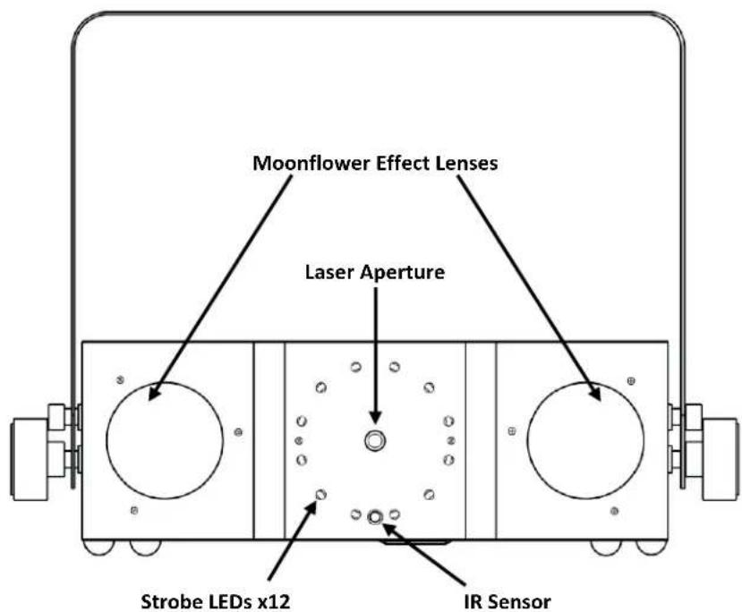
text_image
Moonflower Effect Lenses Laser Aperture Strobe LEDs x12 IR SensorDimensions
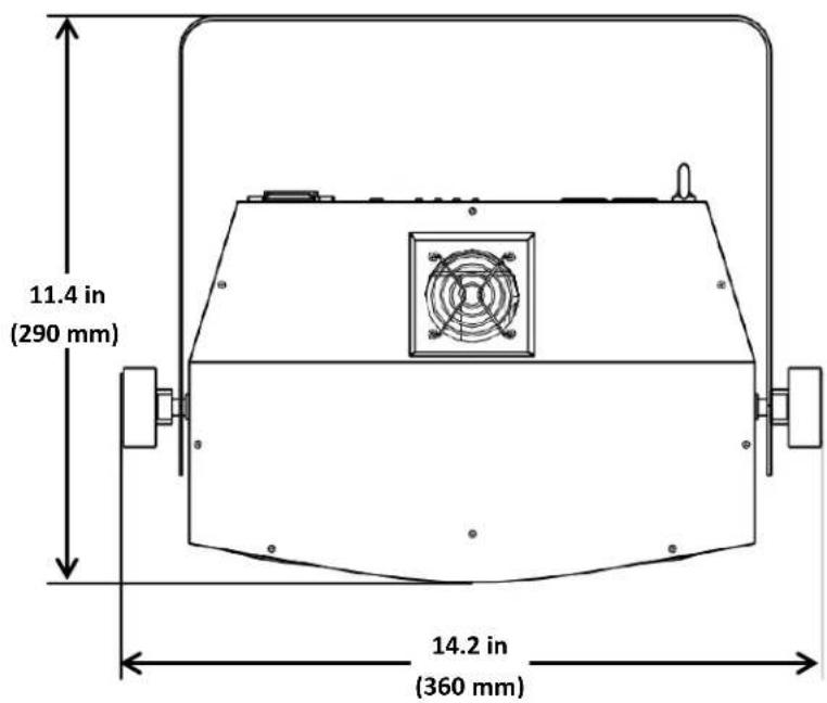
text_image
11.4 in (290 mm) 14.2 in (360 mm)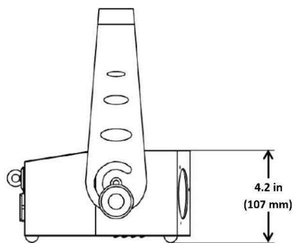
text_image
4.2 in (107 mm)3. SETUP
AC Power
The Swarm 4 FX has an internal auto-ranging power supply and it can work with an input voltage range of 100 to 240 VAC, 50/60 Hz.
To determine the product's power requirements (circuit breaker, power outlet, and wiring), use the current value listed on the label affixed to the product's back panel, or refer to 6. Technical Specifications in this manual. The listed current rating indicates the product's average current draw under normal conditions.

- Always connect the product to a protected circuit (circuit breaker or fuse). Make sure the product has an appropriate electrical ground to avoid the risk of electrocution or fire.
- To eliminate wear and improve its lifespan, during periods of non-use completely disconnect from power via breaker or by unplugging it.

Never connect the product to a rheostat (variable resistor) or dimmer circuit, even if the rheostat or dimmer channel serves only as a 0 to 100% switch.
Fuse Replacement
- Disconnect the product from power.
- Wedge the tip of a flat-head screwdriver into the slot of the fuse holder.
- Pry the fuse holder out of the housing.
- Remove the blown fuse from the holder.
- Replace with a fuse of the exact same type and rating.
- Insert the fuse holder back in place and reconnect power.

Disconnect the product from power before replacing the fuse.
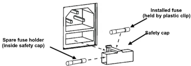
text_image
Spare fuse holder (inside safety cap) Installed fuse (held by plastic clip) Safety cap
The product does not ship with a spare fuse; however, the safety cap has room for a spare.

Always replace a blown fuse with a fuse of the same type and rating.
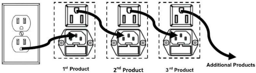
Power Linking
Power linking is when products are daisy chained together through the power in and power out plugs, allowing many products to be powered from one wall outlet.
Up to 11 Swarm 4 FX products can be power linked at 120 V, or up to 21 Swarm 4 FX products can be power linked at 230 V. The diagram below illustrates the power linking process.
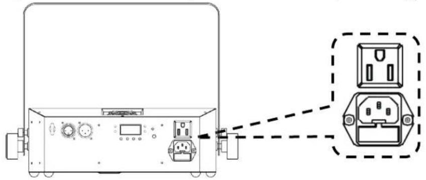
natural_image
Technical line drawing of a device rear panel with connected ports and connectors (no text or symbols)Power Linking Diagram
flowchart
graph LR
    A["1st Product"] --> B["2nd Product"]
    B --> C["3rd Product"]
    C --> D["Additional Products"]

Do not power link more than 11 Swarm 4 FX on 120 V. Do not power link more than 21 Swarm 4 FX on 230 V.

The power linking diagram above shows the North American version of the product only! Power linking connectors and requirements differ from country to country, and region to region. If using this product anywhere other than North America, consult with the local Chauvet distributor.
Mounting
Before mounting the product, read and follow the safety recommendations indicated in the Safety Notes. Use at least one mounting point per product. Make sure the mounting clamp (such as CLP-15 from Chauvet) is capable of supporting the weight of the product. For our Chauvet line of mounting clamps, go to www.chauvetlighting.com/cables-clamps-main.html.
Orientation
The Swarm 4 FX must be mounted in a position that includes planning for safe laser usage. In addition, make sure adequate ventilation is provided around the product.
Rigging
- Before deciding on a location for the product, always make sure there is easy access to the product for maintenance and programming.
- Make sure that the structure or surface onto which you are mounting the product can support the product's weight (see Technical Specifications).
- When mounting the product overhead, always use a safety cable (such as CH-05 from Chauvet). Mount the product securely to a rigging point, such as an elevated platform or a truss.
- When rigging the product onto a truss, you should use a mounting clamp of appropriate weight capacity. The bracket has a 13-mm hole, which is appropriate for this purpose.
- The bracket adjustment knobs allow for directional adjustment when aiming the product to the desired angle. Only loosen or tighten the bracket knobs manually. Using tools could damage the knobs.
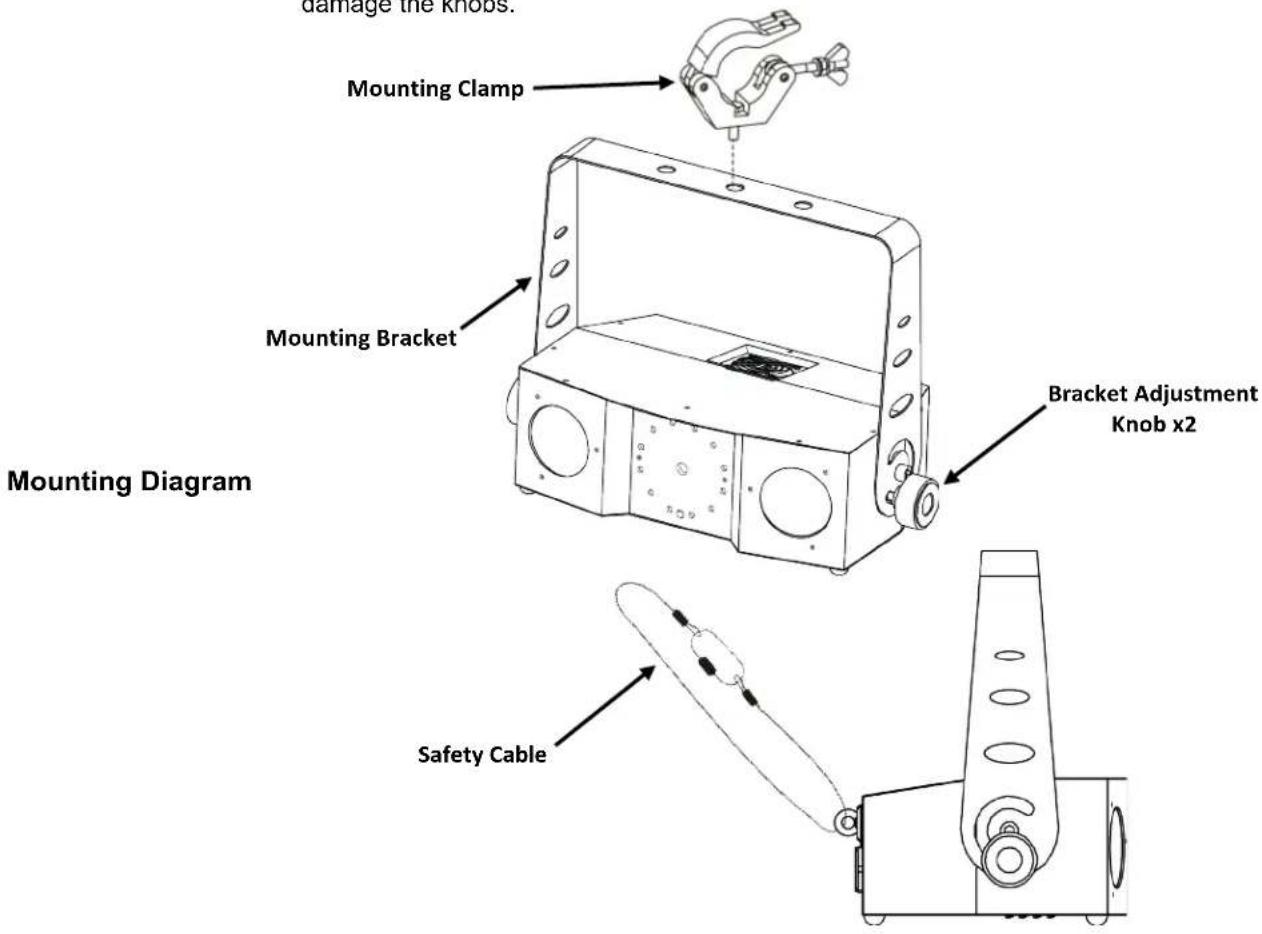
text_image
damage the knobs. Mounting Clamp Mounting Bracket Bracket Adjustment Knob x2 Mounting Diagram Safety CableProper Usage
This product is for overhead mounting only. For safety purposes, Chauvet recommends mounting lighting effect products on steady elevated platforms or sturdy overhead supports using suitable hanging clamps. In all cases, use safety cables. Obtain appropriate mounting hardware from your lighting vendor.
International laser safety regulations require that laser products must be operated in the fashion illustrated below, with a minimum of 3 meters (9.8 ft) of vertical separation between the floor and the lowest laser light. Additionally, 3 meters of horizontal separation is required between laser light and audience or other public spaces.
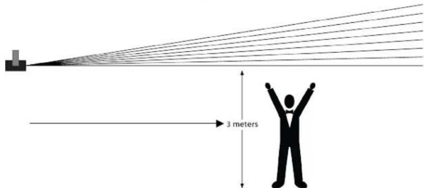
text_image
3 meters
CAUTION! Use of controls, adjustments, or procedures other than THOSE specified IN THIS USER MANUAL may result in hazardous radiation exposure.
4. OPERATION
This product is not designed for continual use. Make sure there are regular breaks during operation to maximize the life of your laser. Always disconnect the Swarm 4 FX from power when not in use.
Control Panel Operation
To access the control panel functions, use the four buttons located underneath the display. When the product is on, the LED monitor on the rear panel will show the current operating mode (Standalone or DMX). The product will retain the last saved settings when powered off.
| Button | Function |
| Selects an operation mode or backs out of the current menu option | |
| Scrolls up the list of options or selects a higher value | |
| Scrolls down the list of options or selects a lower value | |
| Activates a menu option or a selected value |
Menu Map
| Mode | Programming Steps | Description | |||
| Auto Mode Aut- | Aut0 | S.01-S.99 | Auto Mixed Effect | ||
| Aut1 | Moonflower - single color chase | ||||
| Aut2 | Moonflower - multi-color chase | ||||
| Aut3 | Laser + Strobe | ||||
| Aut4 | Moonflower + Strobe | ||||
| Aut5 | Moonflower (single color chase) + Laser | ||||
| Aut6 | Moonflower (multi-color chase) + Laser | ||||
| Aut7 | Alternating color Laser | ||||
| Aut8 | Laser | ||||
| Aut9 | Strobe | ||||
| Sound-Active Mode | Sou- | Sou0 | Sound Mixed Effect | ||
| Sou1 | Moonflower - single color chase | ||||
| Sou2 | Moonflower - multi-color chase | ||||
| Sou3 | Laser + Strobe | ||||
| Sou4 | Moonflower + Strobe | ||||
| Sou5 | Moonflower (single color chase) + Laser | ||||
| Sou6 | Moonflower (multi-color chase) + Laser | ||||
| Sou7 | Alternating color Laser | ||||
| Sou8 | Laser | ||||
| Sou9 | Strobe | ||||
| Slave Mode | SLA | SLAV | Slave mode | ||
| DMX Addr | d001-d511 | 02CH | d001-d511 | Sets DMX address and personality | |
| 12CH | d001-d501 | ||||
| System Options SYS | LEdS | on | Turns LEDs on | ||
| oFF | Turns LEDs off | ||||
| tESt | Test mode | ||||
| rESt | Reset to factory defaults | ||||
Configuration (DMX)
Set the product in DMX mode to control with a DMX controller. The product uses 3-pin DMX cable.
- Connect the product to a suitable power outlet.
- Connect a DMX cable from the DMX output of the DMX controller to the DMX input socket on the product.
DMX Personality and Starting Address
When selecting a DMX starting address, always consider the number of DMX channels used by the fixture. If you choose a starting address that is too high, you could restrict the access to some of the product's channels.
The Swarm 4 FX uses up to 12 DMX channels in the 12-channel mode, 12CH, which means the highest recommended DMX address for that personality is 501.
The Swarm 4 FX uses 2 DMX channels in the 2-channel mode, 02CH, which means the highest recommended DMX address for that personality is 511.
If you are not familiar with the DMX protocol, download the DMX Primer from http://www.chauvetlighting.com/downloads/DMX_Primer_Rev6_WO.pdf.
To select the DMX personality and starting address, do the following:
- Press
- Press
and 02CH or 12CH will show in the display - Use
or to select the DMX personality. - Press
and d001-d511 (for 02CH) or d001-d502 (for 12CH) will show on the display. - Use
or to select the DMX personality. - Press
.

The display will continue to blink until the fixture receives a DMX signal.
Swarm 4 FX Zones for DMX Control
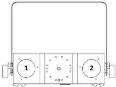
natural_image
Technical line drawing of a mechanical component with two circular ports labeled 1 and 2, no text or symbols present.DMX Channel Assignments and Values
| 12CH | Channel | Function | Value | Setting |
| 1 Moonflower 1 Control | 000 ⇔ 009 | No function | ||
| 010 ⇔ 019 | Red | |||
| 020 ⇔ 029 | Green | |||
| 030 ⇔ 039 | Blue | |||
| 040 ⇔ 049 | Amber | |||
| 050 ⇔ 059 | Red + green | |||
| 060 ⇔ 069 | Red + blue | |||
| 070 ⇔ 079 | Red + amber | |||
| 080 ⇔ 089 | Green + blue | |||
| 090 ⇔ 099 | Green + amber | |||
| 100 ⇔ 109 | Blue + amber | |||
| 110 ⇔ 119 | Red + green + blue | |||
| 120 ⇔ 129 | Red + green + amber | |||
| 130 ⇔ 139 | Red + blue + amber | |||
| 140 ⇔ 149 | Green + blue + amber | |||
| 150 ⇔ 159 | Red + green + blue + amber | |||
| 160 ⇔ 224 | Auto single color loop | |||
| 225 ⇔ 255 | Auto multicolor loop | |||
| 2 Moonflower 1 Strobe | 000 ⇔ 009 | No function | ||
| 010 ⇔ 254 | Strobe speed, slow to fast (when Ch. 1 is 010-159) | |||
| Program speed, slow to fast (when Ch. 1 is 160-255) | ||||
| 255 | Sound-Active | |||
| 3 Moonflower 1 Rotation | 000 ⇔ 004 | Stop | ||
| 005 ⇔ 127 | Rotate clockwise, slow to fast | |||
| 128 ⇔ 133 | Stop | |||
| 134 ⇔ 255 | Rotate counter-clockwise, slow to fast | |||
| 4 Moonflower 2 Control | 000 ⇔ 009 | No function | ||
| 010 ⇔ 019 | Red | |||
| 020 ⇔ 029 | Green | |||
| 030 ⇔ 039 | Blue | |||
| 040 ⇔ 049 | Amber | |||
| 050 ⇔ 059 | Red + green | |||
| 060 ⇔ 069 | Red + blue | |||
| 070 ⇔ 079 | Red + amber | |||
| 080 ⇔ 089 | Green + blue | |||
| 090 ⇔ 099 | Green + amber | |||
| 100 ⇔ 109 | Blue + amber | |||
| 110 ⇔ 119 | Red + green + blue | |||
| 120 ⇔ 129 | Red + green + amber | |||
| 130 ⇔ 139 | Red + blue + amber | |||
| 140 ⇔ 149 | Green + blue + amber | |||
| 150 ⇔ 159 | Red + green + blue + amber | |||
| 160 ⇔ 224 | Auto single color loop | |||
| 225 ⇔ 255 | Auto multicolor loop | |||
| 5 Moonflower 2 Strobe | 000 ⇔ 009 | No function | ||
| 010 ⇔ 254 | Strobe speed, slow to fast (when Ch. 1 is 010–159) | |||
| Program speed, slow to fast (when Ch. 1 is 160–255) | ||||
| 255 | Sound-Active | |||
| 6 Moonflower 2 Rotation | 000 ⇔ 004 | Stop | ||
| 005 ⇔ 127 | Rotate clockwise, slow to fast | |||
| 128 ⇔ 133 | Stop | |||
| 134 ⇔ 255 | Rotate counter-clockwise, slow to fast | |||
| 7 Lasers | 000 ⇔ 009 | No function | ||
| 010 ⇔ 049 | Red | |||
| 050 ⇔ 089 | Green | |||
| 090 ⇔ 129 | Red + green | |||
| 130 ⇔ 169 | Red on + green strobe | |||
| 170 ⇔ 209 | Green on + red strobe | |||
| 210 ⇔ 255 | Red + green (alternate strobe) | |||
| 8 Laser Strobe | 000 ⇔ 009 | No function | ||
| 010 ⇔ 254 | Strobe slow to fast | |||
| 255 | Sound-Active | |||
| 12CH Channel | Function | Value | Setting | |
| 9 Laser FX Rotation | 000 ⇔ 004 | Stop | ||
| 005 ⇔ 127 | Rotate clockwise, slow to fast | |||
| 128 ⇔ 133 | Stop | |||
| 134 ⇔ 255 | Rotate counter-clockwise, slow to fast | |||
| 10 Strobe Program | 000 ⇔ 009 | No function | ||
| 010 ⇔ 019 | Solid on | |||
| 020 ⇔ 029 | Program 1 | |||
| 030 ⇔ 039 | Program 2 | |||
| 040 ⇔ 049 | Program 3 | |||
| 050 ⇔ 059 | Program 4 | |||
| 060 ⇔ 069 | Program 5 | |||
| 070 ⇔ 079 | Program 6 | |||
| 080 ⇔ 089 | Program 7 | |||
| 090 ⇔ 099 | Program 8 | |||
| 100 ⇔ 109 | Program 9 | |||
| 110 ⇔ 119 | Program 10 | |||
| 120 ⇔ 129 | Program 11 | |||
| 130 ⇔ 139 | Program 12 | |||
| 140 ⇔ 149 | Program 13 | |||
| 150 ⇔ 159 | Program 14 | |||
| 160 ⇔ 169 | Program 15 | |||
| 170 ⇔ 179 | Program 16 | |||
| 180 ⇔ 189 | Program 17 | |||
| 190 ⇔ 199 | Program 18 | |||
| 200 ⇔ 255 | Program 19 | |||
| 11 | Strobe Program Speed | 000 ⇔ 255 | Program speed, slow to fast | |
| 12 Strobe Rate | 000 ⇔ 009 | No function | ||
| 010 ⇔ 254 | Strobe, slow to fast | |||
| 255 | Sound-Active | |||
| 02CH | Channel | Function | Value | Setting |
| 1 Program | 000 ⇔ 009 | No function | ||
| 010 ⇔ 021 | Auto program 0 | |||
| 022 ⇔ 033 | Auto program 1 | |||
| 034 ⇔ 045 | Auto program 2 | |||
| 046 ⇔ 057 | Auto program 3 | |||
| 058 ⇔ 069 | Auto program 4 | |||
| 070 ⇔ 081 | Auto program 5 | |||
| 082 ⇔ 093 | Auto program 6 | |||
| 094 ⇔ 105 | Auto program 7 | |||
| 106 ⇔ 117 | Auto program 8 | |||
| 118 ⇔ 127 | Auto program 9 | |||
| 128 ⇔ 140 | Sound-Active program 0 | |||
| 141 ⇔ 153 | Sound-Active program 1 | |||
| 154 ⇔ 166 | Sound-Active program 2 | |||
| 167 ⇔ 179 | Sound-Active program 3 | |||
| 180 ⇔ 192 | Sound-Active program 4 | |||
| 193 ⇔ 205 | Sound-Active program 5 | |||
| 206 ⇔ 218 | Sound-Active program 6 | |||
| 219 ⇔ 231 | Sound-Active program 7 | |||
| 232 ⇔ 244 | Sound-Active program 8 | |||
| 245 ⇔ 255 | Sound-Active program 9 | |||
| 2 | Program Speed | 000 ⇔ 255 | Slow to fast (when Ch. 1 is 010–127) |
Configuration (Standalone)
Set the product in one of the Standalone modes to control without a DMX controller.
Connect the product to a suitable power outlet.

Never connect a product that is operating in any Standalone mode (Static, Automatic, or Sound) to a DMX string connected to a DMX controller. Products in Standalone mode may transmit DMX signals that could interfere with the DMX signals from the controller.
Sound-Active Mode
To enable the Sound-Active mode, do the following:
- Press
- Press
and Sou0–Sou9 will show on the display. - Use
or to select the desired Sound-Active program. - Press
. - Turn the music on and adjust the sound sensitivity knob until the product starts responding to the beat of the music.

The product will only respond to low frequencies of music (bass and drums).
The product will blackout when in Sound-Active mode after 3 seconds of silence or noise below the sensitivity setting.
Automatic Mode
To enable the Automatic mode, follow the instructions below:
- Press
- Press
and Aut0–Aut9 will show on the display. - Use
or to select the desired Auto program. - Press
and S.01–S.99 will show on the display. - Use
or to adjust the program speed. - Press
.
Display Timeout
To enable or disable the Display Timeout, do the following:
- Press
- Press
and LEdS, tEST, or rEST will show on the display. - Use
or to select LEdS. - Press
and on or oFF will show on the display. - Use
or to select the Display Timeout to be on or oFF. - Press
.
Test Mode
To run the Swarm 4 FX in Test mode, follow the instructions below:
- Press
- Press
and LEdS, tEST, or rEST will show on the display. - Use
or to select tEST. - Press
.
Factory Reset
To reset the Swarm 4 FX to factory defaults, do the following:
- Press
- Press
and LEDs, tEST, or rEST will show on the display. - Use
or to select rESt. - Press
.
IRC-6 (Infrared Remote Control) Operation
Note: Make sure to point the IRC-6 directly at the receiver on the product.
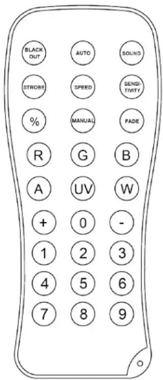
text_image
BLACK OUT AUTO SOUND STROSE SPEED GENSI- TIVITY % MANUAL FADE R G B A UV W + 0 - 1 2 3 4 5 6 7 8 9Automatic Mode
Automatic mode will enable you to run the automatic programs on the product.
To turn on Automatic mode:
- Press and hold
on the IRC-6. - Press any number between <0> and <9> to choose your auto program.
- Press < + > or < - > to either increase or decrease the speed of the program.
Sound-Active Mode
Sound-Active mode will enable the product to respond to the music.
To turn on Sound-Active mode:
- Press and hold
on the IRC-6. - Press any number between <0> and <9> to choose your auto program.
To adjust the strobe program and rate:
- Press
on the IRC-6. - Press <0> to strobe all, or any number between <1> and <9> to choose your auto program.
- Press < + > or < - > to increase or decrease, respectively, the strobe rate.
- Press
again to turn off the strobe.
Moonflower Color Modes
To set a specific color output for the moonflower effects:
- Press < > for red.
- Press
for green. - Press < B> for blue.
- Press < A> for amber.
- Press
for purple. - Press
for white.
Miscellaneous Operation
To black out the lights:
- Press
Note: The IRC-6 will not respond to any inputs when Black Out is activated. If the remote does not respond when a button is pressed, try pressing
Master/Slave Mode
The Master/Slave mode allows a single Swarm 4 FX product (the master) to control the actions of one or more Swarm 4 FX products (the slaves) without the need of a DMX controller. The master will be set to operate in either Automatic or Sound-Active mode, while the slaves will be set to operate in Slave mode. Once set and connected, the slave units will operate in unison with the master.
Configure the products as indicated below.
For every slave:
- Press
- Press
to put the fixture in Slave mode. SLAV will show on the display. - Repeat steps 1 and 2 for every slave.
- Connect the DMX output of the first slave unit to the DMX input of the next slave unit.
- Connect the DMX input of each subsequent slave unit to the DMX output of the previous slave unit.

Configure all the slave units before connecting the master to the DMX daisy chain. The display on the slaves will continue to blink until the slaves are receiving a DMX signal from the master.
For the master:
- Connect the DMX output of the master to the DMX input of the first slave unit.
- Set the master unit to operate in either Automatic or Sound-Active mode
• Make sure the master is the first unit in the DMX chain.
- Never connect a DMX controller to a DMX chain configured for Master/Slave operation because the controller may interfere with the signals from the master.
- Do not connect more than 31 slaves to the master.

5. TECHNICAL INFORMATION
Product Dust build-up reduces light output performance and can cause overheating. To maintain optimum performance, clean the product at least twice a month. However, usage and environmental conditions contribute to increasing the cleaning frequency.
To clean the product, follow the instructions below:
- Unplug the product from power.
- Wait until the product is at room temperature.
- Use a vacuum (or dry compressed air) and a soft brush to remove dust collected on the external surfaces and fan vents.
- Clean the glass panel (laser aperture) with a mild solution of glass cleaner or isopropyl alcohol.
- Apply the solution directly to a soft, lint-free cotton cloth or a lens cleaning tissue.
- Softly wipe any dirt or grime to the outside edges of the glass.
- Gently polish the glass surface until they are free of haze and lint.

Always dry the glass surfaces carefully after cleaning them.
6. TECHNICAL SPECIFICATIONS
| Dimensions and Weight | Length | Width | Height | Weight |
| 11.4 in (290 mm) | 14.2 in (360 mm) | 4.2 in (107 mm) | 5.4 lb (2.5 kg) | |
| Note: Dimensions in inches rounded to the nearest decimal digit. | ||||
| Power | Input Voltage | Range | Voltage Selection | |
| Switching (internal) | 100–240 VAC, 50/60 Hz | Auto-ranging | ||
| Parameter | 120 V, 60 Hz | 230 V, 50 Hz | ||
| Consumption | 47 W | 46 W | ||
| Operating current | 0.7 A | 0.4 A | ||
| Power linking current (units) | 8 A (11 units) | 8 A (21 units) | ||
| Fuse | F 1.6 A, 250 V | F 1.6 A, 250 V | ||
| Power I/O | US/Worldwide | UK/Europe | ||
| Power input connector | IEC | IEC | ||
| Power output connector | Edison | IEC | ||
| Power cord plug | Edison (US) | Local plug | ||
| Light Source | ||||
| Laser | Type | Power | Wavelength | |
| Laser (green) | 30 mW | 532 nm | ||
| Laser (red) | 100 mW | 650 nm | ||
| Moonflower | Type | Power | Lifespan | |
| LED | 13 W | 50,000 hours | ||
| Color | Quantity | Current | ||
| Quad-color RGBA | 2 | 4.4 A | ||
| Strobe | Type | Power | Lifespan | |
| LED | 1 W | 50,000 hours | ||
| Color | Quantity | Current | ||
| White | 12 | 300 mA | ||
| Photometrics | Parameter | |||
| Coverage angle (moonflower) | 54° | |||
| Coverage angle (strobe) | 69° | |||
| Strobe rate | 0–11 Hz | |||
| Thermal | Laser Maximum External Temp | Cooling System | ||
| 95 °F (35 °C) | Fan-Assisted Convection | |||
| DMX | I/O Connectors | Connector Type | Channel Range | |
| 3-pin XLR | Sockets | 2 or 12 | ||
| Ordering | Product Name | Item Code | UPC Code | |
| Swarm 4 FX | 10051086 | 781462214340 | ||

RETURNS
In case you need to get support or return a product:
• If you are located in the U.S., contact Chauvet World Headquarters.
• If you are located in the UK or Ireland, contact Chauvet Europe Ltd.
• If you are located in Benelux, contact Chauvet Europe BVBA.
• If you are located in France, contact Chauvet France.
• If you are located in Germany, contact Chauvet Germany.
• If you are located in Mexico, contact Chauvet Mexico.
- If you are located in any other country, DO NOT contact Chauvet. Instead, contact your local distributor. See www.chauvetdj.com for distributors outside the U.S., UK, Ireland, Benelux, France, Germany, or Mexico.

If you are located outside the U.S., UK, Ireland, Benelux, France, Germany, or Mexico, contact your distributor of record and follow their instructions on how to return CHAUVET® products to them. Visit our website www.chauvetdj.com for contact details.
Call the corresponding Chauvet Technical Support office and request a Return Merchandise Authorization (RMA) number before shipping the product. Be prepared to provide the model number, serial number, and a brief description of the cause for the return.
Send the merchandise prepaid, in its original box, and with its original packing and accessories. Chauvet will not issue call tags.
Clearly label the package with the RMA number. Chauvet will refuse any product returned without an RMA number.

Write the RMA number on a properly affixed label. DO NOT write the RMA number directly on the box.
Before sending the product, clearly write the following information on a piece of paper and place it inside the box:
- Your name
- Your address
- Your phone number
- RMA number
• A brief description of the problem
Be sure to pack the product properly. Any shipping damage resulting from inadequate packaging will be your responsibility. FedEx packing or double-boxing are recommended.

Chauvet reserves the right to use its own discretion to repair or replace returned product(s).
CONTACT Us
General Information Technical Support
Chauvet World Headquarters
Address: 5200 NW 108th Avenue
Sunrise, FL 33351
Voice: (954) 577-4455
Fax: (954) 929-5560
Toll free: (800) 762-1084
Voice: (844) 393-7575
Fax: (954) 756-8015
Email: chauvetcs@chauvetlighting.com
Website www.chauvetdj.com
Chauvet Europe Ltd
Address: Unit 1C
Brookhill Road Industrial Estate
Pinxton, Nottingham, UK
NG16 6NT
Voice: +44 (0)1773 511115
Fax: +44 (0)1773 511110
Email: UKtech@chauvetlighting.eu
Website: www.chauvetdj.eu
Chauvet Europe BVBA
(Entrance by Calle 2)
Zona Industrial Lerma
Lerma, Mexico C.P. 52000
Voice: +52 (728) 690-2010
Email: servicio@chauvet.com.mx
Website: www.chauvetdj.mx
Outside the U.S., U.K., Ireland, Benelux, France, Germany, or Mexico, contact the dealer of record. Follow the instructions to request support or to return a product. Visit our website for contact details
1. ANTES DE EMPEZAR
Que va
Incluido
- Swarm 4 FX
natural_image
Diagram of a device rear panel with connected outlets and control buttons, showing internal wiring (no text or labels)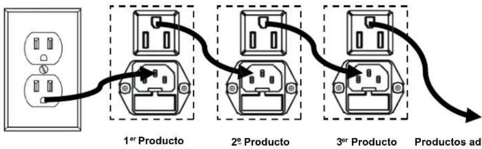
flowchart
graph LR
    A["1er Producto"] --> B["2o Producto"]
    B --> C["3er Producto"]
    C --> D["Productos adi"]

natural_image
Technical line drawing of a mechanical component with two circular ports labeled 1 and 2, no text or symbols present.Chauvet World Headquarters
Brookhill Road Industrial Estate
Pinxton, Nottingham, UK
NG16 6NT
Voz: +44 (0)1773 511115
UKtech@chauvetlighting.eu
Fax: +44 (0)1773 511110
Sitio web: www.chauvetdj.eu
Chauvet Europe BVBA
natural_image
Technical line drawing of a device rear panel with connected electrical socket (no text or symbols)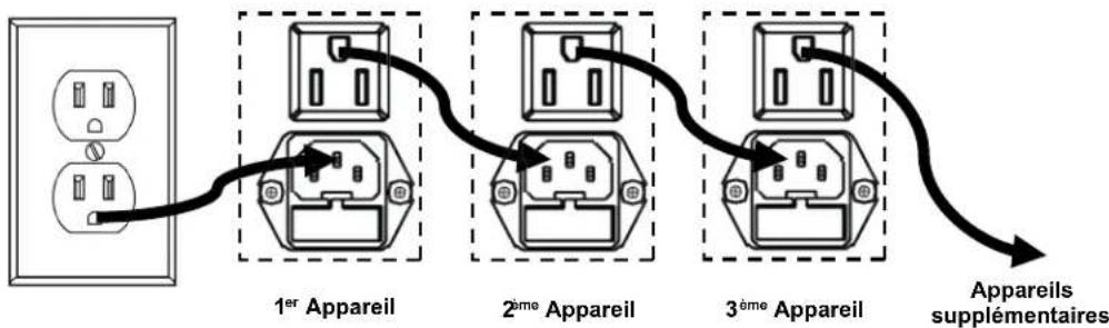
flowchart
graph LR
    A["Power outlet"] --> B["1er Apparel"]
    B --> C["2ème Apparel"]
    C --> D["3ème Apparel"]
    D --> E["Appareils supplémentaires"]