FMY 14 DRW XS - Warming drawers and cabinets FRANKE - Free user manual and instructions
Find the device manual for free FMY 14 DRW XS FRANKE in PDF.
| Product type | Warming drawer |
| Brand | Franke |
| Model | FMY 14 DRW XS |
| Temperature range | 40 °C to 75 °C (max) |
| Temperature settings | 40 °C (cups/glasses), 60 °C (plates), max 75 °C (dishes) |
| Maximum load capacity | 25 kg |
| Maximum weight of associated appliance | 60 kg |
| Controls | Temperature adjustment knob and illuminated on/off switch |
| Power indicator | Light on front panel |
| Drawer opening | Press center of front panel |
| Surface material | Metal and tempered glass at bottom |
| Cleaning metal surfaces | Soft microfibre cloth with water or glass cleaner |
| Cleaning tempered glass | Neutral detergent and warm water, then soft cloth |
| Cleaning precautions | Do not use abrasive products, steel wool, steam cleaner or chlorinated products |
| Installation | Must be fixed to the cabinet; can be installed under a compatible appliance (max 60 kg) |
| Power supply | Check voltage on rating plate |
| Safety | Turn off before removing dishes; do not leave children unattended |
| Maintenance | Disconnect before maintenance; wear protective gloves |
| First use | Preheat empty for 2 hours at maximum temperature |
| After-sales service | Contact an authorized Franke technical service center |
Frequently Asked Questions - FMY 14 DRW XS FRANKE
User questions about FMY 14 DRW XS FRANKE
0 question about this device. Answer the ones you know or ask your own.
Ask a new question about this device
Download the instructions for your Warming drawers and cabinets in PDF format for free! Find your manual FMY 14 DRW XS - FRANKE and take your electronic device back in hand. On this page are published all the documents necessary for the use of your device. FMY 14 DRW XS by FRANKE.
USER MANUAL FMY 14 DRW XS FRANKE
natural_image
Technical line drawing of a structural support frame with diagonal braces and a central rectangular component (no text or symbols)FMY 14 DRW
BEFORE USING THE WARMING DRAWER....4
INSTALLATION 4
OVERVIEW 5
OPERATION....5
TEMPERATURE SELECTION 5
WARMING TIMES......6
LOAD CAPACITY 6
CLEANING AND MAINTENANCE....6
TROUBLESHOOTING 7
SUPPORT 7
BEFORE USING THE WARMING DRAWER
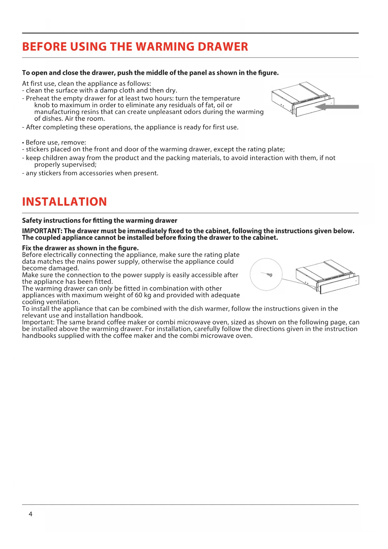
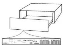
To open and close the drawer, push the middle of the panel as shown in the figure.
At first use, clean the appliance as follows:
- clean the surface with a damp cloth and then dry.
- Preheat the empty drawer for at least two hours: turn the temperature knob to maximum in order to eliminate any residuals of fat, oil or manufacturing resins that can create unpleasant odors during the warming of dishes. Air the room.
- After completing these operations, the appliance is ready for first use.
- Before use, remove:
- stickers placed on the front and door of the warming drawer, except the rating plate;
- keep children away from the product and the packing materials, to avoid interaction with them, if not properly supervised;
- any stickers from accessories when present.
INSTALLATION
natural_image
Pure technical line drawing of a mechanical component with no text or symbolsSafety instructions for fitting the warming drawer
IMPORTANT: The drawer must be immediately fixed to the cabinet, following the instructions given below. The coupled appliance cannot be installed before fixing the drawer to the cabinet.
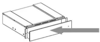
Fix the drawer as shown in the figure.
Before electrically connecting the appliance, make sure the rating plate data matches the mains power supply, otherwise the appliance could become damaged.
Make sure the connection to the power supply is easily accessible after the appliance has been fitted.
The warming drawer can only be fitted in combination with other appliances with maximum weight of 60 kg and provided with adequate cooling ventilation.
To install the appliance that can be combined with the dish warmer, follow the instructions given in the relevant use and installation handbook.
Important: The same brand coffee maker or combi microwave oven, sized as shown on the following page, can be installed above the warming drawer. For installation, carefully follow the directions given in the instruction handbooks supplied with the coffee maker and the combi microwave oven.
natural_image
Technical line drawing of a mechanical assembly with a magnified inset showing a pin detail (no text or symbols)OVERVIEW
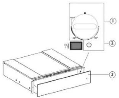
- Temperature knob
- Luminous ON-OFF switch
- ON-OFF Indicator
text_image
Technical diagram of a device with labeled components and a control panel showing max, min, and rotation directions.The control elements are the temperature knob and the luminous ON-OFF switch.
With the switch pressed (position 1), the drawer is on, whereas with the switch released (position 0), the drawer is off.
These elements are only visible when the drawer is open.
When the drawer is closed, a control light located on the front of the appliance indicates if the drawer is on.
OPERATION
- Place the dishes in the drawer
- Set a temperature
- Turn the appliance on; the switch lights up
- Close the drawer, guiding it carefully
- Turn the appliance off before removing the warmed dishes
TEMPERATURE SELECTION
The temperature control knob allows adjustments up to approx. 75^ C (max). Turn the temperature knob clockwise until the stop which indicates maximum, and then anticlockwise. Do not force it beyond the stop, otherwise the thermostat will become damaged.
| Temperature adjustment Instructions for use | ||
| 40°C cups, glasses | Cups and glasses warmed at this temperature help delay the cooling time of the beverage subsequently added. Use gloves to remove containers from the drawer. | |
| 60°C plates | Plates warmed at this temperature help delay the cooling time of food subsequently placed on them. Use gloves to remove containers from the drawer. | |
| MAX approx. 75°C | crockery | The thermostat is set to the maximum temperature. Use gloves to remove containers from the drawer. |
WARMING TIMES
The time required to warm dishes, glasses, etc. depends on various factors:
- Material and thickness of the dishes
- Load
- Arrangement of load
• Temperature setting
Therefore absolute indications cannot be given.
It is advisable to establish the optimum settings required, based on practical experience
LOAD CAPACITY
The load capacity depends on the height of the appliance and the size of the dishes. Remember that the drawer can take a maximum weight of 25 kg.
CLEANING AND MAINTENANCE
Make sure that the appliance has cooled down before carrying out any maintenance or cleaning. Do not use steam cleaners.
The appliance must be disconnected from the mains before carrying out any kind of maintenance work.
Wear protective gloves.
Do not use wire wool, abrasive scourers or abrasive/corrosive cleaning agents, as these could damage the surfaces of the appliance.
For metal surfaces, proceed as follows:
- Use a soft cloth (preferably microfiber) with water or a normal glass cleaning detergent.
- Do not use paper towels, which could leave traces of paper and streaks on the surface.
- Do not use abrasive or corrosive products, chlorine-based products or scouring pads.
- Do not use flammable steam cleaning devices.
- Do not leave acid or alkaline substances, such as vinegar, mustard, salt, sugar or lemon juice, on the surface.
For glass surfaces, proceed as follows:
- Use a neutral detergent and lukewarm water, then dry with a soft cloth.
- Do not leave acid or alkaline substances, such as vinegar, mustard, salt, sugar or lemon juice, on the surface.
Tempered glass drawer base
It is advisable to clean the bottom of the drawer after each use, making sure to let it cool. This will prevent the build-up of dirt and make cleaning easier.
- Use a clean cloth, paper towels and washing up liquid, or specific products for cleaning the tempered glass.
- Do not use abrasive products, bleach, oven cleaner spray or metallic scouring pads.
TROUBLESHOOTING
If the dishes are not warm enough, check that:
• the appliance is switched on
• the right temperature has been set
• ventilation openings are not covered by plates or large bowls
• the dishes were not heated long enough.
• the mains switch has not been turned off.
Different factors affect the warming time, for example:
- material and thickness of the dishes, the load and its arrangement, temperature setting.
- The optimum times for warming dishes vary, therefore it is advisable to do tests to establish them according to needs.
WWW.FRANKE.COM
© Franke Technology and Trademark Ltd, Switzerland
SUPPORT
In the event of any operation problems, contact a Franke Technical Service Centre.
Never use the services of unauthorized technicians.
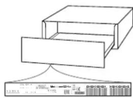
Specify:
- the type of fault
- the appliance model (art./Code)
- the serial number (S.N.)
When contacting our
Service Centre, please state the codes provided on your product's identification plate.
flowchart
graph TD
    A["Input Box 1"] --> C["Output Box 1"]
    B["Input Box 2"] --> C["Output Box 1"]
INHALT
natural_image
Pure technical line drawing of a mechanical component with no text or symbolsINSTALLATION
natural_image
Technical line drawing of a mechanical assembly with a magnified inset showing a pin detail (no text or symbols)ÜBERSICHT
text_image
Technical diagram of a device with labeled components and a control panel showing angular measurements.© Franke Technology and Trademark Ltd, Switzerland
SUPPORT
natural_image
Diagram of a mechanical component with an arrow indicating direction (no text or symbols present)natural_image
Technical line drawing of a mechanical assembly with a magnified inset showing a pin detail (no text or symbols)APERÇU
text_image
Technical diagram of a device with labeled components and a control panel showing max, min, and power connections.© Franke Technology and Trademark Ltd, Switzerland
ASSISTANCE
flowchart
graph TD
    A["Start"] --> B["Mood and Buy"]
    B --> C["Terminal Box"]
text_image
FR +SOMMARIO
PRIMA DI USARE IL CASSETTO RISCALDANTE....19
INSTALLAZIONE 19
natural_image
Diagram of a mechanical component with a directional arrow indicating motion (no text or symbols)INSTALLAZIONE
natural_image
Technical line drawing of a mechanical component with a magnified inset showing a pin detail (no text or symbols)text_image
Technical diagram showing a device with labeled components and a control panel with rotary dial indicators© Franke Technology and Trademark Ltd, Switzerland
ASSISTENZA
natural_image
Pure technical line drawing of a mechanical component with no text or symbolsINSTALACIÓN
natural_image
Technical line drawing of a mechanical assembly with a magnified inset showing a pin detail (no text or symbols)DESCRIPCIÓN GENERAL
text_image
Technical diagram of a device with labeled components and a control panel showing max, min, and rotation directions.© Franke Technology and Trademark Ltd, Switzerland
ASISTENCIA
natural_image
Pure technical line drawing of a mechanical component with no text or symbolsINSTALAÇÃO
natural_image
Technical line drawing of a mechanical component with a magnified inset showing a pin detail (no text or symbols)text_image
Technical diagram showing a device with labeled components and a control panel, including numbered parts ①, ②, and ③.© Franke Technology and Trademark Ltd, Switzerland
SUPORTE
natural_image
Diagram of a mechanical component with an arrow indicating direction (no text or symbols present)natural_image
Technical line drawing of a mechanical assembly with a magnified inset showing a pin (no text or symbols)WIDOK OGÓLNY
text_image
Technical diagram of a device with labeled components and a control panel showing max, min, and rotation directions.© Franke Technology and Trademark Ltd, Switzerland
WSPARCIE TECHNICZNE
natural_image
Diagram of a mechanical component with a directional arrow indicating movement (no text or symbols)natural_image
Technical line drawing of a mechanical assembly with a magnified inset showing a pin detail (no text or symbols)PŘEHLED
text_image
Technical diagram showing a device with labeled components and a control panel, including numbered parts ①, ②, and ③.© Franke Technology and Trademark Ltd, Switzerland
TECHNICKÁ PODPORA
natural_image
Pure technical line drawing of a mechanical component with no text or symbolsINŠTALÁCIA
natural_image
Technical line drawing of a mechanical assembly with a magnified inset showing a pin (no text or symbols)text_image
Technical diagram of a device with labeled components and a control panel showing max, min, and rotation directions.© Franke Technology and Trademark Ltd, Switzerland
TECHNICKÁ PODPORA
natural_image
Diagram of a mechanical component with a directional arrow indicating motion (no text or symbols)ΕΓΚΑΤΑΣΤΑΣΗ
natural_image
Technical line drawing of a mechanical component with a magnified inset showing a pin detail (no text or symbols)ΕΠΙΣΚΟΠΗΣΗ
text_image
Technical diagram showing a device with labeled components and a control panel with rotary dial indicators© Franke Technology and Trademark Ltd, Switzerland
ΥΠΟΣΤΗΡΙΞΗ
natural_image
Diagram of a mechanical component with an arrow indicating direction (no text or symbols present)natural_image
Technical line drawing of a mechanical assembly with a magnified inset showing a pin detail (no text or symbols)PREZENTARE GENERALĂ
text_image
Technical diagram of a device with labeled components and a control panel showing max, min, and rotation directions.© Franke Technology and Trademark Ltd, Switzerland
ASISTENTĂ
natural_image
Diagram of a mechanical component with a directional arrow indicating motion (no text or symbols)MONTAJ
natural_image
Technical line drawing of a mechanical component with a magnified inset showing a pin detail (no text or symbols)text_image
Technical diagram showing a device with labeled components and a control panel, including numbered parts ①, ②, and ③.© Franke Technology and Trademark Ltd, Switzerland
DESTEK
natural_image
Diagram of a mechanical component with an arrow indicating direction (no text or symbols present)УСТАНОВКА
natural_image
Technical line drawing of a mechanical assembly with a magnified inset showing a pin (no text or symbols)text_image
Technical diagram of a device with labeled components and a control panel showing max, min, and rotation directions.© Franke Technology and Trademark Ltd, Switzerland
ПОМОЩЬ
natural_image
Diagram of a mechanical component with a directional arrow indicating motion (no text or symbols)natural_image
Technical line drawing of a mechanical assembly with a circular inset showing a pin inserted into a housing (no text or symbols)text_image
Technical diagram of a device with labeled components and a control panel showing angular measurements.© Franke Technology and Trademark Ltd, Switzerland
ПІДТРИМКА
natural_image
Diagram of a mechanical component with an arrow indicating direction (no text or symbols present)natural_image
Technical line drawing of a mechanical assembly with a magnified inset showing a pin inserted into a housing (no text or symbols)text_image
Technical diagram of a device with labeled components and a control panel showing max, 60°, 40°, and 30° angles.© Franke Technology and Trademark Ltd, Switzerland
دعامة
flowchart
graph TD
    A["Start"] --> B["Process Step 1"]
    B --> C["End"]
natural_image
Diagram of a mechanical component with a directional arrow indicating motion (no text or symbols)natural_image
Technical line drawing of a mechanical component with a magnified inset showing a pin detail (no text or symbols)text_image
Technical diagram showing a device with labeled components and a control panel with rotary dial indicators© Franke Technology and Trademark Ltd, Switzerland