CrossGrip - Lamp Laserliner - Free user manual and instructions
Find the device manual for free CrossGrip Laserliner in PDF.
| Product type | Magnetic support for laser measuring instruments |
| Brand | Laserliner |
| Model | CrossGrip |
| Dimensions (L x H x D) | 70 x 180 x 200 mm |
| Weight | 562 g |
| Power supply | None (passive accessory) |
| Mounting thread | 1/4" |
| Number of magnets | 2 powerful |
| Wall mounting | Screw holes |
| Clamp fixing | Yes, with adjustment screw |
| Main applications | Horizontal and vertical fixing on dry construction profiles, fixing on magnetic surfaces |
| Compatibility | Laser measuring instruments with 1/4" thread |
| Maintenance | Clean with a slightly damp cloth, without abrasive or solvent |
| Storage | Dry and clean place |
| Safety | Risk of pinching, strong magnetic fields, keep 30 cm away from implants |
| Standards | Compliant with EU directives |
| Spare parts and repairability | No detachable parts, not user-repairable |
| Additional information | See www.laserliner.com for safety instructions |
Frequently Asked Questions - CrossGrip Laserliner
User questions about CrossGrip Laserliner
0 question about this device. Answer the ones you know or ask your own.
Ask a new question about this device
Download the instructions for your Lamp in PDF format for free! Find your manual CrossGrip - Laserliner and take your electronic device back in hand. On this page are published all the documents necessary for the use of your device. CrossGrip by Laserliner.
USER MANUAL CrossGrip Laserliner
natural_image
Black plastic mechanical device with mounting bracket and side slots (no visible text or symbols)
magnetic

Laserliner
!
text_image
Labeled diagram of a mechanical device with numbered parts for identification
natural_image
Three-panel diagram showing a device with a sensor array, one being processed, the other assembled, and the final assembled (no text or symbols present)natural_image
Close-up of a black and white mechanical component next to a circular logo with a U-shaped symbol (no text or labels visible)natural_image
Mechanical device with directional arrow indicating movement or force (no visible text or symbols)
natural_image
Close-up of a mechanical device with a control panel and mounted components (no visible text or symbols)
natural_image
Mechanical assembly diagram showing a mounted device with mounting brackets and a side-mounted bracket, no text or symbols present.Completely read through the operating instructions, the "Warranty and Additional Information" booklet as well as the latest information under the internet link at the end of these instructions. Follow the instructions they contain. This document must be kept in a safe place and passed on together with the device.
Function / Application
Magnetic clamping and wall bracket for versatile use
- For all laser measuring devices with 1/4" thread
- With the magnetic clamp and wall bracket the device can be used as a standalone unit, in a combination as well as in horizontal and vertical position.
- Ideal for mounting horizontally and vertically on drywall construction profiles.
text_image
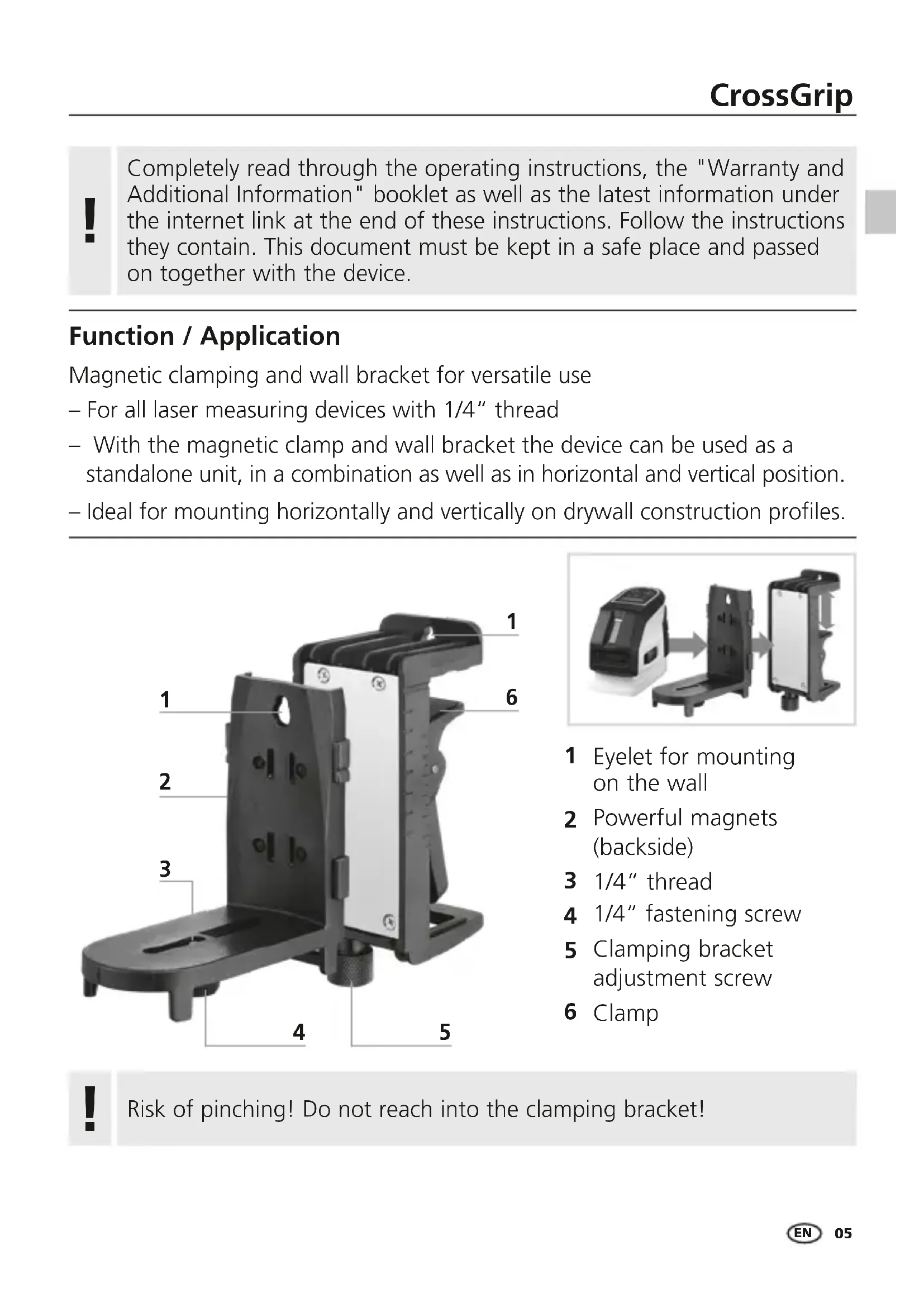
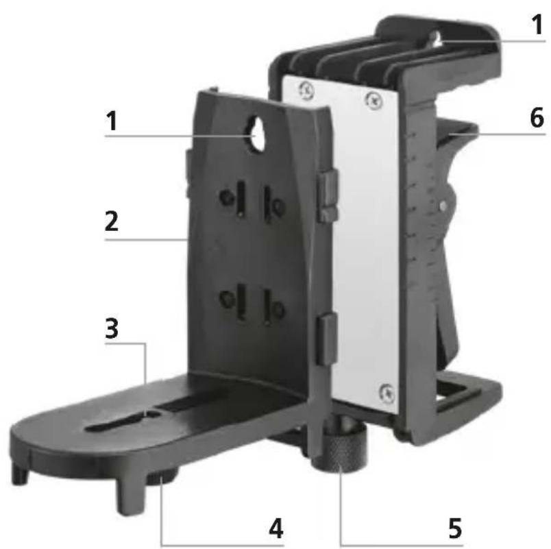
Technical diagram of a mechanical device with numbered parts labeled 1 through 6
natural_image
Three-step assembly diagram showing a device with a cover, part of a black plastic housing, and a final black-and-white component (no text or symbols visible)1 Eyelet for mounting on the wall
2 Powerful magnets (backside)
3 1/4" thread
4 1/4" fastening screw
5 Clamping bracket adjustment screw
6 Clamp
!
Risk of pinching! Do not reach into the clamping bracket!
Laserliner
1Mounting on a wall
The lugs (1) facilitate direct mounting on walls.
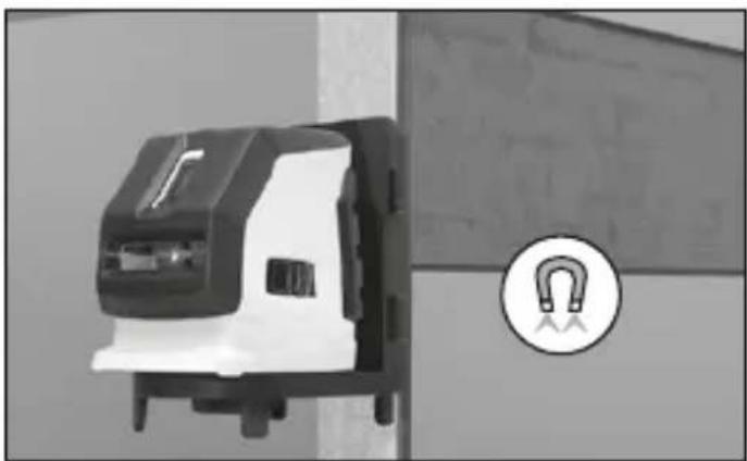
2Mounting on magnetic objects
The powerful magnets (2) at the rear allow the bracket to be fixed to magnetic objects.
natural_image
Close-up of a black and white mechanical component next to a circular logo with a U-shaped symbol (no text or labels visible)3Mounting on drywall construction profiles
natural_image
Mechanical device with directional arrow indicating movement or force (no visible text or symbols)
natural_image
Close-up of a mechanical device with open lid and control panel, mounted on a pole (no visible text or symbols)
natural_image
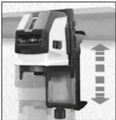
Mechanical assembly diagram showing a mounted device with mounting flanges and a separate housing, no text or symbols present.With the clamping bracket (6), the wall bracket can be mounted horizontally or vertically on drywall construction profiles.
The opening width of the clamping bracket can be adjusted with the adjustment screw (5).
The height and position of the laser can now be easily adjusted.
Danger - powerful magnetic fields
Powerful magnetic fields can adversely affect persons with active medical implants (e.g. pacemaker) as well as electromechanical devices (e.g. magnetic cards, mechanical clocks, precision mechanics, hard disks).
With regard to the effect of powerful magnetic fields on persons, the applicable national stipulations and regulations must be complied with such as BGV B11 §14 „electromagnetic fields“ (occupational health and safety - electromagnetic fields) in the Federal Republic of Germany.
To avoid interference/disruption, always keep the implant or device a safe distance of at least 30 cm away from the magnet.
Information on maintenance and care
Clean all components with a damp cloth and do not use cleaning agents, scouring agents and solvents. Store the device in a clean and dry place.
| Technical data (Subject to technical alterations. 22W02) | |
| Weight 562 g | |
| Dimensions (W x H x D) 70 x 180 x 200 mm | |
EU directives and disposal
This device complies with all necessary standards for the free movement of goods within the EU.
Further safety and supplementary notices at:
www.laserliner.com

text_image
CE UK CA!
text_image
Labeled diagram of a mechanical device with numbered parts for identification
natural_image
Three-step assembly diagram showing a device with a control panel, a black plastic housing, and a final black-and-white component (no text or symbols visible)natural_image
Close-up of a black and white mechanical component next to a circular logo with a U-shaped symbol (no text or labels visible)natural_image
Mechanical component with directional arrows indicating movement or force (no visible text or symbols)
natural_image
Close-up of a mechanical device with no visible text or symbols
natural_image
Mechanical assembly diagram showing a mounted device with mounting flanges and a separate housing, no text or symbols present.text_image
Labeled diagram of a mechanical device with numbered parts for identification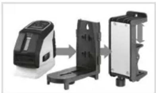
natural_image
Three-step assembly diagram showing a device, a plastic housing, and a final packaging (no text or symbols visible)natural_image
Close-up of a black and white electrical switch component next to a circular logo with a U-shaped symbol (no text or labels visible)natural_image
Mechanical device with directional arrows indicating movement or force (no visible text or symbols)
natural_image
Close-up of a mechanical device with a mounted sensor or sensor unit (no visible text or symbols)
natural_image
Mechanical assembly diagram showing a mounted device with mounting flanges and a separate view of its internal structure (no text or symbols)text_image
Labeled diagram of a mechanical device with numbered parts for identification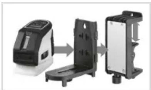
natural_image
Three-step diagram showing a device being processed into a black plastic housing, with no visible text or symbols.natural_image
Close-up of a black and white mechanical component next to a circular icon with a U-shaped symbol (no text or labels visible)natural_image
Mechanical component with directional arrows indicating movement or force (no visible text or symbols)
natural_image
Close-up of a mechanical device with no visible text or symbols
natural_image
Mechanical assembly diagram showing a mounted device with mounting flanges and a separate view of its internal structure (no text or symbols)text_image
Labeled diagram of a mechanical device with numbered parts for identification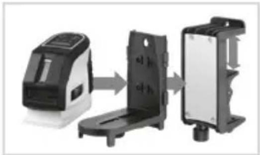
natural_image
Three-step assembly diagram showing a device with a top, a black plastic housing, and a final black-and-white component (no text or symbols visible)natural_image
Close-up of a black and white electrical switch component next to a circular logo with a U-shaped symbol (no text or labels visible)natural_image
Close-up of a mechanical device with directional arrows indicating movement or force (no visible text or symbols)
natural_image
Close-up of a mechanical device with a control panel and mounted components (no visible text or symbols)
natural_image
Mechanical assembly diagram showing a mounted device with mounting bracket and side-mounted housing (no text or symbols)text_image
Labeled diagram of a mechanical device with numbered parts for identification
natural_image
Three-step assembly diagram showing a device with a front panel, a side panel, and a back panel (no text or symbols visible)natural_image
Close-up of a black and white mechanical component next to a circular logo with a U-shaped symbol (no text or labels visible)natural_image
Mechanical component with directional arrow indicating movement or force (no visible text or symbols)
natural_image
Close-up of a mechanical device with control panel and mounted components (no visible text or symbols)
natural_image
Mechanical assembly diagram showing a mounted device with mounting flanges and a separate housing (no text or symbols visible)text_image
Labeled diagram of a mechanical device with numbered parts for identification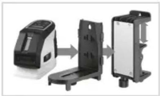
natural_image
Three-panel diagram showing a device with a control panel, a black plastic housing, and a black rectangular component (no text or symbols)natural_image
Close-up of a black and white electrical switch component next to a circular logo with a U-shaped symbol (no text or labels visible)natural_image
Mechanical component with directional arrows indicating movement or force (no visible text or symbols)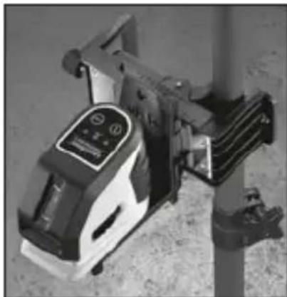
natural_image
Close-up of a mechanical device with a mounted sensor or actuator (no visible text or symbols)
natural_image
Two black plastic electrical enclosures with directional arrows indicating movement or force (no text or symbols visible)text_image
Labeled diagram of a mechanical device with numbered parts for identification
natural_image
Three black plastic electronic devices with mounting brackets, shown in sequence from left to right (no text or symbols visible)natural_image
Close-up of a black and white mechanical device mounted on a wall, with a circular icon showing a U-shaped magnet symbol (no text or labels visible)natural_image
Mechanical component with directional arrow indicating movement (no visible text or symbols)
natural_image
Close-up of a mechanical device with no visible text or symbols
natural_image
Mechanical assembly diagram showing a mounted device with mounting flanges and a separate housing, no text or symbols present.text_image
Labeled diagram of a mechanical device with numbered parts for identification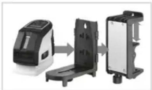
natural_image
Three-panel diagram showing a device with a top, front panel, and side panel (no text or symbols)natural_image
Close-up of a black and white electrical switch component next to a circular logo with a U-shaped symbol (no text or labels visible)natural_image
Mechanical component with directional arrow indicating movement or force (no visible text or symbols)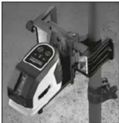
natural_image
Close-up of a mechanical device with a mounted sensor or sensor unit (no visible text or symbols)
natural_image
Mechanical assembly diagram showing a mounted device with mounting flanges and a separate housing component (no text or symbols visible)text_image
Labeled diagram of a mechanical device with numbered parts for identification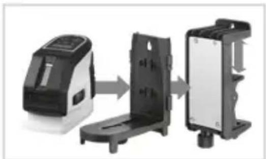
natural_image
Three-step assembly diagram showing a device, a plastic holder, and a final packaging (no text or symbols visible)natural_image
Close-up of a black and white mechanical component next to a circular logo with a U-shaped symbol (no text or labels visible)natural_image
Mechanical device component with directional arrow indicating movement (no text or symbols)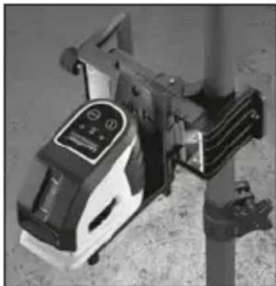
natural_image
Close-up of a mechanical device with control panel and mounted components (no visible text or symbols)
natural_image
Mechanical assembly diagram showing a mounted device with mounting flanges and a separate housing, no text or symbols present.text_image
Labeled diagram of a mechanical device with numbered parts for identification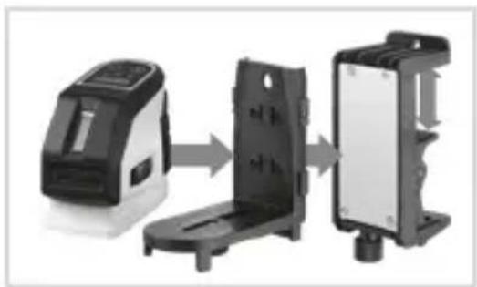
natural_image
Three-panel diagram showing a device being processed into a black plastic housing, with no visible text or symbols.natural_image
Close-up of a black and white electrical switch component next to a circular logo with a U-shaped symbol (no text or labels visible)natural_image
Mechanical device with directional arrows indicating movement or force (no visible text or symbols)
natural_image
Close-up of a mechanical device with a mounted sensor or sensor unit (no visible text or symbols)
natural_image
Mechanical assembly diagram showing a mounted device with mounting bracket and side-mounted housing (no text or symbols)text_image
Labeled diagram of a mechanical device with numbered parts for identification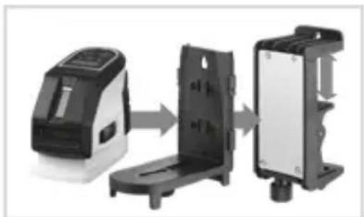
natural_image
Three-step assembly diagram showing a device, a plastic housing, and a final packaging (no text or symbols visible)natural_image
Close-up of a black and white mechanical component next to a circular logo with a U-shaped symbol (no text or labels visible)natural_image
Mechanical component with directional arrow indicating movement or force (no visible text or symbols)
natural_image
Close-up of a mechanical device with no visible text or symbols
natural_image
Mechanical assembly diagram showing a mounted device with mounting flanges and a separate housing, no text or symbols present.text_image
Labeled diagram of a mechanical device with numbered parts for identification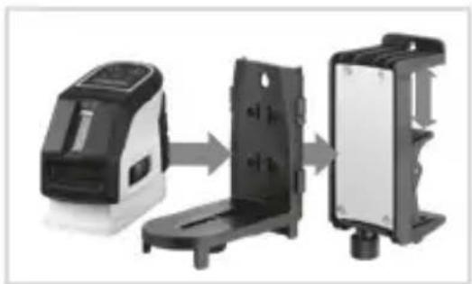
natural_image
Three-step assembly diagram showing a device, a black plastic housing, and a final black-and-white component (no text or symbols visible)natural_image
Close-up of a black and white electrical switch component next to a circular logo with a U-shaped symbol (no text or labels visible)natural_image
Close-up of a mechanical device with directional arrows indicating movement or force (no visible text or symbols)
natural_image
Close-up of a mechanical device with a mounted sensor or sensor unit (no visible text or symbols)
natural_image
Mechanical assembly diagram showing a mounted device with mounting flanges and a separate housing, no text or symbols present.text_image
Labeled diagram of a mechanical device with numbered parts for identification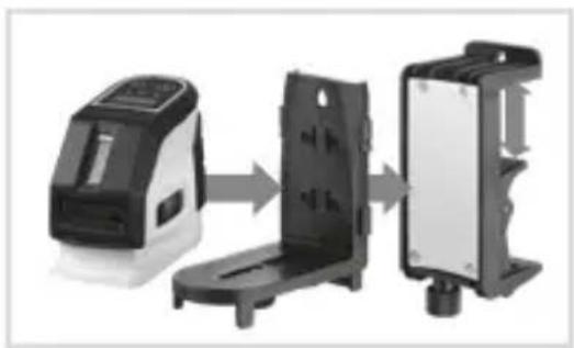
natural_image
Three-panel diagram showing a device being processed into a black plastic housing, with no visible text or symbols.natural_image
Close-up of a black and white mechanical component next to a circular logo with a U-shaped symbol (no text or labels visible)natural_image
Close-up of a mechanical device with directional arrows indicating movement or force (no visible text or symbols)
natural_image
Close-up of a mechanical device with control panel and mounted components (no visible text or symbols)
natural_image
Mechanical assembly diagram showing a mounted device with mounting flanges and a separate housing, no text or symbols present.text_image
Labeled diagram of a mechanical device with numbered parts for identification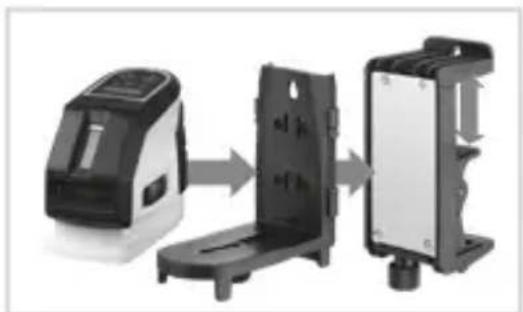
natural_image
Three-stage assembly of a device showing internal components and mounting (no text or symbols visible)natural_image
Close-up of a black and white electrical switch component next to a circular logo with a U-shaped symbol (no text or labels visible)natural_image
Close-up of a mechanical device with directional arrows indicating movement or force (no visible text or symbols)
natural_image
Close-up of a mechanical device with a mounted sensor or sensor unit (no visible text or symbols)
natural_image
Mechanical assembly diagram showing a mounted device with mounting flanges and a separate housing, no text or symbols present.text_image
Labeled diagram of a mechanical device with numbered parts for identification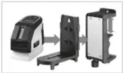
natural_image
Three-panel diagram showing a device with a control panel, a black plastic housing, and a transparent enclosure (no text or symbols)natural_image
Close-up of a black and white electronic device mounted on a wall, with a circular icon showing a U-shaped magnet symbol (no text or labels visible)natural_image
Mechanical component with directional arrow indicating movement or force (no visible text or symbols)
natural_image
Close-up of a mechanical device with control panel and mounted components (no visible text or symbols)
natural_image
Mechanical assembly diagram showing a mounted device with mounting flanges and a separate housing, no text or symbols present.text_image
Labeled diagram of a mechanical device with numbered components for identification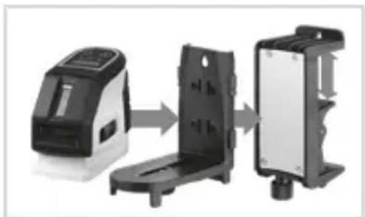
natural_image
Three-step assembly diagram showing a device moving through a black plastic housing to form a final panel (no text or symbols visible)1 Ochetă de fixare direct la perete
2 Magnet aderent deosebit de puternic (partea posterioară)
3 Filet de 1/4"
4 Şurub de fi xare 1/4"
5 Șurub de ajustare
suport de perete
6 Suportul de prindere
!
natural_image
Close-up of a black and white electrical switch component next to a circular logo with a U-shaped symbol (no text or labels visible)natural_image
Close-up of a mechanical device with directional arrows indicating movement or force (no visible text or symbols)
natural_image
Close-up of a mechanical device with a mounted sensor or sensor unit (no visible text or symbols)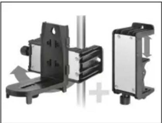
natural_image
Mechanical assembly diagram showing a mounted device with mounting flanges and a separate housing, no text or symbols present.text_image
Labeled diagram of a mechanical device with numbered parts for identification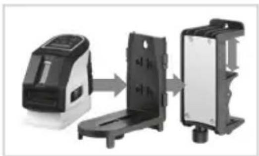
natural_image
Three-panel diagram showing a device with a sensor array, a black plastic housing, and a black rectangular device (no text or symbols)natural_image
Close-up of a black and white mechanical component next to a circular logo with a U-shaped symbol (no text or labels visible)natural_image
Close-up of a mechanical device with directional arrows indicating movement or force (no visible text or symbols)
natural_image
Close-up of a mechanical device with control panel and mounted components (no visible text or symbols)
natural_image
Mechanical assembly diagram showing two components with directional arrows, no visible text or symbolstext_image
Labeled diagram of a mechanical device with numbered parts for identification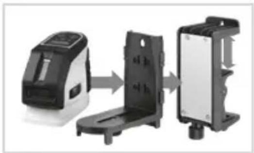
natural_image
Three-step assembly diagram showing a device moving through a housing to form a device (no text or symbols visible)natural_image
Close-up of a black and white electrical switch component next to a circular logo with a U-shaped symbol (no text or labels visible)natural_image
Close-up of a mechanical device with directional arrows indicating movement or force (no visible text or symbols)
natural_image
Close-up of a mechanical device with a mounted sensor or sensor unit (no visible text or symbols)
natural_image
Mechanical assembly diagram showing a mounted device with mounting flanges and a separate housing, no text or symbols present.text_image
Labeled diagram of a mechanical device with numbered parts for identification
natural_image
Three-step assembly diagram showing a device moving through a housing to form a device (no text or symbols visible)natural_image
Close-up of a black and white mechanical device mounted on a wall, with a circular logo featuring a U-shaped symbol (no text or labels visible)natural_image
Mechanical component with directional arrow indicating movement or force (no visible text or symbols)
natural_image
Close-up of a mechanical device with a control panel and mounted components (no visible text or symbols)
natural_image
Two mechanical components with directional arrows indicating motion, no visible text or symbolstext_image
Labeled diagram of a mechanical device with numbered parts for identification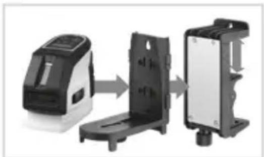
natural_image
Three-step assembly diagram showing a device with a front panel, a back panel, and a final packaging (no text or symbols visible)natural_image
Close-up of a black and white electrical switch component next to a circular logo with a U-shaped symbol (no text or labels visible)natural_image
Mechanical device with directional arrows indicating movement or force (no visible text or symbols)
natural_image
Close-up of a mechanical device with a mounted sensor or sensor unit (no visible text or symbols)
natural_image
Mechanical assembly diagram showing a mounted device with mounting flanges and a separate housing, no text or symbols present.text_image
Labeled diagram of a mechanical device with numbered parts for identification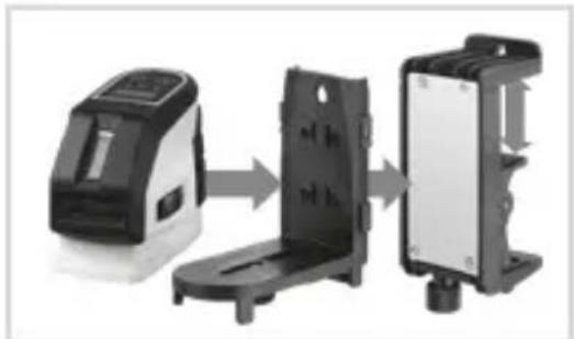
natural_image
Three-step assembly diagram showing a device moving through a metal frame to form a final device (no text or symbols visible)natural_image
Close-up of a black and white mechanical device mounted on a wall, with a circular icon showing a U-shaped magnet symbol (no text or labels visible)natural_image
Mechanical component with directional arrow indicating movement or force (no visible text or symbols)
natural_image
Close-up of a mechanical device with control panel and mounted components (no visible text or symbols)
natural_image
Mechanical assembly diagram showing a mounted device with mounting flanges and a separate housing (no text or symbols visible)text_image
Technical diagram of a mechanical device with numbered parts labeled 1 through 6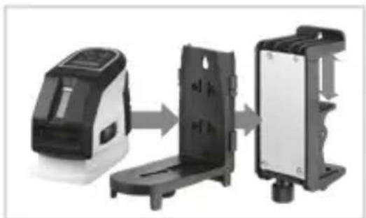
natural_image
Three-step diagram showing a device being processed into a plastic housing (no text or symbols visible)1 Ušica za pričvršćivanje izravno na zidu
2 Snažni magneti za držanje (stražnja strana)
3 Navojem 1/4"
4 Pričvrsni vijak 1/4"
5 Vijak za namještanje steznog držača
6 Stezni držač
!
Opasnost od prignječenja! Nikad ne posežite rukom u stezni držač!
Laserliner
1Pričvršćivanje na zidu
natural_image
Close-up of a black and white electrical switch component next to a circular logo with a U-shaped symbol (no text or labels visible)natural_image
Mechanical device with directional arrows indicating movement or force (no visible text or symbols)
natural_image
Close-up of a mechanical device with a mounted sensor or sensor unit (no visible text or symbols)
natural_image
Mechanical assembly diagram showing a mounted device with mounting flanges and a separate housing, no text or symbols present.Pomoću steznog držača (6) zidni se držač može pričvrstiti vodoravno i okomito na profilima za suhu gradnju.
Vijak za namještanje (5) omogućava namještanje širine otvora steznog držača. Na taj se način mogu jednostavno namještati visina i položaj lasera.
Opasnost od jakih magnetskih polja
Snažna magnetska polja mogu prouzročiti štetne učinke na ljude s aktivnim pomoćnim tvarima (kao što je pejsmejker) i elektromehaničkim uređajima (kao što su magnetske kartice, mehanički satovi, precizna mehanika, tvrdi diskovi).
S obzirom na učinak jakih magnetskih polja ljude, potrebno je uzeti u obzir odgovarajuće nacionalne propise i regulacije, kao što je npr.
natural_image
Architectural diagram showing ceiling framework and a magnified inset of a structural detail (no text or symbols)SERVICE

Umarex GmbH & Co. KG
- Laserliner -