
ELVOX 41000 - Intercom Vimar - Free user manual and instructions
Find the device manual for free ELVOX 41000 Vimar in PDF.
| Product type | Basic audio electronic module for Pixel Series modular plates, usable on installations with Due Fili Plus technology. |
| Dimensions (approximate) | 105 x 105 x 35 mm (module only) |
| Weight (approximate) | 200 g |
| Power supply | Via Due Fili bus, nominal voltage 28 Vdc (21-28 Vdc), max absorption 300 mA. |
| Main functions | Automatic gain control, echo canceller, automatic address configuration, 4 basic call buttons (expandable up to 54 with additional modules 41010), electric lock control, MiniUSB connector for configuration via SaveProg software. |
| Maintenance and cleaning | Clean with a soft dry cloth. Do not use abrasive products or solvents. |
| Safety | Protection degree IP54 (protection against dust and water splashes), impact protection index IK08. |
| Spare parts and repairability | Additional modules: 41010 (buttons), 41015 (name holders). Configuration via SaveProg software downloadable from www.vimar.com. MiniUSB connector for programming. |
| General information | Brand Vimar, model ELVOX 41000, category Intercom. Compatible with Due Fili Plus. Operating temperature: -25°C to +55°C. |
Frequently Asked Questions - ELVOX 41000 Vimar
User questions about ELVOX 41000 Vimar
0 question about this device. Answer the ones you know or ask your own.
Ask a new question about this device
Download the instructions for your Intercom in PDF format for free! Find your manual ELVOX 41000 - Vimar and take your electronic device back in hand. On this page are published all the documents necessary for the use of your device. ELVOX 41000 by Vimar.
USER MANUAL ELVOX 41000 Vimar
The instruction manual is downloadable from the site www.vimar.com
Table of Contents
Installation rules .... 3 Regulatory compliance .... 3 Description .... 3 Technical characteristics .... 3 Installation procedure .... 3 Front and rear view .... 9 Wiring diagram .... 11 Configurations .... 17 Advanced configuration (via PC) .... 21
Installation rules
Installation should be carried out by qualified personnel in compliance with the current regulations regarding the installation of electrical equipment in the country where the products are installed.
Conformity
EMC directive
Standards EN 60065, EN 61000-6-1 and EN 61000-6-3.

WEEE - Information for users
If the crossed-out bin symbol appears on the equipment or packaging, this means the product must not be included with other general waste at the end of its working life. The user must take the worn product to a sorted waste center, or return it to the retailer when purchasing a new one. Products for disposal can be consigned free of charge (without any new purchase obligation) to retailers with a sales area of at least 400m ^2 , if they measure less than 25cm. An efficient sorted waste collection for the environmentally friendly disposal of the used device, or its subsequent recycling, helps avoid the potential negative effects on the environment and people's health, and encourages the re-use and/or recycling of the construction materials.
Description
Standard audio electronic module for Pixel Series modular panels, can be used on systems with Due Fili Plus technology. Can be combined with additional 10-button modules (41010) and a name-holder entrance panel module (41015), via the supplied harness.
This electronic module is equipped with:
- automatic gain control on the power supplied by the loud-speaker, depending on the type of installation;
- echo suppressor, to remove the Larsen effect;
- automatic configuration of indoor unit addresses;
- automatic configuration of speech unit addresses;
- four conventional indoor unit call buttons in two rows (2+2).
- can manage up to 54 button calls, using the additional button modules 41010.
- control of an electric lock connected directly to terminals S+ and S- and connection of a local additional button for lock opening at terminals CA+ and CA- (terminals CA+ and CA-
can alternatively be configured via SaveProg software as the input of a sensor for signalling "Door Open".
- front MiniUSB connector for connecting a PC via a USB-Mini-iUSB cable, for configuration using the Due Fili Plus system management software "Save Prog", which can be downloaded from the website www.vimar.com.
- Standard configurations can be made by using the four front call buttons and their four indicator LEDs.
Technical specifications
- Power supply from Due Fili Bus, via terminals 1 and 2:
28VDC nominal.
- Minimum voltage on terminals 1 and 2: 21VDC
- Absorption from the Bus:
| Situation 41000 | |
| on Stand-by 25 mA | |
| in communication 120 mA | |
| lock activation + 50 mA | |
| maximum additional modules + 130 mA | |
| maximum | 300 mA |
The maximum current delivered to the additional electronic modules (back panel) is 500mA (maximum 5 additional modules).
Refer to the additional modules for sizing the load on the back panel and on the bus.
- Operating temperature: -25 °C / +55°C.
- Protection class: IP54
- IK08-rated for protection against impact (Pixel)
Installation procedure.
- Install box, trim and frame, following the relevant instructions.
- Secure the audio electronic unit and any other additional modules to the pins of the frames;
- Connect the additional electronic modules in cascade with the audio electronic unit, using the supplied harness;
- Connect the terminal block of the audio unit.
- Configure and program the parameters of the entrance panel, using the USB of the audio module.
- Complete the installation of the mechanical parts.
Replacing or removing electronic modules.
Proceed as follows:
- Disconnect the terminal block from the audio electronic unit.
- Disconnect the harnesses of the additional electronic modules from the standard electronic unit.
- Remove/replace the modules.
- Connect the new additional electronic modules with the audio unit.
- Reconnect the audio unit.
- Make the necessary configurations for the operation of the replaced additional modules.
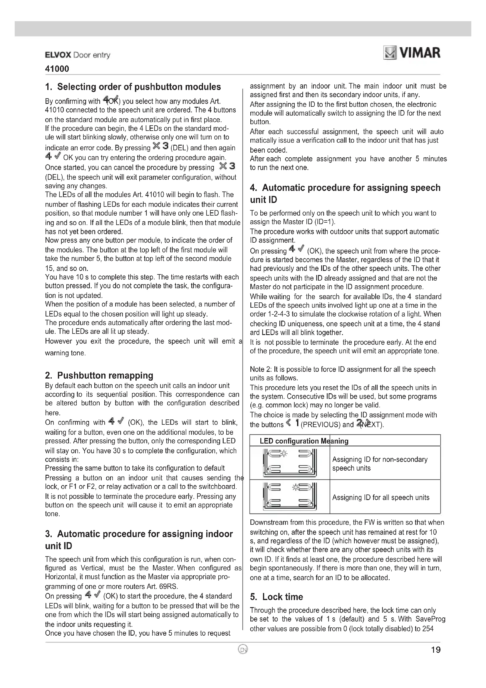
a) Loudspeaker
b) Microphone
e) Call buttons
f) Mini USB connector for configuration via PC and specific software.
h) Removable wiring terminal block
i) Connector for wiring to additional electronic modules (via harness 41191)
Description of wiring terminal block
| Terminal function | |
| B2 | Due Fili Bus |
| B1 | |
| CA+ | Lock control additional button (Default). Alternatively (if configured via SaveProg), sensor input to signal “Door Open”. |
| CA- | |
| S+ | Electric lock output |
| S- | |
Note: S+/S- outputs. The entrance panel supplies a current peak I_T>1A for 10ms after which there follows a holding current I_M=200mA for the entire duration of the lock command (see lock time).
F - System power supply unit
L - Electric lock 12 VDC
P - Lock control additional button
X - Twisted pair cable
natural_image
Diagram showing a computer setup with an open chassis connected to a laptop via USB cable (no text or symbols present)Configuration
The electronic module is configured via the "SaveProg" system software.
However, some parameters can be modified via the electronic module itself, using the 4 standard buttons and their 4 indicator LEDs, or with the LCD when installed. In some cases the buttons and LEDs of the additional modules are used too.
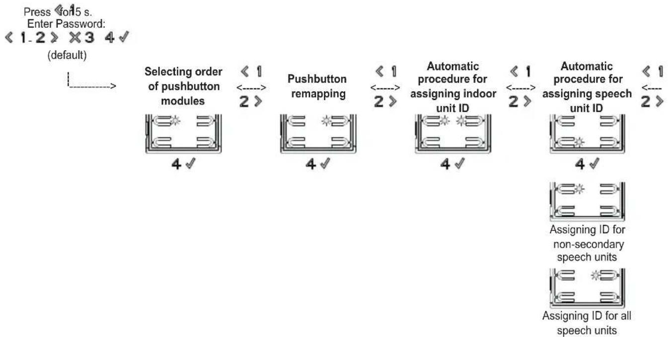
Configuration input
The procedure is activated, from the state of rest of the speech unit, by pressing and holding the < 1 button for 5 s. After this time the speech unit will emit a tone. Release the < 1 button and, within 30 s, press the sequence of buttons forming the password. The timeout is renewed each time the button is pressed, so there are 30 s from the tone after which the speech unit goes back to rest.
By default the password is:

Activation is confirmed by a tone.
To navigate in choosing the time to be configured, only the 4 standard buttons are used; the numbering and the function of the buttons is as follows:
< 1 PREVIOUS: to return to the previous sequence.
2> NEXT: to move on to the next sequence.
X3 DEL: to exit the configuration menu or a configuration editing phase, cancelling the selected one.
4 √ OK: to go from the sequence menu to configuration editing or to confirm the change to a configuration.
The standard LEDs instead indicate in which configuration you are selecting by pressing 4 √ (OK).
The correspondence is as follows:
| LED configuration Meaning (Parameter) | |
 | Selecting order of pushbutton modules |
 | Pushbutton remapping |
 | Automatic procedure for assigning indoor unit ID |
 | Automatic procedure for assigning speech unit ID |
 | Lock time |
 | Conversation time |
 | Audio level |
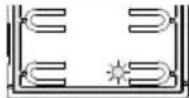 | Reset factory settings / Restart / External Memory Reset |
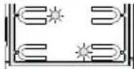 | Default pushbutton grouping |
Pressing the ✗3 button (DEL) at this level sets it back to rest. Press 4 √ (OK) to enter the specific configuration.
Configuration sequence
flowchart
graph LR
    A["Selecting order of pushbutton modules"] --> B["Pushbutton remapping"]
    B --> C["Automatic procedure for assigning indoor unit ID"]
    C --> D["Automatic procedure for assigning speech unit ID"]
    D --> E["Assigning ID for non-secondary speech units"]
    E --> F["Assigning ID for all speech units"]
1. Selecting order of pushbutton modules
By confirming with 4OK) you select how any modules Art. 41010 connected to the speech unit are ordered. The 4 buttons on the standard module are automatically put in first place. If the procedure can begin, the 4 LEDs on the standard module will start blinking slowly, otherwise only one will turn on to indicate an error code. By pressing ✗3 (DEL) and then again 4 √ OK you can try entering the ordering procedure again. Once started, you can cancel the procedure by pressing ✗3 (DEL), the speech unit will exit parameter configuration, without saving any changes.
The LEDs of all the modules Art. 41010 will begin to flash. The number of flashing LEDs for each module indicates their current position, so that module number 1 will have only one LED flashing and so on. If all the LEDs of a module blink, then that module has not yet been ordered.
Now press any one button per module, to indicate the order of the modules. The button at the top left of the first module will take the number 5, the button at top left of the second module 15, and so on.
You have 10 s to complete this step. The time restarts with each button pressed. If you do not complete the task, the configuration is not updated.
When the position of a module has been selected, a number of LEDs equal to the chosen position will light up steady.
The procedure ends automatically after ordering the last module. The LEDs are all lit up steady.
However you exit the procedure, the speech unit will emit a warning tone.
2. Pushbutton remapping
By default each button on the speech unit calls an indoor unit according to its sequential position. This correspondence can be altered button by button with the configuration described here.
On confirming with 4 √ (OK), the LEDs will start to blink, waiting for a button, even one on the additional modules, to be pressed. After pressing the button, only the corresponding LED will stay on. You have 30 s to complete the configuration, which consists in:
Pressing the same button to take its configuration to default Pressing a button on an indoor unit that causes sending the lock, or F1 or F2, or relay activation or a call to the switchboard. It is not possible to terminate the procedure early. Pressing any button on the speech unit will cause it to emit an appropriate tone.
3. Automatic procedure for assigning indoor unit ID
The speech unit from which this configuration is run, when configured as Vertical, must be the Master. When configured as Horizontal, it must function as the Master via appropriate programming of one or more routers Art. 69RS.
On pressing 4 √ (OK) to start the procedure, the 4 standard LEDs will blink, waiting for a button to be pressed that will be the one from which the IDs will start being assigned automatically to the indoor units requesting it.
Once you have chosen the ID, you have 5 minutes to request
assignment by an indoor unit. The main indoor unit must be assigned first and then its secondary indoor units, if any.
After assigning the ID to the first button chosen, the electronic module will automatically switch to assigning the ID for the next button.
After each successful assignment, the speech unit will auto matically issue a verification call to the indoor unit that has just been coded.
After each complete assignment you have another 5 minutes to run the next one.
4. Automatic procedure for assigning speech unit ID
To be performed only on the speech unit to which you want to assign the Master ID (ID=1).
The procedure works with outdoor units that support automatic ID assignment.
On pressing 4 √ (OK), the speech unit from where the procedure is started becomes the Master, regardless of the ID that it had previously and the IDs of the other speech units. The other speech units with the ID already assigned and that are not the Master do not participate in the ID assignment procedure.
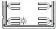
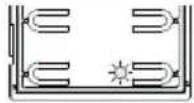
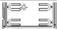
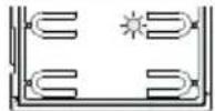
While waiting for the search for available IDs, the 4 standard LEDs of the speech units involved light up one at a time in the order 1-2-4-3 to simulate the clockwise rotation of a light. When checking ID uniqueness, one speech unit at a time, the 4 standard LEDs will all blink together.
It is not possible to terminate the procedure early. At the end of the procedure, the speech unit will emit an appropriate tone.
Note 2: It is possible to force ID assignment for all the speech units as follows.
This procedure lets you reset the IDs of all the speech units in the system. Consecutive IDs will be used, but some programs (e.g. common lock) may no longer be valid.
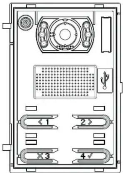
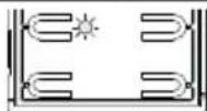
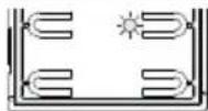
The choice is made by selecting the ID assignment mode with the buttons 1 (PREVIOUS) and 2 (NEXT).
| LED configuration Meaning | |
 | Assigning ID for non-secondary speech units |
 | Assigning ID for all speech units |
Downstream from this procedure, the FW is written so that when switching on, after the speech unit has remained at rest for 10 s, and regardless of the ID (which however must be assigned), it will check whether there are any other speech units with its own ID. If it finds at least one, the procedure described here will begin spontaneously. If there is more than one, they will in turn, one at a time, search for an ID to be allocated.
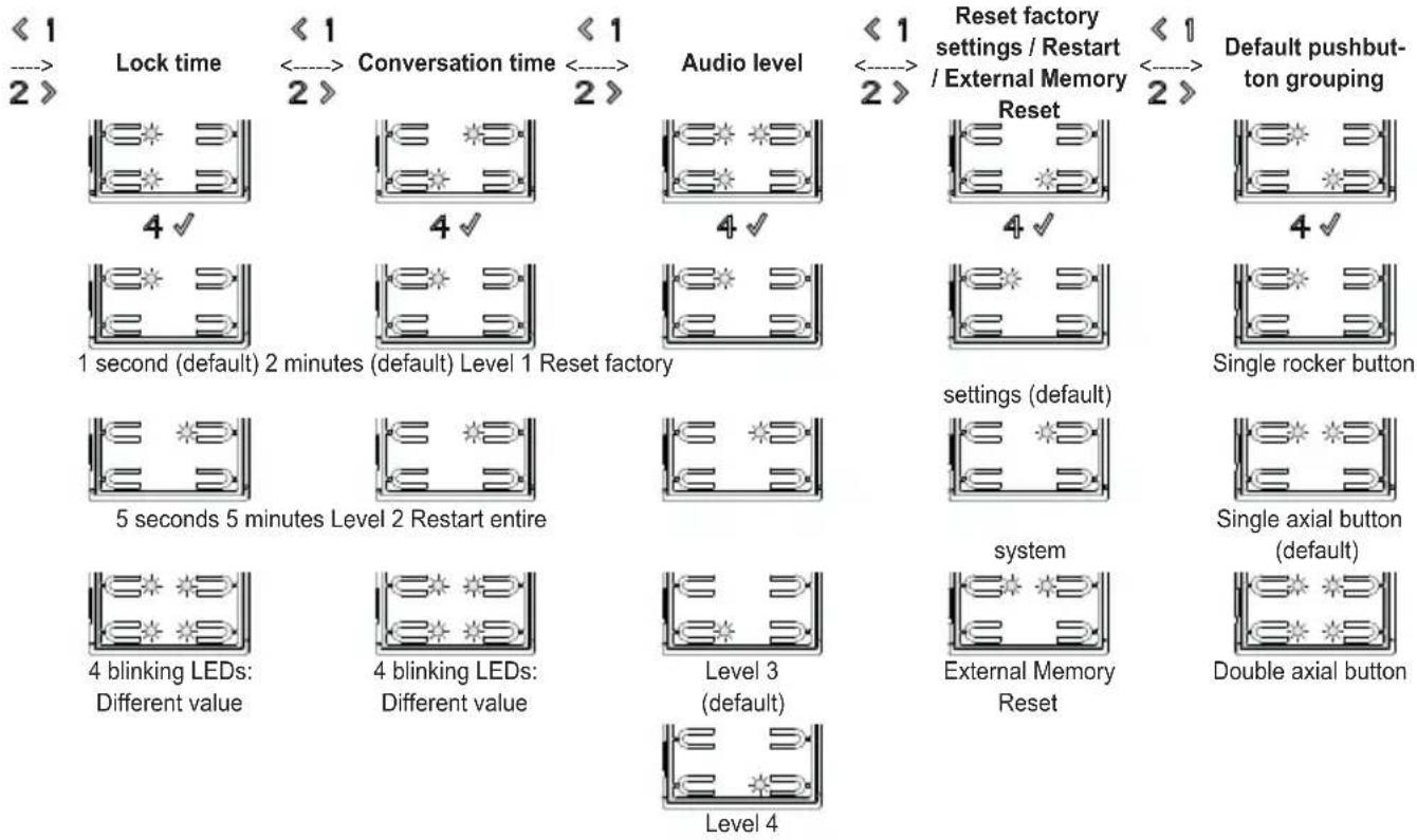
5. Lock time
Through the procedure described here, the lock time can only be set to the values of 1 s (default) and 5 s. With SaveProg other values are possible from 0 (lock totally disabled) to 254
41000
s. If this has been done previously, all 4 LEDs will blink to alert you that you are changing a configuration that then cannot be restored using the procedures stated here.
| LED configuration Meaning | |
 | 1 second (default) |
 | 5 seconds |
 | All 4 LEDs are flashing:Different value to the above |
The 1 (PREVIOUS) and 2(NEXT) buttons change between the possible values. If you try to go before the first or after the last one, the speech unit will emit a tone to warn you that there are no other valid values.
If you start from a configuration with the LEDs flashing, first pressing the < 1 button (PREVIOUS) will set the first possible value, while pressing the 2 > button (NEXT) will set the last possible one.
Pressing ✗ 3 (DEL) takes you back to the previous level, without saving any changes.
Press 4 √ (OK) to confirm what you have chosen.
6. Conversation time
Through the procedure described here, the talk time can only be set to the values of 2 (default) and 5 minutes. With SaveProg other values are possible from 10 to 2540 s. If this has been done previously, all 4 LEDs will blink to alert you that you are changing a configuration that then cannot be restored using the procedures stated here.
| LED configuration Meaning | |
 | 2 minutes (default) |
 | 5 minutes |
 | All 4 LEDs are flashing: Different value to the above |
The ≤ 1 (PREVIOUS) and 2(NEXT) buttons change between the possible values. If you try to go before the first or after the last one, the speech unit will emit a tone to warn you that there are no other valid values.
If you start from a configuration with the LEDs flashing, first pressing the < 1 button (PREVIOUS) will set the first possible value, while pressing the 2 > button (NEXT) will set the last possible one.
The self-start and response times have not changed, while with SaveProg the call, self-start and talk times are all set in-
dependently.
Pressing ✗3 (DEL) takes you back to the previous level, without saving any changes.
Press 4 √ (OK) to confirm what you have chosen.
7. Audio level
The audio level is configurable on 4 levels.
| LED configuration Meaning | |
 | Level 1 |
 | Level 2 |
 | Level 3 (default) |
 | Level 4 |
Pressing ✗3 (DEL) takes you back to the previous level, without saving any changes.
Press 4 √ (OK) to confirm what you have chosen.
8. Reset factory settings / Restart / External Memory Reset
| LED configuration Meaning | |
 | Reset factory settings (default) |
 | Restart entire system |
 | External Memory Reset (contacts list, access keys, remapping) |
On confirming "reset factory setting" with 4 √ (OK), the speech unit will emit a continuous tone for 8 s. During this time you need to press the 4 √ button (OK) 3 times. If this step is not completed, the speech unit will go into its rest state.
On confirming "restart entire system", the indoor unit will instruct all the devices in the system in which it is installed to restart, after which it will itself restart. It is functionally equivalent to pressing the reset button on the Master speech unit of the previous generations.
Confirming the External Memory Reset deletes any names in the contacts list, entry codes and button remapping.
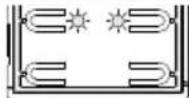
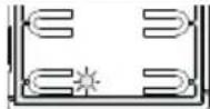
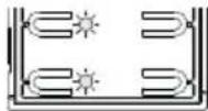
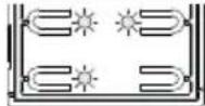
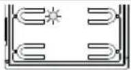
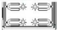
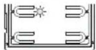
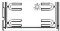
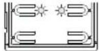
9. Default pushbutton grouping
By confirming with 4OK) you choose how the speech unit
41000
will group the buttons for the calls.
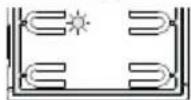
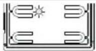
By default the speech units come with the buttons grouped in twos horizontally to use the single axial button Art. 41110. This button can actuate one or both mechanical buttons on the same row.
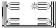
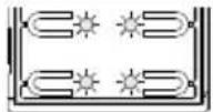
There is also the single rocker button, Art. 41111, that lets you actuate the single mechanical button and the double axial button Art. 41112 which actuates up to 4 buttons.
The < 1 (PREVIOUS) and 2(NEXT) buttons change between the possible values. If you try to go before the first or after the last one, the speech unit will emit a tone to warn you that there are no other valid values.
If you start from a configuration with the LEDs flashing, first pressing the < 1 button (PREVIOUS) will set the first possible value, while pressing the 2 > button (NEXT) will set the last possible one.
| Article Description LED | |
| 41111 Single rocker button | 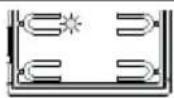 |
| 41110 Single axial button (default) | 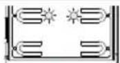 |
| 41112 Double axial button | 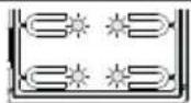 |
Pressing (DEL) takes you back to the previous level, without saving any changes.
Press 4 √ (OK) to confirm what you have chosen.
Note: For the 10 button module Art. 41010, by selecting the Double axial button mode, the last pair of buttons is forced to Single axial button.
With SaveProg you can change the grouping in a totally arbitrary manner, except that the last row of each module cannot be configured as a Double axial button.
The following figure outlines the configurations of the speech unit and a button module in the three possible cases and their respective indoor units corresponding to each group. For calls, reference is made to the first external module.
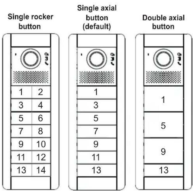
The chosen positioning for the indoor units, with gaps in the numbering, means you don't have to re-code the existing indoor units or have to re-configure the existing speech units, if the button grouping is later changed either with this procedure or with SaveProg.
Advanced configuration (via PC)
The advanced configuration of the electronic module is performed via a PC, using the "SaveProg" Due Fili system management software, available from the website www.vimar.com, and connecting the electronic module to the PC via a USB-MiniUSB cable.
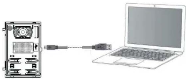
natural_image
Diagram showing a computer setup with an external CPU and connected to a laptop (no text or symbols present)Configuration
natural_image
Technical diagram of a computer drive rear panel with labeled ports and connectors (no text or symbols beyond component labels)
natural_image
Diagram showing a computer setup with an external CPU and connected to a laptop (no text or symbols present)Konfiguration
natural_image
Technical diagram of a device rear panel with labeled ports and connectors (no readable text or symbols)natural_image
Diagram showing a laptop connected to an internal device via cable, with no visible text or symbols.Configuración
natural_image
Technical diagram of a computer drive rear panel with labeled ports and connectors (no text or symbols beyond basic labels)
natural_image
Diagram showing a computer setup with an external CPU and connected to a laptop (no text or symbols visible)Configuração
natural_image
Diagram of an electronic device rear panel with labeled ports and connectors (no text or symbols beyond basic labels)natural_image
Diagram showing a computer setup with an internal CPU and connected to a laptop (no text or symbols present)Διαμόρφωση
natural_image
Technical diagram of a device rear panel with labeled ports and connectors (no text or symbols beyond basic labels)< 1
natural_image
Diagram showing a laptop connected to an internal device via cable, with no visible text or symbols.


- Table of Contents
- Installation rules
- Conformity
- WEEE - Information for users
- Description
- Technical specifications
- Installation procedure.
- Replacing or removing electronic modules.
- Description of wiring terminal block
- Configuration
- Configuration input
- Configuration sequence
- Selecting order of pushbutton modules
- Pushbutton remapping
- Automatic procedure for assigning indoor unit ID
- Automatic procedure for assigning speech unit ID
- Lock time
- 41000
- Conversation time
- Audio level
- Reset factory settings / Restart / External Memory Reset
- Default pushbutton grouping
- Advanced configuration (via PC)
- Konfiguration
- Configuración
- Configuração
- Διαμόρφωση
Brand : Vimar
Model : ELVOX 41000
Category : Intercom