Compact 10 - Boiler Tesy - Free user manual and instructions
Find the device manual for free Compact 10 Tesy in PDF.

| Product type | Electric storage water heater |
| Brand | Tesy |
| Model | Compact 10 |
| Nominal volume | 10 liters |
| Nominal voltage | 230 V |
| Nominal power | 2000 W |
| Maximum working pressure | 0.6 MPa (6 bars) |
| Safety valve pressure | 0.8 MPa (8 bars) |
| Inner lining | Vitreous enamel (GC) |
| Corrosion protection | Magnesium anode |
| Mounting type | Above or below the sink (universal) |
| Hydraulic connection | G 1/2 (thread) |
| Anti-freeze function | Yes (anti-freeze mode) |
| Adjustable thermostat | Yes (gradual) |
| Indicator lights | Red (heating), blue (temperature reached) |
| Maximum temperature | 75 °C (approx.) |
| Daily energy consumption | See energy label Annex I |
| Load profile | See Annex I |
| Mixed water volume at 40°C (V40) | See Annex I |
| Energy efficiency of hot water production | See Annex I |
| Periodic maintenance | Descaling every 2 years, anode check |
| Thermal protection | Thermal limiter (automatic shutdown) |
| Protection rating | IPX4 (suitable for bathroom) |
| Approximate net weight | 15 kg |
| Approximate dimensions (H x W x D) | 40 x 40 x 50 cm |
Frequently Asked Questions - Compact 10 Tesy
User questions about Compact 10 Tesy
0 question about this device. Answer the ones you know or ask your own.
Ask a new question about this device
Download the instructions for your Boiler in PDF format for free! Find your manual Compact 10 - Tesy and take your electronic device back in hand. On this page are published all the documents necessary for the use of your device. Compact 10 by Tesy.
USER MANUAL Compact 10 Tesy
EN ELECTRIC WATER HEATER 7-11 Instructions for use and maintenance
natural_image
Exterior view of a modern TESY vacuum cleaner (no text or symbols visible on body)I. ВАЖНИ ПРАВИЛА
- This technical description and instructions manual was prepared in order to acquaint you with the product and the conditions of proper installation and use. These instructions were also intended for use by qualified technicians, who shall perform the initial installation, or disassembly and repairs in the event of a breakdown.
- Following the current instructions will primarily be of interest to the consumer, but along with this, it is also one of the warranty conditions, pointed out in the warranty card, so that the consumer can benefit from the free warranty services. The producer is not responsible for damages in the appliance that have appeared as a result of operation and/or installation not corresponding to the instructions here.
- The electric water heater complies with the requirements of EN 60335-1, EN 60335-2-21.
- This appliance can be used by children aged from 8 years and above and persons with reduced physical, sensory or mental capabilities or lack of experience and knowledge if they have been given supervision or instruction concerning use of the appliance in a safe way and understand the hazards involved.
- Children shall not play with the appliance.
- Cleaning and user maintenance shall not be made by children without supervision.

Attention! Improper installation and connection of the appliance may make it hazardous for the health and life of consumers. It may cause grievous and permanent consequences, including but not tied to physical injuries and/or death. Improper installation and connection of the appliance may also to damage to the consumers' property /damage and/ or destruction/, or to that of third persons, as a lot of, but not limited to flooding, explosion and/or fire.
Installation, connection to the main water and power supply, and putting into operation must be carried out by certified electricians and technical personnel certified in installation of this category of appliances, who have obtained their license in the state where the installation and commissioning of the appliance are carried out, and in compliance with its local legislation.

All alterations and modifications to the water heater's construction and electrical circuitry are forbidden. If such alterations or modifications are established during inspection, the appliance's warranty shall be null void. Alterations and modifications shall mean each instance of removal of elements incorporated by the manufacturer, building in of additional components into the water heater, replacement of elements by similar parts unapproved by the manufacturer.
Mounting
- The water heater must only be mounted in premises with normal fire resistance.
- In the event the device is mounted in a bathroom, the selected location must exclude the possibility of water spray contact from the showerhead or portable showerhead attachment.
- The water heater is designed to operate only in closed and heated premises where the temperature is not lower than 4^ C and it is not designed to operate in a continuous protracted regime.
- The appliance is affixed to a wall by means of mounting brackets attached to the unit's body. Two hooks are used to fix the appliance (min. ∅ 4 mm) firmly on the wall (included in the mounting set).
Water heater connection
- The appliance is intended to supply hot water to household sites equipped with a piping system working at pressure below 6 bar (0,6 Mpa).
- .The safety return-valve must be mounted on the cold water supply pipe, in observance of the direction arrow stamped on its body, indicating the incoming water's direction. Additional stopcocks must not be mounted between the safety return-valve and the water heater.
Exception: If the local regulations (norms) require the usage of another protection valve or mechanism (in accordance with EN 1487 or EN 1489), then it must be bought additionally. For mechanisms operating in accordance with EN 1487 the announced operational pressure must be no more than 0.7 MPa. For other protection valves, the pressure at which they are calibrated must be 0.1 MPa lower than the one marked on the appliance's sign. In these cases the safety valve which the appliance is supplied with should not be used. - The safety valve and the pipe between the valve and the water heater must be protected from freezing. During hose draining - its free end must be always open to the atmosphere (not to be immersed). Make sure that the hose is also protected from freezing.
EN
-
In order to secure the water heater's safe operation, the safety return-valve must undergo regular cleaning and inspections for normal functioning /the valve must not be obstructed/, and for the regions with highly calcareous water it must be cleaned from the accumulated lime scale. This service is not provided under warranty maintenance.
-
In order to prevent injury to user and third persons in the event of faults in the system for providing hot water, the appliance must be mounted in premises outfitted with floor hydro insulation and plumbing drainage. Don't place objects, which are not waterproof under the appliance under any circumstances. In the event of mounting the appliance in premises not outfitted with floor hydro insulation, a protective tub with a plumbing drainage must be placed under the appliance.
-
During operation – regime of heating the water – water drops through the drainage opening of the protection valve are usual. The protection valve should be left open to the atmosphere. Measures should be taken to lead and collect the leakages in order to prevent damages.
-
If the probability exists for the premise's temperature to fall below 0^ C, the water heater must be drained. In the event you must empty the water heater, first you must cut off its power supply.
Draining procedure for boilers designed to be installed ABOVE SINKS:
- First shut the cold water supply valve
- Open the hot water valve on the mixing-faucet
- The water tap 7 (fig 4a) must be opened to drain the water from water tank. If there is no such tap build in the pipe line, than the water can be drain directly from inlet pipe of water tank after when you disconnect it from water main
Draining procedure for boilers designed to be installed UNDER SINKS:
- Switch the boiler off the power supply network.
- Dismantle the connecting water fittings from the boiler.
- Disassemble the boiler from its installation place, turn it so the pipes point to the floor and pour the water in a vessel you have prepared for the purpose. Wait until all the water drains out of the boiler.
Connection to the electrical network
- Do not switch on the water heater unless you established it was filled with water..
- Upon connecting the water heater to the electric mains care must be taken to connect the safety lead.
- Models without power cord, the circuit has to be supplied with a safety fuse (16A) and with inbuilt device to ensure disconnection of all pole pieces in the conditions of over-voltage from category III.
- If the power supply cord (of models that have one) is damaged, it must be replaced by a service representative or a person with similar qualification, to avoid any risk.
- During the heating the appliance could produce a hissing noise (the boiling water). This is common and does not indicate any damage. The noise gets higher with the time and the reason for this is the accumulation of limestone. To remove the noise the appliance must be cleaned from limestone. This type of cleaning is not covered by the warranty.
Dear Clients,
The TESY team would like to congratulate you on your new purchase. We hope that your new appliance shall bring more comfort to your home.
II. TECHNICAL SPECIFICATIONS
- Nominal volume V, liters - see the appliance's rating plate
- Nominal voltage - see the appliance's rating plate
- Nominal power consumption - see the appliance's
rating plate - Nominal pressure - see the appliance's rating plate
ATTENTION! This is not the water mains pressure. Th
is the pressure that is announced for the appliance and refers to the requirements of the safety standards.
-
Water heater type - closed accumulating water heater, with thermal insulation
-
Inner coating: GC-glass-ceramics
- Daily energy consumption – see Annex I
B. Rated load pro-le - see Annex I - Quantity of mixed water at 40°C V40 litres - see Annex I
- Maximum temperature of the thermostat - see Annex 1
- Default temperature settings - see Annex I
- Energy efficiency during water heating - see Annex 1
III. DESCRIPTION AND PRINCIPLE OF OPERATION
The appliance is designed to operate in regions where the water hardness is not more than 10PdH. In case that it is installed in a region where the water is harder it is possible that limestone precipitation accumulate very fast. This can cause a speci c noise during heating, as well as fast damaging of the electrical part. For regions with harder water yearly cleaning of the limestone precipitation in the appliance is recommended, as well as usage of not more than 2 kW of heating power
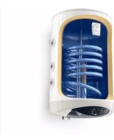
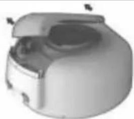
The appliance consists of a body, angle, plastic control panel, safety return valve.
- The body consists of a steel reservoir (water tank) and plastic housing (outer shell) with thermal insulation placed in-between, and two pipes with thread G V ^2 , for cold water supply (marked with a blue ring) and hot water discharge (marked with a red ring). The inner reservoir is made of steel proved against corrosion by a special glass-ceramic coating
-
The angle is tied with electric heater and magnesium anode protector. The angle is fixed to the water tank with bolts.
The electric heater heats the water in the tank and is controlled by the thermostat, which automatically maintains the preset temperature.
The plastic control panel incorporates switch (depending on model), adjustable thermostat (depending on model), and thermal cut-out and control lamps.
The thermal cut-out is a device, which switches the heater of the power supply when the water temperature reaches -
The safety-return valve prevents the appliance's complete emptying in the event of cold water supply interruption. The valve protects the appliance from pressure increases higher than the allowed value during heating (1 pressure will increase when temperature increases), by releasing the excess pressure through the drain outlet. Water dropping out through the drains during the warning process is a normal event that must be taken into consideration when the boiler is installed.
ATTENTION! The safety-return valve cannot protect the
appliance in the event of water mains pressure in excess
of the acceptable pressure stated for the appliance.
IV. INSTALLATION AND SWITCH ON
Attention! Improper installation and connection of the
appliance may make it hazardous for the health and life of consumers. It may cause serious and adverse
consequences, including but not limited to physical injuries and/or
death. Improper installation and connection of the appliance may
also lead to damage to the consumers' property /damage and/or
destruction', or to that of third persons, as a result of, but not limited to, unding, explosion peeling, to
Installation, connection to the main water and power supply, and
putting into operation must be carried out by certified electricians
and technical personnel certified in installation of this category of
apprentices, where have been limited to increase in the share of the installation and commissioning of the appliance are carried out
and in compliance with its local legislation.
1. Installation
We recommend installation of the device at close
proximity to locations where hot water is used, in order
to replace heat hoses during water transportation. The selected location must exclude the possibility of water
spray originating from the showerhead or other water
contact
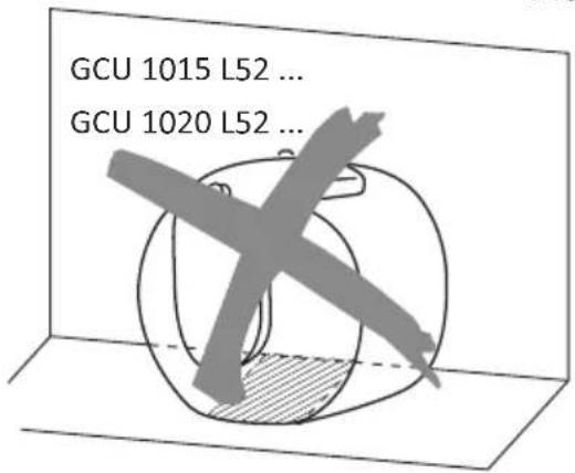
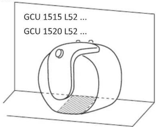
• Appliances designed for installation above sinks are
assembled in such a manner that the outlet/inlet pipes are
pointed downwards (to the "out of the premise).
The appliance is a xed to a wall by means of mounting
brackets attached to the unit's body. Two books are used (or, as the amplifier (min. Q 4 mm) - only on the wall).
(a) - The appliance (main, set, turn) - They are the main (included in the mounting set).
(二) 12 (三)
• Appliances designed for installation under sinks are
assembled in such a manner that the odded-inlet pipes are pointed upwards (to the ceiling of the premise).
The well-known we have played standing on the one as
The appliances can be placed according to the "out of mounted on the wall."
(1) 2017年1月1日至2018年1月1日
In case you want to mount the appliance on the wall, the
suspension must be done with two hooks (mill. D/4 mill) securely attached to the wall.
IMPORTANT: The type of appliance designed to be
LIM ORIANT: The type of appliance designed to be installed UNDER / ABOVE a sink is marked on the
appliance.
ATTENTION! In order to prevent injury to user and third persons in the event of faults in the hot water supply system, the appliance must be mounted in premises outfitted with floor hydro insulation and sewer drainage. Don't place objects, which are not waterproof under the appliance under any circumstances. In the event of mounting the appliance in premises without floor hydro insulation, a protective tank with a sewer discharge drainage must be placed under the appliance.

Notice: the set does not include a protective tub and the user must select the same.
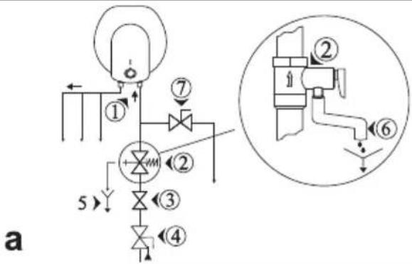
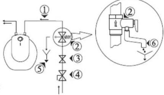
2. Water heater connection to the water supply system
Fig.4a - installation scheme above sink
Fig.4b - installation scheme under sink
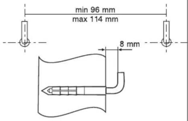
Where: 1 – input pipe, 2 – safety valve (0.8 MPa), 3 – reduction valve (if the water supply pressure exceeds 0.6 MPa), 4 – stop valve, 5 – bell-mouth discharge to the sewer, 6 – hose;
7 - Drain water tap.
Upon connecting the water heater to the water supply system, take care of the indicative color markings /rings/ of the pipes:
BLUE - for cold /in-flowing/ water,
RED - for hot /out-flowig/ water.
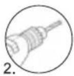
The mounting of the safety return-valve supplied with the water heater is obligatory. The safety return-valve must be installed on the cold water supply pipe, according to the arrow stamped on its body that indicates the supplied water direction.
Exception: If the local regulations (norms) require the usage of another protection valve or mechanism (in accordance with EN 1487 or EN 1489), then it must be bought additionally. For mechanisms operating in accordance with EN 1487 the announced operational pressure must be no more than 0.7 MPa. For other protection valves, the pressure at which they are calibrated must be 0.1 MPa lower than the one marked on the appliance's sign. In these cases the safety valve which the appliance is supplied with should not be used.

ATTENTION! Other type of stopping armature is not allowed between the protection return valve (the live device) and the appliance.

ATTENTION! Any other /old/ safety return-valves may lead to a failure of your appliance, therefore they are removed.

ATTENTION! Fixing the safety return-valve to threads longer than 10 mm is not allowed, as it could need the valve and could make the use of your force dangerous.

ATTENTION! The safety valve and the pipe between the valve and the water heater must be protected from g. During hose draining - its free end must be always to the atmosphere (not to be immersed). Make sure that he is also protected from freezing.
The boiler is filled with water by opening the tap on the cold water supply system and the tap on the hot water mixing faucet. After the filling process is complete, a constant stream of water should flow from the water-mixing faucet. Now you can shut the hot water tap on the mixing faucet.
When you must empty the water heater, you should first cut it off the power supply.
Draining procedure for boilers designed to be installed ABOVE SINKS:
-
First shut the cold water supply valve
-
Open the hot water valve on the mixing-faucet
-
The water tap 7 (fig 4a) must be opened to drain the water from water tank. If there is no such tap build in the pipe line, than the water can be drain directly from inlet pipe of water tank after when you disconnect it from water main

IMPORTANT: When draining the boiler, take measures to prevent damages caused by the flowing water.
Draining procedure for boilers designed to be installed UNDER SINKS:
-
Switch the boiler off the power supply network.
-
Dismantle the connecting water fittings from the boiler.
-
Disassemble the boiler from its installation place, turn it so the pipes point to the floor and pour the water in a vessel you have prepared for the purpose. Wait until all the water drains out of the boiler.
In case that the pressure in the water mains is over the value pointed out in the above paragraph I, then it is necessary to assemble a pressure reduce valve, otherwise the water heater would not function properly. The Manufacturer does not assume any liability for problems arising out of the appliance's improper use.
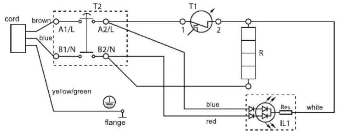
3. Water heater's electrical connection (fig.3)

ATTENTION! Before you switch the power supply, make sure the appliance is full of water.
3.1. Models fit with power supply cord combined with a plug shall be plugged in a socket. The boiler can be disconnected from the power supply by unplugging.

ATTENTION! The wall-plug must be properly connected to a separate electrical circle that is used with a protector. It must be earthed.
3.2. Water heaters fitted with a supply cord without a plug
The appliance has to be connected to a separate electricity circuit of the stationary electrical wiring. The connecting has to be constant- with no plug contacts. The circuit has to be supplied with a safety fuse (16A) (20A for power > 3700W) and with inbuilt device to ensure disconnection of all pole pieces in the conditions of over-voltage from category III.
The connecting of the conductors of the supply cord of the appliance has to be carried out as follows:
- conductor with brown insulation – to the phase conductor of the electrical wiring (L)
● conductor with blue insulation- to the neutral conductor of the wiring (N) - conductor with yellow-green insulation – to the safety conductor of the wiring (⊥)
3.3. Models without power supply cord
The appliance has to be connected to a separate electricity circuit of the stationary electrical wiring. The circuit has to be supplied with a safety fuse 16A. Copper single core (rigid – non stranded) conductor shall be used for the connection – cable 3 x 1.5 mm ^2 for power 2000 W.
The electrical circuit supplying the appliance must have an in-built device ensuring the splitting of all terminal poles under conditions of super-voltage of category III.
In order to fix the power cable to the water heater, it is necessary to remove the plastic cover (fig.5). The power leads connections must be in accordance with the terminal markings of the thermal circuit breaker:
- the phase cable must be connected to the A1 (11) terminal
• the neutral, to the B1 (21) terminal - and the protection terminal, obligatory to the marked screwed joint
The power supply cord can be fixed to the plastic control panel with a cable stop. After the installation, the plastic cover must be replaced in its original position!
Explanations to Fig.3:
T1 – thermal regulator, T2 – thermal circuit breaker, IL1 – light indicator, R – heater
Before initial start of the device, please make sure that the water heater has been correctly connected to the electrical network and that it is filled up with water.
Switching on the water heater is done through the device incorporated in the installation, which is described in sub-item 3.2 of paragraph V, or by inserting the plug into an electrical socket (for models with cord with a plug).
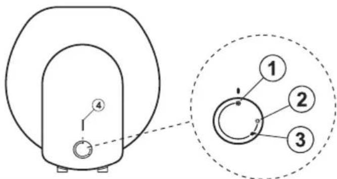
Clarification to Fig.6:
Operation modes:
- Position ( anti-freezing mode

WARNING: The electrical power supply of the device should be switched on. The safety valve and the pipe connecting it to the device must be secured against freezing.
- Position ( ) maximum temperature
- Position ( ) at this mode the water temperature reaches about 60^ C. In this way heat losses are reduced.
- Light indicator – at heating mode it is lit in red, and it is lit in blue when the water has been heated up and the thermostat has switched off.
- Regulator knob – for temperature setting
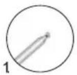
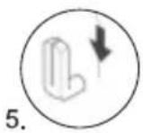
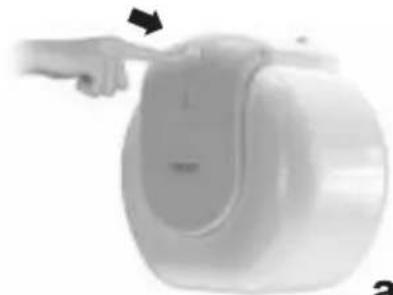
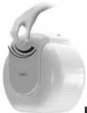
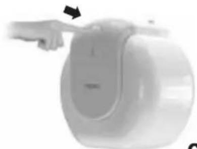
Water heaters with electrical-mechanical POP-UP operation:
- Push the knob to pop-up Fig. 7a.
- Set the temperature of the water heater Fig. 7b This setting allows for gradual temperature adjustment.
- Push the knob to retract Fig. 7c
WARNING! Once a month set the knob to the position 'maximum temperature' for a period of 24 hours (unless the device is constantly operated in this mode). Thus you will ensure better hygiene of the heated water.
VI. RUST PROTECTION MAGNESIUM ANODE
The magnesium anode protects the water tank's inner surface from corrosion. The anode element is an element undergoing wear and tear and is subject to periodic replacement. This is cost for the user.
In view of the long-term and accident free use of your water heater, the manufacturer recommends periodic inspections of the magnesium anode's condition by a qualified technician and replacement whenever required, and this could be performed during the appliance's technical preventive maintenance.
For replacements, please contact the authorized service stations!
VII. PERIODIC MAINTENANCE
Under normal use of the heater, under the influence of high temperature, lime scale /the so-called lime scale layer/ is deposited upon the heating element's surface. This worsens the heat exchange between the heating element and water. The heating element's surface temperature increases along /of boiling water/. The thermoregulator begins to switch on and off more frequently. A "deceptive" activation of the thermal protection is possible. Due to these facts, the manufacturer recommends preventive maintenance of your water heater every two years by an authorized service center or service base. This protective maintenance must include cleaning and inspection of the anode protector (for water heaters with glass-ceramic coating), which shall be replace with a new one if need arises.
In order to clean the appliances use a damp cloth. Do not clean with abrasive or solvent content detergents. Do not pour water over the appliance.
The manufacturer does not bare the responsibility for all consequences caused by not obeying the instructions, given hereby.
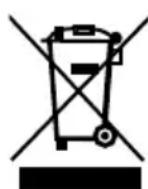
Environmental protection instructions.
Old electric appliances contain precious materials and must not be disposed with the domestic waste! Please make your active contribution to the protection of the environment and dispose of the appliance in the stations organized for the purpose (if
available).
RU
I. ВАЖНЫЕ ПРАВИЛА
2C
Floor instalacion
3
4
flowchart
graph TD
    A["Valve ①"] --> B["Pump"]
    B --> C{Actuator ②}
    C --> D["Valve ③"]
    C --> E["Actuator ④"]
    D --> F["Flow Indicator ⑤"]
    E --> G["Flow Indicator ⑥"]
    H["Top Left Panel"] --> I["Top Right Panel"]
    style A fill:#f9f,stroke:#333
    style H fill:#f9f,stroke:#333
b
flowchart
graph TD
    A["①"] --> B["②"]
    B --> C["③"]
    C --> D["④"]
    D --> E["⑤"]
    E --> F["⑥"]
    style A fill:#f9f,stroke:#333
    style B fill:#ccf,stroke:#333
    style C fill:#cfc,stroke:#333
    style D fill:#fcc,stroke:#333
    style E fill:#cff,stroke:#333
    style F fill:#ffc,stroke:#333
5
natural_image
3D rendered object resembling a dome-shaped container with small protrusions (no text or symbols)a
natural_image
Exterior view of a modern office building (no signage)b
natural_image
Exterior view of a modern office building (no signage)C
6
7
natural_image
Close-up of a white spherical device with a hand adjusting its lid, showing no visible text or symbols.a
natural_image
White hand holding a small white device with a handle, resembling a kitchen or cleaning tool (no visible text or symbols)b
natural_image
Close-up of a hand pressing down on a white cylindrical device (no visible text or symbols)C

natural_image
Abstract geometric shape resembling a stylized arrow or chevron, rendered in gray tones with no text or symbols.TESY
TESY Ltd
Shumen, 9700, 48 Blvd. Madara,
PHONE: +359 54 859 129,
office@tesy.com
ТЕСИ ООД
9701 гр. Шумен, бул. Мадара 48,
PHONE: +359 54 859 129,
office@tesy.com