
BLK 1.6 LE - Power tool Fein - Free user manual and instructions
Find the device manual for free BLK 1.6 LE Fein in PDF.
| Product type | Portable nibbler |
| Brand | Fein |
| Model | BLK 1.6 LE |
| Power input (P1) | 350 W |
| Power output (P2) | 210 W |
| No-load stroke rate | 800–1500 min⁻¹ |
| Cutting speed | 2.3 m/min |
| Max. steel thickness (400 N/mm²) | 1.6 mm |
| Max. steel thickness (600 N/mm²) | 1.0 mm |
| Max. steel thickness (800 N/mm²) | 0.7 mm |
| Max. aluminum thickness (250 N/mm²) | 2.5 mm |
| Insertion diameter | 24 mm |
| Min. inner radius | 65 mm |
| Weight (according to EPTA) | 1.9 kg |
| Sound pressure level (LpA) | 90.2 dB (uncertainty 3 dB) |
| Sound power level (LwA) | 101.2 dB (uncertainty 3 dB) |
| Vibration emission value (ah) | 4.1 m/s² (uncertainty 1.5 m/s²) |
| Power supply | Single-phase, 230 V / 50 Hz |
| Double insulation | Yes |
| Recommended protection | Residual current circuit breaker 30 mA max. |
| Application | Dry cutting of sheet metal (straight or small radius curves) |
| Authorized working tools | Specific Fein punch and die |
| Maintenance | Blow with compressed air, lubricate contact surfaces |
| Warranty | Statutory warranty + manufacturer declaration |
Frequently Asked Questions - BLK 1.6 LE Fein
User questions about BLK 1.6 LE Fein
0 question about this device. Answer the ones you know or ask your own.
Ask a new question about this device
Download the instructions for your Power tool in PDF format for free! Find your manual BLK 1.6 LE - Fein and take your electronic device back in hand. On this page are published all the documents necessary for the use of your device. BLK 1.6 LE by Fein.
USER MANUAL BLK 1.6 LE Fein
natural_image
Illustration of a handheld electric shaver with brand logo and connector port (no text or symbols on body)BLK1.3TE (**)
BLK1.3CSE (**) 7 232 ...
BLK1.6E (**) 7 232 ...
BLK1.6LE (**)
BLK2.0E (**)
BLK3.5 (**)
BLK5.0 (**) 7 232 ...
7 232 ...
7 232 ...
7 232 ...
7 232 ...
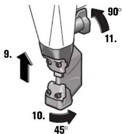
natural_image
Diagram showing a piston-cranked engine with two cylindrical components, one with an arrow indicating motion (no text or symbols)
BLK1.3TE/CSE (**)
BLK1.6E (**)
BLK2.0E (**)
BLK1.6LE (**)


natural_image
Diagram showing a mechanical component with two cylindrical parts and an arrow indicating direction (no text or symbols)BLK3.5 (**)

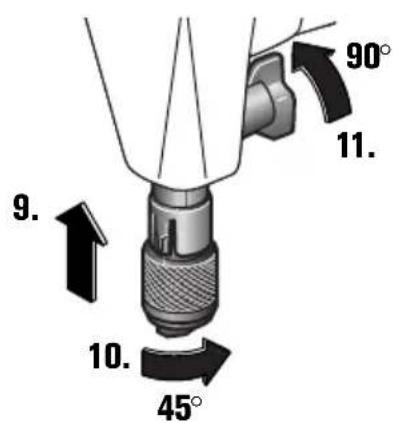


natural_image
Diagram showing a piston-cranked engine with two cylindrical components, one with directional arrows indicating movement or force (no text or symbols)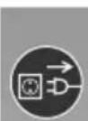
BLK5.0 (**)


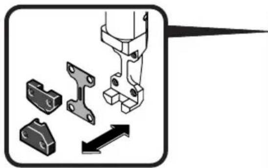
natural_image
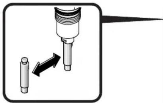
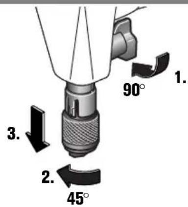
Mechanical component assembly diagram showing bracket, housing, and pin alignment (no text or symbols)BLK1.6LE (**)


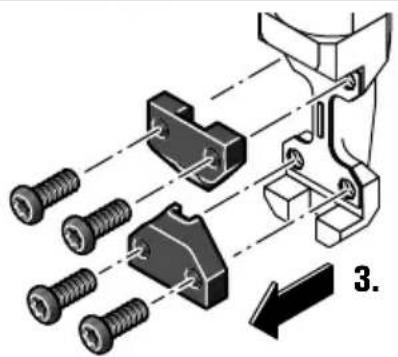
natural_image
Mechanical assembly diagram showing bolted connection to a bracket with mounting holes (no text or symbols)
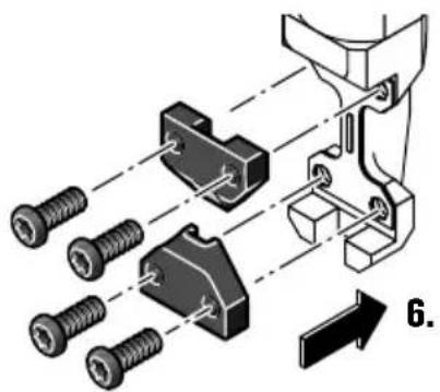
natural_image
Mechanical assembly diagram showing bolted connection to a bracket with mounting holes (no text or symbols)
natural_image
Diagram of a mechanical component with an arrow indicating direction (no text or symbols)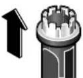


Translation of the Original Instructions.
Symbols, abbreviations and terms used.
| Symbol, character Explanation | |
 | Make sure to read the enclosed documents such as the Instruction Manual and the General Safety Instructions. |
 | Observe the instructions in the text or graphic opposite! |
 | Observe the instructions in the text or graphic opposite! |
 | General prohibition sign. This action is prohibited. |
| [ZWZZ2] | Before commencing this work step, pull the mains plug out of the socket. Otherwise there will be danger of injury if the power tool should start unintentionally. |
 | Use eye protection during operation. |
 | Use ear protection during operation. |
 | Use protective gloves during operation. |
 | Gripping surface |
 | Confirms the conformity of the power tool with the directives of the European Community. |
 | Confirms the conformity of the power tool with the directives of Great Britain (England, Wales, Scotland). |
 | This sign indicates a possible dangerous situation that could cause severe or fatal injury. |
 | Worn out power tools and other electrotechnical and electrical products should be sorted separately for environmental-friendly recycling. |
 | Switching on |
 | Switching off |
| [###] | Product with double or reinforced insulation |
| [###] | Steel |
| — [###] | Aluminium |
| [ZZAS] | Plastic |
—  | Low stroke rate |
 | High stroke rate |
| (**) may contain numbers and letters | |
| (Ax - Zx) Marking for internal purposes | |
| Character Unit of measurement, international | Unit of measurement, national | Explanation |
| P1 | W W Power input | |
| P2 | W | O u t |
| Character | Unit of measurement, international | Unit of measurement, national | Explanation |
| n0 | /min, min -1 , rpm, r/min | rpm Stroke rate at no-load | |
| nS | m/min m/min Cutting speed | ||
| UV | V | R | a t e |
| fHz Hz Frequency | |||
| M... | mm mm Size of metric thread | ||
| ∅ mm mm Diameter of a round part | |||
| Fe 400 | mm mm Max. work-piece thickness for steel with up to 400 N/mm 2 | ||
| Fe 600 | mm mm Max. work-piece thickness for steel with up to 600 N/mm 2 | ||
| Fe 800 | mm mm Max. work-piece thickness for steel with up to 800 N/mm 2 | ||
| Al 250 | mm mm Max. work-piece thickness for aluminium with up 250 N/mm 2 | ||
| mm mm Diameter of pilot-drill for inside cut-outs | |||
| mm mm Min. inside curve radius | |||
| kg kg Weight according to EPTA-Procedure 01 | |||
| LpA | dB | dB | Sound pressure level |
| LwA | dB | dB | Sound power level |
| LpCpeak | dB | dB | Peak sound pressure level |
| K... | Uncertainty | ||
| a | m/s 2 | m/s 2 | Vibrational emission value according to EN 62841 (vector sum of three directions) |
| ah | m/s 2 | m/s 2 | Vibrational emission value |
| m, s, kg, A, mm, V, W, Hz, N, °C, dB, min, m/s 2 | m, s, kg, A, mm, V, W, Hz, N, °C, dB, min, m/s 2 | Basic and derived units of measurement from the international system of units SI. | |
For your safety.
WARNING
Read all safety warnings and all instructions. Failure to follow the
warnings and instructions may result in electric shock, fire and/or serious injury.
Save all warnings and instructions for future reference.

Do not use this power tool before you have thoroughly read and completely understood this Instruction Manual and the enclosed "General
Safety Instructions" (document number 3 41 30 465 06 0). The documents mentioned should be kept for later use and enclosed with the power tool, should it be passed on or sold.
Please also observe the relevant national industrial safety regulations.
Intended use of the power tool:
Hand-guided nibbler for cutting sheet metal, cut-outs and tight curves in weather-protected environments without water supply using the application tools and accessories recommended by FEIN.
BLK3.5/BLK5.0 ( ** ): This power tool is also suitable for use with AC generators with sufficient power output that correspond to the Standard ISO 8528, design type G2. This Standard is particularly not complied with when the so-called distortion factor exceeds 10 %. When in doubt, please refer to the generator instruction/specification guide.
Special safety instructions.
Use auxiliary handle(s), if supplied with the tool. Loss of control can cause personal injury.
Wear personal protective equipment. Depending on application, use face shield, safety goggles or safety glasses. Where appropriate, wear dust mask, hearing protectors, gloves and workshop apron capable of stopping small abrasive or workpiece fragments. The eye protection must be capable of stopping flying debris generated by various operations. The dust mask or respirator must be capable of filtrating particles generated by your operation. Prolonged exposure to high intensity noise may cause hearing loss.
Secure the work piece firmly. A work piece that is gripped tightly in a clamping device or vice, is more secure than if held by hand.
Do not rivet or screw any name-plates or signs onto the power tool. If the insulation is damaged, protection against an electric shock will be ineffective. Adhesive labels are recommended.
Do not use accessories which are not specifically designed and recommended by the power tool manufacturer. Safe operation is not ensured merely because an accessory fits your power tool.
Clean the ventilation openings on the power tool at regular intervals using non-metal tools. The blower of the motor draws dust into the housing. An excessive accumulation of metallic dust can cause an electrical hazard.
Before putting into operation, check the mains connection and the mains plug for damage.
Recommendation: The tool should always be supplied with power via a residual current device (RCD) with a rated current of 30 mA or less.
Hand/arm vibrations
The vibration emission level given in this information sheet has been measured in accordance with a standardised test given in EN 62841 and may be used to compare one tool with another. It may be used for a preliminary assessment of exposure.
The declared vibration emission level represents the main applications of the tool. However, if the tool is used for different applications, with different accessories or poorly maintained, the vibration emission may differ. This may significantly increase the exposure level over the total working period.
An estimation of the level of exposure to vibration should also take into account the times when the tool is switched off or when it is running but not actually doing the job. This may significantly reduce the exposure level over the total working period.
Identify additional safety measures to protect the operator from the effects of vibration such as: maintain the tool and the accessories, keep the hands warm, organisation of work patterns.
Operating Instructions.

Guide the power tool toward the work piece only when switched on.
While cutting, hold the power tool as upright as possible to the work-piece surface.
Guide the power tool uniformly and with light feed in the cutting direction. Excessive feed reduces the tool life of the application tools.
Do not cut steel sheets where welded. Do not cut layered sheets exceeding the max. work-piece thickness.
To increase the tool life of punch and die, it is recommended to apply a lubricating agent alongside the intended cutting line:
- For cuts in steel sheet: Cutting paste or cutting oil, - For cuts in aluminium: Petroleum.
For inside cuts, a pilot hole is required; see "Technical Data" for diameters.
Do not switch the power tool off until after having removed it from the cutting path.
The symptom for worn punches and dies are a clearly increased feed force at lower working progress.
BLK1.3TE ( )/BLK1.3CSE ( )/BLK1.6E ( )/BLK1.6LE ( ): Punch and die cannot be reground.
BLK2.0E (**)/BLK3.5 (**)/BLK5.0 (**): The punch – not the die – can be reground as long as the length of the reground punch does not fall below the minimum die length.
| Die Minimum punch length | |
| BLK2.0E (**): | |
| 3 13 09 040 00 2 45 mm | |
| BLK3.5 (**): | |
| 3 13 09 093 00 3 51.5 mm | |
| 3 13 09 094 00 1 51.5 mm | |
| BLK5.0 (**): | |
| 3 13 09 109 00 2 58.8 mm | |
| 3 13 09 107 00 0 56.6 mm | |
| 3 13 09 108 00 8 54.5 mm | |
BLK2.0E (**)/BLK3.5 (**): For template cuts, the template is traced via the lower cylindrical part of the punch guide. The clearance between template and the actual cutting edge is 2.5 mm.
The template should be at least 2 mm thick; the total thickness of template and work piece may not exceed 5.5 mm.
BLK1.6E ( ** ): For cutting deep-channel trapezoidal sheet metal, the optionally available profile set 160 can be mounted. (see page 14)
Repair and customer service.


When working metal under extreme operating conditions, it is possible for conductive dust to settle in the interior of the power
tool. The total insulation of the power tool can be impaired. Blow out the interior of the power tool via the ventilation slots frequently with dry and oil-free compressed air, and connect a residual current device (RCD) on the line side.

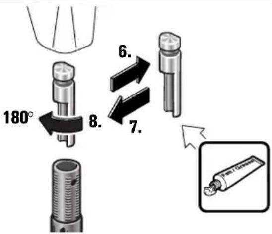
Lightly grease the sliding surfaces between die holder and punch.
Products that have come into contact with asbestos may not be sent in for repair. Dispose of products contaminated with asbestos according to the applicable country-specific regulations for such disposal.
When the machine's power supply cord is damaged, it must be replaced by the manufacturer or their representative.
If required, you can change the following parts yourself: Application tools
Warranty and liability.
The warranty for the product is valid in accordance with the legal regulations in the country where it is marketed. In addition, FEIN also provides a guarantee in accordance with the FEIN manufacturer's warranty declaration.
The delivery scope of your power tool may include only a part of the accessories described or shown in this Instruction Manual.
Declaration of conformity.
This CE declaration is only valid for European Union and EFTA (European Free Trade Association) countries and only for products intended for the EU- or EFTA market. After placing the product on the EU market the UKCA mark loses its mark validity.
The UKCA declaration is only valid for the Great Britain market (England, Wales and Scotland) and only for products intended for the Great Britain market. After placing the product on the Great Britain market the CE mark loses its mark validity.
FEIN declares itself solely responsible for this product conforming with the relevant provisions given on the last page of this Instruction Manual.
Technical documents at: C. & E. Fein GmbH, D-73529 Schwäbisch Gmünd
Environmental protection, disposal.
Packaging, worn out power tools and accessories should be sorted for environmental-friendly recycling.
Miljøvern, deponering.
BLK2.0E ( ** ):
3 13 09 040 00 2 45 mm
BLK3.5 ( ** ):
3 13 09 093 00 3 51,5 mm
3 13 09 094 00 1 51,5 mm
BLK5.0 ( ** ):
3 13 09 109 00 2 58,8 mm
3 13 09 107 00 0 56,6 mm
3 13 09 108 00 8 54,5 mm
China RoHS Status Certificate
中国 RoHS 认证概况
Table of Toxic and Hazardous Substances/Elements and their Content
as required by China's Management Methods for Controlling Pollution by Electronic Information Products
有毒有害物质 / 成分及其含量表
This CE declaration is only valid for European Union and EFTA (European Free Trade Association) countries and only for products intended for the EU- or EFTA market. After placing the product on the EU market the UKCA mark loses its mark validity.

DIN EN 62841-1:2015 + AC:2015
Director of Quality Director of Product Management Development
The UKCA declaration is only valid for the Great Britain market (England, Wales and Scotland) and only for products intended for the Great Britain market. After placing the product on the Great Britain market the CE mark loses its mark validity.

BS EN 62841-1:2015 + AC:2015
BS EN 62841-2-8:2016
BS EN 55014-1:2017 + A11:2020
BS EN 55014-2:2015
BS EN 55014-2:1997+A1:2001+A2:2008+AC:1997
BS EN 61000-3-2:2014
BS EN 61000-3-2:2019
BS EN 61000-3-3:2013+A1:2019
Suppl y of Machinery Regulations 2008,
EMC Regulation 2006, The Restriction of the Use of Certain Hazardous Substances In ectrical and Electronic Equipment Regulations 2012
U. Hergosell
i. V. S. Böhm i. V. Dr. M. Hergesell
Director of Quality Director of Product Management Development


- Symbols, abbreviations and terms used.
- For your safety.
- WARNING
- Intended use of the power tool:
- Special safety instructions.
- Hand/arm vibrations
- Operating Instructions.
- Repair and customer service.
- Warranty and liability.
- Declaration of conformity.
- Environmental protection, disposal.
- Miljøvern, deponering.
- China RoHS Status Certificate
- 中国 RoHS 认证概况
Brand : Fein
Model : BLK 1.6 LE
Category : Power tool