
K5208 - Drain cleaning machine RIDGID - Free user manual and instructions
Find the device manual for free K5208 RIDGID in PDF.

| Product Type | Electric Drain Cleaning Machine |
| Brand | RIDGID |
| Model | K5208 |
| Cleaning Capacity | 50 to 200 mm (2" to 8") |
| Supported Cable Diameters | 22 mm (7/8") and 32 mm (1-1/4") |
| Maximum Cable Length | 61 m (200 ft) |
| Motor | Induction, 3/4 HP |
| No-Load Speed | 700 rpm |
| Power Supply | 120 V~ 60 Hz, 10.4 A (other voltages available) |
| Weight | 24 kg (54 lb) |
| Controls | Forward / Stop / Reverse, clutch lever |
| Safety | Integrated GFCI, motor thermal protection |
| Included Equipment | RIDGID drain cleaning glove, stop cable guide, pin wrench |
| Routine Maintenance | Cleaning, lubricating cable couplings, adjusting clutch jaws, belt tension |
| Spare Parts | Sectional cables, cleaning tools, gloves, clutch jaws, belt, front cable guide |
| Reparability | Repair by RIDGID authorized center, original parts required |
| Warranty | Lifetime Warranty (Full Lifetime Warranty) |
Frequently Asked Questions - K5208 RIDGID
User questions about K5208 RIDGID
0 question about this device. Answer the ones you know or ask your own.
Ask a new question about this device
Download the instructions for your Drain cleaning machine in PDF format for free! Find your manual K5208 - RIDGID and take your electronic device back in hand. On this page are published all the documents necessary for the use of your device. K5208 by RIDGID.
USER MANUAL K5208 RIDGID
K-5208 Drain Cleaning Machine
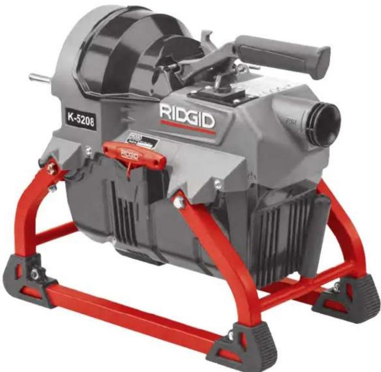
Table of Contents
Recording Form For Machine Serial Number 1
Safety Symbols 2
General Power Tool SafetyWarnings
Work Area Safety 2
Electrical Safety 2
Personal Safety 3
Power Tool Use and Care 3
Service 3
Specific Safety Information 3
Drain Cleaner Safety 4
RIDGID Contact Information. 4
Description 4
Specifications 5
Standard Equipment. 6
Pre-Operation Inspection. 6
Machine and Work Area Set-Up 7
Connecting/Disconnecting Sectional Cable Couplings 9
Operating Instructions 10
Feeding The Cable Into The Drain 10
Passing Through Traps Or Other Transitions 12
Cleaning The Drain 12
Working The Blockage 12
Handling A Stuck Tool/Cable End 12
Freeing A Stuck Tool 13
Retrieving The Cable. 13
Draining The Machine 13
Preparing For Transport 14
Storage 14
Maintenance Instructions 14
Cleaning 14
Lubrication 14
Jaw/Clutch Adjustment 14
Changing Clutch Jaw Assembly. 15
Changing Belt. 15
Belt Tensioning. 16
Changing Front Nose Piece 16
Motor Thermal Overload 16
Troubleshooting 17
Service And Repair 17
Optional Equipment 17
Disposal 18
EC Declaration of Conformity . Inside Back Cover
Lifetime Warranty. Back Cover
*Original Instructions - English
Drain Cleaner
K-5208 Drain Cleaning Machine


WARNING!
Read this Operator's Manual carefully before using this tool. Failure to understand and follow the contents of this manual may result in electrical shock, fire and/or serious personal injury.
| K-5208 Drain Cleaning Machine | |
| Record Serial Number below and retain product serial number which is located on nameplate. | |
| Serial No. | |
Safety Symbols
In this operator's manual and on the product, safety symbols and signal words are used to communicate important safety information. This section is provided to improve understanding of these signal words and symbols.

This is the safety alert symbol. It is used to alert you to potential personal injury hazards. Obey all safety messages that follow this symbol to avoid possible injury or death.

DANGER
DANGER indicates a hazardous situation which, if not avoided, will result in death or serious injury.

WARNING
WARNING indicates a hazardous situation which, if not avoided, could result in death or serious injury.

CAUTION
CAUTION indicates a hazardous situation which, if not avoided, could result in minor or moderate injury.
NOTICE
NOTICE indicates information that relates to the protection of property.

This symbol means read the operator's manual carefully before using the equipment. The operator's manual contains important information on the safe and proper operation of the equipment.

This symbol means always wear safety glasses with side shields or goggles when handling or using this equipment to reduce the risk of eye injury.

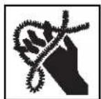
This symbol indicates the risk of hands, fingers or other body parts being caught, wrapped or crushed in the drain cleaning cable.

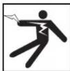
This symbol indicates the risk of electrical shock.

This symbol means always wear RIDGID drain cleaning mitts while operating drain cleaner.
This symbol indicates the risk of entanglement in a belt and pulley.
General Power Tool SafetyWarnings*
WARNING
Read all safety warnings, instructions, illustrations and specifications provided with this power tool. Failure to follow all instructions listed below may result in electric shock, fire, and/or serious injury.
SAVE ALL WARNING AND INSTRUCTIONS FOR FUTURE REFERENCE!
The term "power tool" in the warnings refers to your mains-operated (corded) power tool or battery-operated (cordless) power tool.
Work Area Safety
- Keep work area clean and well lit. Cluttered or dark areas invite accidents.
- Do not operate power tools in explosive atmospheres, such as in the presence of flammable liquids, gases, or dust. Power tools create sparks which may ignite the dust or fumes.
- Keep children and by-standers away while operating a power tool. Distractions can cause you to lose control.
Electrical Safety
- Power tool plugs must match the outlet. Never modify the plug in any way. Do not use any adapter plugs with earthed (grounded) power tools. Unmodified plugs and matching outlets will reduce risk of electric shock.
- Avoid body contact with earthed or grounded surfaces such as pipes, radiators, ranges and refrigerators. There is an increased risk of electrical shock if your body is earthed or grounded.
- Do not expose power tools to rain or wet conditions. Water entering a power tool will increase the risk of electrical shock.
- Do not abuse the cord. Never use the cord for carrying, pulling or unplugging the power tool. Keep cord away from heat, oil, sharp edges or moving parts. Damaged or entangled cords increase the risk of electric shock.
-
When operating a power tool outdoors, use an extension cord suitable for outdoor use. Use of a cord suitable for outdoor use reduces the risk of electric shock.
-
If operating a power tool in a damp location is unavoidable, use a ground fault circuit interrupter (GFCI) protected supply. Use of a GFCI reduces the risk of electric shock.
Personal Safety
- Stay alert, watch what you are doing and use common sense when operating a power tool. Do not use a power tool while you are tired or under the influence of drugs, alcohol, or medication. A moent of inattention while operating power tools may result in serious personal injury.
- Use personal protective equipment. Always wear eye protection. Protective equipment such as dust mask, non-skid safety shoes, hard hat, or hearing protection used for appropriate conditions will reduce personal injuries.
- Prevent unintentional starting. Ensure the switch is in the OFF position before connecting to power source and/or battery pack, picking up or carrying the tool. Carrying power tools with your finger on the switch or energizing power tools that have the switch ON invites accidents.
- Remove any adjusting key or wrench before turning the power tool ON. A wrench or a key left attached to a rotating part of the power tool may result in personal injury.
- Do not overreach. Keep proper footing and balance at all times. This enables better control of the power tool in unexpected situations.
- Dress properly. Do not wear loose clothing or jewelry. Keep your hair, and clothing away from moving parts. Loose clothes, jewelry, or long hair can be caught in moving parts.
- If devices are provided for the connection of dust extraction and collection facilities, ensure these are connected and properly used. Use of dust collection can reduce dust-related hazards.
- Do not let familiarity gained from frequent use of tools allow you to become complacent and ignore tool safety principles. A careless action can cause severe injury within a fraction of a second.
Power Tool Use and Care
- Do not force power tool. Use the correct power tool for your application. The correct power tool will do the job better and safer at the rate for which it is designed.
- Do not use power tool if the switch does not turn it
ON and OFF. Any power tool that cannot be controlled with the switch is dangerous and must be repaired.
- Disconnect the plug from the power source and/or the battery pack from the power tool before making any adjustments, changing accessories, or storing power tools. Such preventive safety measures reduce the risk of starting the power tool accidentally.
- Store idle power tools out of the reach of children and do not allow persons unfamiliar with the power tool or these instructions to operate the tool. Power tools are dangerous in the hands of untrained users.
- Maintain power tools and accessories. Check for misalignment or binding of moving parts, breakage of parts and any other condition that may affect the power tool's operation. If damaged, have the power tool repaired before use. Many accidents are caused by poorly maintained power tools.
- Keep cutting tools sharp and clean. Properly maintained cutting tools with sharp cutting edges are less likely to bind and are easier to control.
- Use the power tool, accessories and tool bits etc. in accordance with these instructions, taking into account the working conditions and the work to be performed. The use of the power tool for operations different from those intended could result in a hazardous situation.
- Keep handles and grasping surfaces dry, clean and free from oil and grease. Slippery handles and grasping surfaces do not allow for safe handling and control of the tool in unexpected situations.
Service
- Have your power tool serviced by a qualified repair person using only identical replacement parts. This will ensure that the safety of the power tool is maintained.
Specific Safety Information
WARNING
This section contains important safety information that is specific to this tool.
Read these precautions carefully before using the K-5208 Drain Cleaner to reduce the risk of electrical shock or other serious injury.
SAVE ALL WARNING AND INSTRUCTIONS FOR FUTURE REFERENCE!
Keep this manual with machine for use by the operator.
Drain Cleaner Safety
- Before using the tool, test the ground fault circuit interrupter (GFCI) provided with the power supply cord to insure it is operating correctly. A properly operating GFCI reduces the risk of electrical shock.
- Only use extension cords that are protected by a GFCI. The GFCI on the machine power cord will not prevent electrical shock from extension cords.
- Only grasp the rotating cable with gloves recommended by the manufacturer. Latex or loose fitting gloves or rags can become wrapped around the cable and may result in serious personal injury.
- Do not allow the cutter to stop turning while the cable is turning. This can overstress the cable and may cause twisting, kinking or breaking of the cable and may result in serious personal injury.
- One person must control both the cable and switch. If the cutter stops rotating, the operator must be able to turn the tool OFF to prevent the cable from twisting, kinking and breaking.
- Use latex or rubber gloves inside the gloves recommended by the manufacturer, goggles, face shields, protective clothing, and respirator when chemicals, bacteria or other toxic or infectious substances are suspected to be in a drain line. Drains may contain chemicals, bacteria and other substances that may cause burns, be toxic or infectious or may result in other serious personal injury.
- Practice good hygiene. Do not eat or smoke while handling or operating the tool. After handling or operating drain cleaning equipment, use hot, soapy water to wash hands and other body parts exposed to drain contents. This will help reduce the risk of health hazards due to exposure to toxic or infectious material.
- Only use the drain cleaner for the recommended drain sizes. Using the wrong size drain cleaner can lead to twisting, kinking or breaking of the cable and may result in personal injury.
Always use the rear guide hose while operating the tool and ensure the cable does not extend beyond the rear guide hose. This prevents the cable from whipping which may result in entanglement and personal injury. -
Keep mitt-covered hand on the cable whenever the machine is running. This provides better control of the cable and helps prevent twisting, kinking and breaking of the cable and may result in serious personal injury.
-
Position machine cable outlet within 2^ (0.6m) of the drain inlet or properly support exposed cable when the distance exceeds 2^ (0.6m) . Greater distances can cause control problems leading to twisting, kinking or breaking of the cable. Twisting, kinking or breaking cable may cause striking or crushing injuries.
- One person must control both the cable and the clutch. Do not lock clutch handle during operation. If the cutter stops rotating, the operator must be able to release the clutch to prevent twisting, kinking and breaking of the cable and reduce the risk of injury.
- Do not operate the machine in REV (reverse) rotation except as described in this manual. Operating in reverse can result in cable damage and is used to back the cable end out of blockages.
- Do not wear loose clothing or jewelry. Keep your hair and clothing away from moving parts. Loose clothing, jewelry or hair can be caught in moving parts.
- Do not operate this machine if operator or machine is standing in water. Operating machine while in water increases the risk of electrical shock.
- Do not engage drain cleaner clutch (rotate cable) while any part of the cable is in the cable carrier. This may cause striking or crushing injuries.
- Do not use if there is the risk of contact with other utilities (such as natural gas or electric) during operation. Visual inspection of the drain with a camera is a good practice. Crossbores, improperly placed utilities and damaged drains could allow the cutter to contact and damage the utility. This could cause electrical shock, gas leaks, fire, explosion or other serious damage or injury.
- Read and understand these instructions and the instructions and warnings for all equipment and materials being used before operating this tool to reduce the risk of serious personal injury.
RIDGID Contact Information
If you have any question concerning this RIDGI product:
- Contact your local RIDGID® distributor.
- Visit RIDGID.com to find your local RIDGID contact point.
- Contact Ridge Tool Technical Service Department at rtctechservices@emerson.com, or in the U.S. and Cana da call (800) 519-3456.
Description
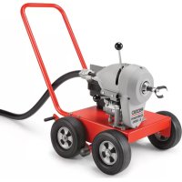
The RIDGID K-5208 Drain Cleaning machine is designed
to clean 2^ (50mm) to 8^ (200mm) drain lines and up to 200 feet (61m) in length depending on size of cable. Applications include laterals, main lines, commercial lines.
A FOR/O-OFF/REV switch controls cable rotation and provides ON/O-OFF control of the motor. An integral Ground Fault Circuit Interruption (GFCI) is built into the line cord.
The K-5208 is designed to use 18 (22mm) and 114 (32mm) diameter sectional-type cable, having a quick-change coupling system for connecting and disconnecting cables and tools. The cable is manually fed in and out of the drain and rotates at a speed of 700 RPM.
The rotation of the cable is controlled by a clutch lever handle. The cable stops instantly when the clutch lever handle is released.
A cable decoupler is provided for disconnecting the cables and tools.
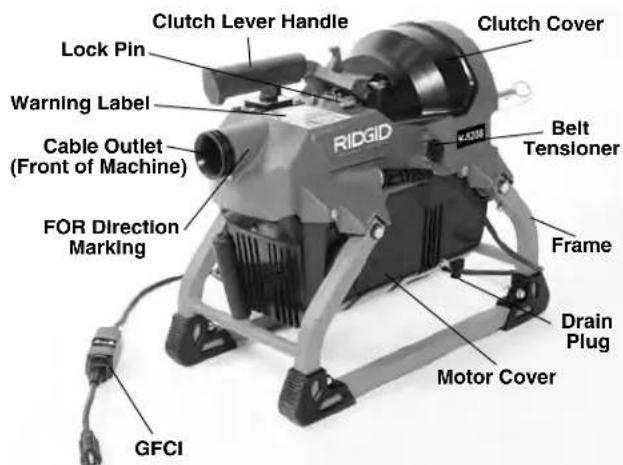
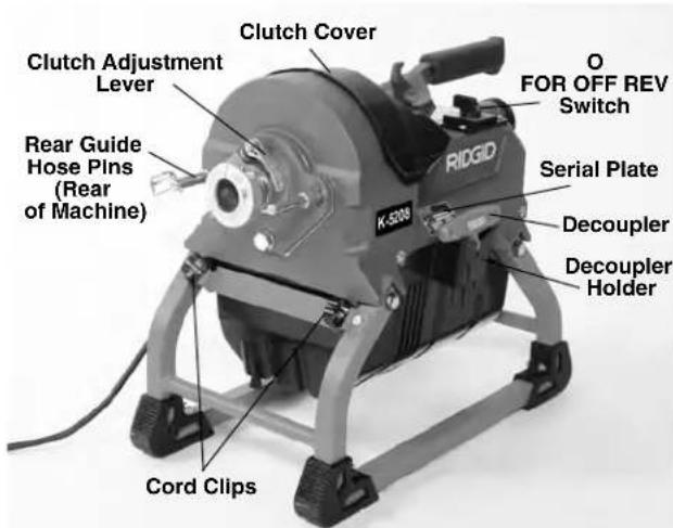
Figure 1 - K-5208 Drain Cleaning Machine
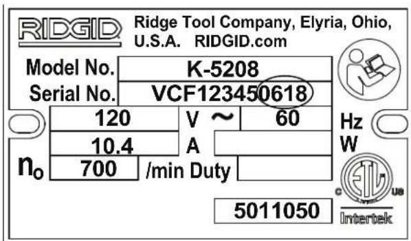
Figure 2 - Machine Serial Number - The last 4 digits indicate the month and year of the manufacture. (06 = month, 18 = year).
Specifications
Drain Line Capacity....2-8" (50 to 200 mm) See Chart Cable .......7/8" and 114 Cable
| Cable Size Drain Size Reach | ||
| 7/2" (22 mm) | 2" to 4" Up to 175' (53 m) (50 to 100 mm) | |
| C-10 | 2" to 4" | |
| C-10 IC | (50 to 100 mm) Drains | |
| 2" to 4" | ||
| (50 to 100 mm) Drains | ||
| 1¼" (32 mm) | 3" to 8" Up to 200' (61 m) (75 to 200 mm) | |
| C-11 | 3" to 8" (75 to 200 mm) | All Purpose, ¾" (10 mm) pitch |
| C-11 PC | Drains, 4" (100 mm) Traps | C-11 w/Plastic Core |
| C-12 | 4" (100 mm) Traps | Extra Heavy Duty |
| 4" to 8" (100 to 200 mm) Drains, Not for 4" (100 mm) traps | ½" (10 mm) pitch | |
| C-14 | 3" to 8" (75 to 200 mm) Drains, Not for 4" (100 mm) traps | Heavy Duty, ½" (13 mm) Pitch |
| C-15 | 3" to 6" (75 to 150 mm), Good for traps | Extra Flexible, ½" (13 mm) Pitch |
All Cables come in 15^ (4.5m) lengths
Motor Type ............Induction, 3/4 HP Nominal Output
Motor Ratings
| Volts (V) | 120 | 220-240 | 110 |
| Frequency (Hz) | 60 | 50/60 | 50 |
| Current Draw (A) | 10.4 | 5.2 | 10.4 |
| Power (W) | 1248 | 1248 | 1144 |
| No Load Speed (ηo) | 700 | 585/700 | 585 |
Refer to on product serial plate for information specific to unit.
Controls FOR/O-OFF/REV Switch Clutch lever handle
Operating
Temperature. -20° F to 120° F (-29°C to 49°C)
Storage Temperature ....-20° F to 140° F (-29°C to 60°C)
Dimension L × W × H .........21.2" × 11.6" × 18.2"
(540× 295× 465mm)
Handle in down position
Drain Cleaner Weight ....54 lb. (24 kg)
Sound Pressure (_A)^* ....78.3 dB(A), K = 3
Sound Power (L_w)^* .83.5 dB(A), K=3
-
Sound measurements are measured in accordance with a standardized test per Standard EN 62841-1.
-
Sound emissions may vary due to your location and specific use of these tools.
- Daily exposure levels for sound need to be evaluated for each application and appropriate safety measures taken when needed. Evaluation of exposure levels should consider the time a tool is switched off and not in use. This may significantly reduce the exposure level over the total working period.
Standard Equipment
All K-5208 Drain Cleaning machines come with one RIDGID Drain Cleaning Mitt. Refer to the RIDGID catalog for details on equipment supplied with specific drain cleaner catalog numbers.
NOTICE This machine is made to clean drains. If properly used it will not damage a drain that is in good condition and properly designed, constructed and maintained. If the drain is in poor condition, or has not been properly designed, constructed and maintained, the drain cleaning process may not be effective or could cause damage to the drain. The best way to determine the condition of a drain before cleaning is through visual inspection with a camera. Improper use of this drain cleaner can damage the drain cleaner and the drain. This machine may not clear all blockages.
Pre-Operation Inspection
WARNING

Before each use, inspect your drain cleaning machine and correct any problems to reduce the risk of serious injury from electric shock, twisted or bro ken cables, chemical burns, infections and other causes and prevent drain cleaner damage.
Always wear safety glasses, and other appropriate protective equipment when inspecting your drain cleaner.
- Inspect the RIDGID drain cleaning mitts (Figure 3). Make sure they are in good condition with no holes, tears or loose sections that could be caught in the rotating cable. It is important not to wear improper or
damaged mitts. The mitts protect your hands from the rotating cable and drain contents. If the mitts are not RIDGID drain cleaning mitts or are damaged or worn out, do not use machine until RIDGID drain cleaning mitts are available. Wear latex or rubber gloves inside the mitt to protect against drain conFig tents.
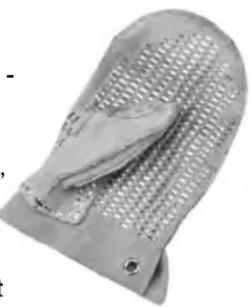
gure 3 - RIDGID Drain Cleaning Mitt
- Make sure that the drain cleaning machine is unplugged and inspect the power cord, Ground Fault Circuit Interrupter (GFCI) and plug for damage. If the plug has been modified, or if the cord is damaged, to avoid electrical shock, do not use the machine until the cord has been replaced by a qualified repair person.
- Clean the drain cleaner, including handles and controls. This aids inspection and helps prevent the machine or control from slipping from your grip. Clean and maintain the machine per the maintenance instructions.
-
Inspect the drain cleaning machine for:
-
Proper assembly and completeness.
- Broken, worn, missing, misaligned or binding parts.
- Presence and readability of the warning label (see Figure 1).
- Smooth and free movement of the clutch lever handle. Slightly depress the clutch lever handle and turn the lock pin clockwise (Figure 4) to release. The clutch lever handle is spring loaded and will be biased up when released.

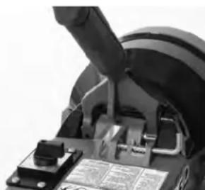
Figure 4 - Releasing the Clutch Handle
- Confirm that the clutch and motor covers are securely fastened to the drain cleaner and the motor vents are clear. Do not operate without the covers in place.
- Any other condition which may prevent safe and normal operation.
If any problems are found, do not use the drain cleaner until the problems have been repaired.
-
Clean any debris from the cable and cutters. Inspect cable for wear and damage. Inspect for:
-
Obvious flats worn into the outside of the cable (cable is made from round wire and profile should be round).
- Multiple or excessively large kinks (slight kinks up to 15 degrees can be straightened).
- Uneven space between cable coils indicating that the cable has been deformed by stretching, kinking, or running in reverse (REV).
- Excessive corrosion from storing wet or exposure to drain chemicals.
All of these forms of wear and damage weaken the cable and make cable twisting, kinking or breaking more likely during use. Inspect the cutters. Replace worn and damaged cable and cutters before using drain cleaner.
Inspect the cable couplings for wear and damage.
Confirm that coupling plunger pins move freely and fully extend for positive retention. If needed, lubricate with a light oil.
- Inspect and maintain any other equipment being used per its instructions to make sure it is functioning properly.
- Make sure that the FOR/O-OFF/REV switch is set to the O-OFF position.
- With dry hands, plug cord into properly grounded outlet. Test the GFCI provided in the electrical cord to ensure that it is operating correctly. Depress the GFCI TEST button -the machine should not operate. Depress the RESET button - the machine should operate. If GFCI is not functioning properly, unplug the cord and do not use the drain cleaning machine until the GFCI has been repaired.
- With the inspection complete, with dry hands, unplug the machine.
Machine and Work Area Set-Up
WARNING

Set up the drain cleaning machine and work area according to these procedures to reduce the risk of injury from electric shock, fire, machine tipping, twisted or broken cables, chemical burns, infec
tions and other causes, and prevent drain cleaner damage.
Always wear safety glasses and other appropriate protective equipment when setting up your drain cleaner.
-
Check work area for:
-
Adequate lighting.
- Flammable liquids, vapors or dust that may ignite. If present, do not work in area until sources have been identified and corrected. The drain cleaner is not explosion proof and can cause sparks.
- Clear, level, stable, dry location for all equipment and operator. Do not use machine while standing in water. If needed, remove water from the work area.
- Properly grounded electrical outlet of the correct voltage. Check machine serial plate for required voltage. A three-prong or GFCI outlet may not be properly grounded. If in doubt, have outlet inspected by a licensed electrician.
-
Clear path to electrical outlet that does not contain any potential sources of damage for the power cord.
-
Inspect the drain to be cleaned. If possible, determine the access point(s) to the drain, the size(s) and length(s) of the drain, distance to tanks or mainlines, the nature of the blockage, presence of drain cleaning chemicals or other chemicals, etc. If chemicals are present in the drain, it is important to understand the specific safety measures required to work around those chemicals. Contact the chemical manufacturer for required information. Confirm no other utilities are present in the drain or area to reduce the risk of damage. Visual inspection of the drain with a camera is a good practice.
If needed, remove fixture (water closet, etc.) to allow access to drain. Do not feed the cable through a fixture. This could damage the drain cleaner and the fixture.
- Determine the correct equipment for the application. See Specifications.
Drain cleaners for other applications can be found by consulting the RIDGID Catalog, online at RIDGID.com
- Make sure all equipment has been properly inspected.
- If needed, adjust the machine clutch for the size of cable to be used (see Jaw/Clutch Adjustment).
- If needed, place protective covers in the work area. The drain cleaning process can be messy.
- Position the drain cleaning machine so that the cable outlet is within 2 feet (0.6m) of the drain access.
Greater distances from the drain access increases the risk of the cable twisting or kinking. If the machine cannot be placed with the cable outlet within 2^ (0.6m) of the drain access, extend the drain access with similar sized pipe and fittings (see Figure 5). Improper cable support can allow the cable to kink and twist and can damage the cable or injure the operator.
- Unlock the clutch lever handle (Figure 4).
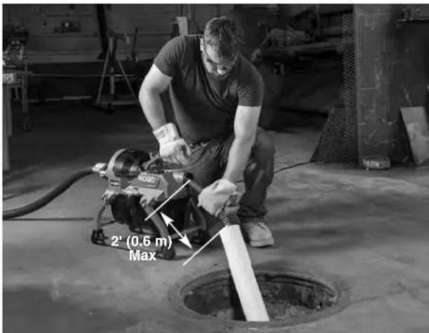
Figure 5 - Example of Extending Drain to within 2^ (0.6m) of Machine Cable Outlet
- Attach the rear guide hose to the machine (Figure 6) by sliding the bracket over the posts. Do not use machine without rear guide hose attached. The rear guide hose improves cleanliness and reduces the risk of cable whipping and entanglement. A lanyard mounted pin is supplied to retain the guide hose to the machine.
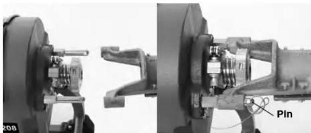
Figure 6 - Rear Guide Hose Attachment
- Fully remove a section of cable from the carrier and insert female end of the cable into cable outlet of the machine (Figure 7). Push the cable through machine and guide hose until approximately one foot (0.3m) remains out the front of the machine. Disconnect the cable section from the cable sections still in the carrier. Do not use the drain cleaner to rotate cable in carrier, this may cause striking or crushing injuries.
Cable sections can be removed from the cable carrier one at a time as used, or all at once, as the situation requires. If using the drum style cable carrier, placing the cable carrier near the drain opening and the machine cable outlet allows convenient access for loading and unloading of cable sections. See Figure 7.
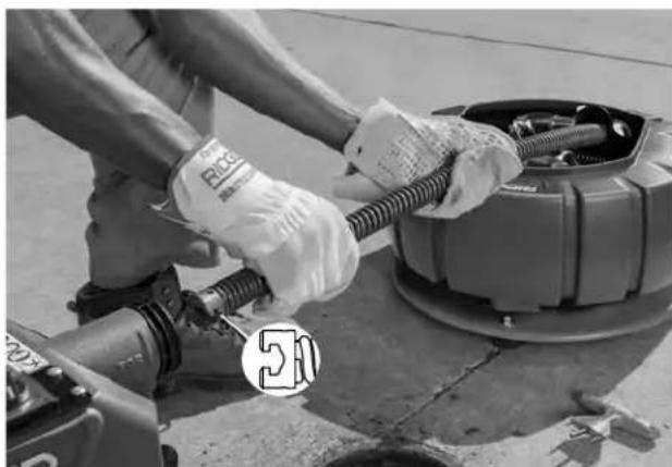
Figure 7 - Inserting Cable Into Front Of Machine
- Select proper tool for the conditions. If the nature of the obstruction is unknown, it is good practice to use a straight auger to explore the obstruction and retrieve a piece of the obstruction for inspection.
Once the nature of the obstruction is known, an appropriate tool can be selected for the application. A good rule of thumb is to start by running the smallest available tool through the blockage to allow the backed-up water to start flowing and carry away the debris and cuttings as the drain is cleaned. Once the drain is open and flowing, other tools appropriate for the blockage can be used. Generally, the largest tool used should be no bigger than the inside diameter of the drain minus one inch.
Proper tool selection depends on the specific circumstances of each job and is left to the user's judgement. A variety of other tools are available and are listed in the Optional Equipment section of this manual. Other information on tools can be found in the RIDGID Catalog.
-
Securely install tool on the end of the cable (see Figure 8). If the connection is not secure, the cutting tool may fall off in use. As the cutting tool is installed make sure that the spring-loaded plunger in coupling on the end of cable moves freely to retain the tool. If the pin sticks in the retracted position, the cutting tool may fall off in use.
-
Insert tool and cable end at least 1^ (0.3m) into drain.
Connecting/Disconnecting Sectional Cable Couplings
Keep couplings clean and lubricated. Plunger pin must move freely and fully extend to secure connection.
Connecting
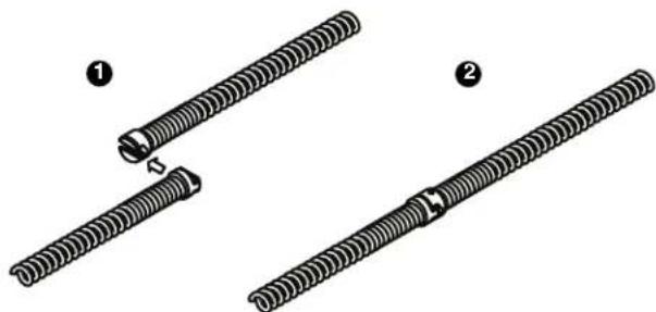
1. Slide the couplings together.
2. Confirm connection is secure. (Plunger pin fully extended.)
Disconnecting - Using Pin Key
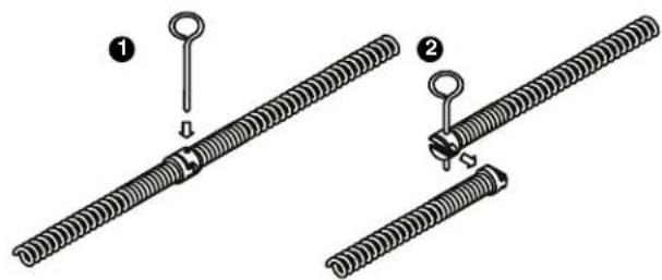
1. Fully insert pin key (rotate, if needed) to depress the plunger pin.
2. Slide couplings apart
Disconnecting - Using Trident Sectional Cable Decoupler (Cat. # 61718)
1. Fully insert decoupler (tapered end) to depress the plunger pin. couplings apart.
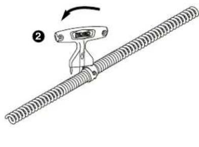
2. Rotate decoupler to contact other coupling. 3. Continue rotating decoupler to slide
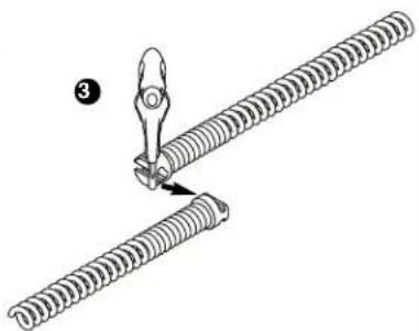
Figure 8 - Coupling and Uncoupling
- Evaluate the work area and determine if any barriers are needed to keep bystanders away from the drain cleaner and work area. The drain cleaning process can be messy and bystanders can distract the operator.
- Position the machine for easy accessibility. You must be able to hold and control the cable and clutch lever handle, load and unload cable sections and reach the FOR/O-OFF/REV switch.
- Confirm that the FOR/O-OFF/REV switch is in the O-OFF position.
- Run the cord along the clear path. With dry hands, plug the drain cleaner into a properly grounded outlet. Some GFCIs may need to be reset every time they are plugged in. Reset GFCI if needed. Keep all connections dry and off the ground. If the power cord is not long enough, use an extension cord that:
Is in good condition.
- Has a plug similar to that supplied on the drain cleaner.
Is rated for outdoor use and contains a W or W-A in the cord designation (i.e. SOW), or complies with H05VV-F, H05RN-F types or IEC type design (60227 IEC 53, 60245 IEC 57). - Has sufficient wire size. For extension cords up to 50' (15,2 m) long use 16 AWG (1,5m) or heavier. For extension cords 50' - 100' (15,2 m - 30,5 m) long use 14 AWG (2,5mm) or heavier.
When using an extension cord, the GFCI on the drain cleaner does not protect the extension cord. If the outlet is not GFCI protected, it is advisable to use a plug in type GFCI between the outlet and the extension cord to reduce the risk of shock if there is a fault in the extension cord.
Operating Instructions
WARNING


Always wear eye protection to reduce the risk of eye injury.
Always wear RIDGID drain cleaning mitts in good condition. Latex or loose fitting mitts or rags can become wrapped around the cable and may result in serious personal injury. Only wear latex or rubber gloves under drain cleaning mitts. Do not use damaged drain cleaning mitts.
Always use appropriate personal protective equipment while handling and using drain cleaning equipment. Drains may contain chemicals, bacteria and other substances that may be toxic, infectious, cause burns or other issues. Appropriate personal protective equipment always includes safety glasses and RIDGID drain cleaning mitts, and may include equipment such as latex or rubber gloves, face shields, goggles, protective clothing, respirators and steel-toed footwear.
Do not allow the cutter to stop turning while the machine is running. This can overstress the cable and may cause twisting, kinking or breaking of the cable. Twisting, kinking or breaking cable may cause striking or crushing injuries.
Keep mitt covered hand on the cable whenever the machine is running. This provides better control of the cable and helps prevent twisting, kinking and breaking of the cable. Twisting, kinking or breaking cable may cause striking or crushing injuries.
Position the machine so that cable outlet is within two feet (0.6m) of the drain inlet or properly support exposed cable when the distance exceeds two feet. Greater distances can cause control problems leading to twisting, kinking or breaking of the cable. Twisting, kinking or breaking cable may cause striking or crushing injuries.
One person must control both the cable and the clutch. Do not lock clutch handle during operation. If the cutter stops rotating, the operator must be able to release the clutch to prevent twisting, kinking and breaking of the cable and reduce the risk of injury.
Follow operating instructions to reduce the risk of injury from twisted or broken cables, cable ends whipping around, machine tipping, chemical burns, infections and other causes.
-
Make sure that machine and work area is properly set up and that the work area is free of bystanders and other distractions.
-
Pull cable out of machine and feed into drain. At
least one foot (0.3m) of cable must be in drain so that the end of the cable will not come out of the drain and whip around when the machine is started.
Directly route the cable from machine cable outlet to the drain opening, minimizing exposed cable and changes in direction. Do not tightly bend the cable - this can increase the risk of twisting or breaking.
-
Assume a proper operating position to help maintain control of the cable and machine (see Figure 9):
-
Be sure you can quickly release the clutch lever handle.
-
Your mitted hand must be on the cable to control and support it.
-
Be sure that you have good balance, do not have to overreach, and cannot fall on drain cleaning machine, drain or other hazards.
-
You must be able to reach the FOR/O-OFF/REV switch.
-
Can reach additional cable sections.
This operating position will help to maintain control of the cable and machine.
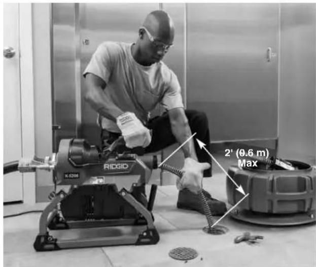
Figure 9 - In Operating Position
Feeding The Cable Into The Drain
-
Confirm that at least one foot of cable is in the drain.
-
Grasp near the center of exposed cable with mitted hand and pull 6^ to 12^ (150 to 300~mm ) of cable out of the machine so that there is a slight bow in the cable. Mitt covered hand must grasp cable to control and support the cable. Improper cable support can allow the cable to kink or twist and can damage the cable or injure the operator. Make sure that the cable outlet of drain cleaner is within 2^ ( 0.6m ) of the drain opening.
-
Move the FOR/O-OFF/REV switch to FOR (Forward) position. The motor will start but the cable will not rotate. FOR/O-OFF/REV refers to the cable rotation and not to the direction of cable movement.
-
With mitted hand grasping cable, use the other hand (use a drain cleaning glove or mitt on the clutch lever handle) to operate the clutch lever handle. Move the lever down quickly and definitely to engage clutch and turn cable (Figure 11A). A slow or gradual clutch engagement causes excessive jaw set wear. The person controlling the cable must also control the clutch lever handle. Do not operate the drain cleaner with one person controlling the cable and another person controlling the clutch lever handle. This can lead to twisting, kinking and breaking of the cable. At any time, move the clutch lever handle up or release to stop cable rotation.
Confirm that the cable is rotating in the proper direction. In FOR, the machine should rotate counterclockwise when viewed from the front of the machine, as shown in the machine casting (Figure 10). If the rotation is not correct, do not use the machine until it has been repaired. Do not rotate the cable in reverse except as specifically described in these instructions. Running the drain cleaner in REV can damage the cable.
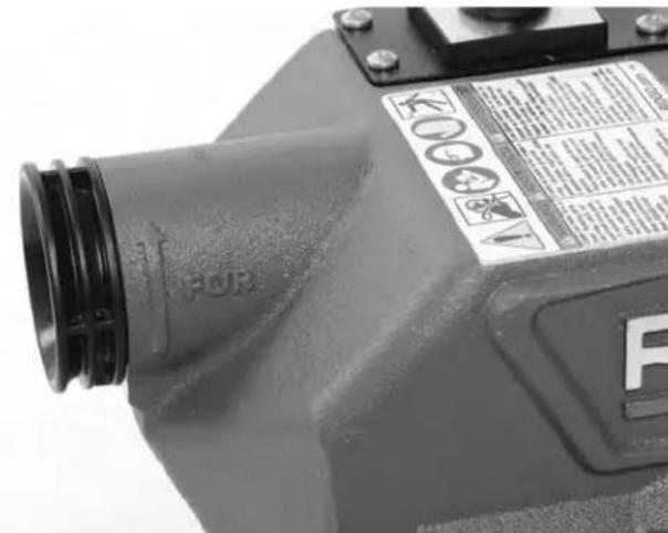
Figure 10-FOR Machine Rotation Marking
- Feed the rotating cable into the drain. The rotating cable will work its way into the drain as you push on the cable with your mitted hand. Do not allow cable to build up outside the drain, bow or curve. This can allow the cable to twist, kink or break.
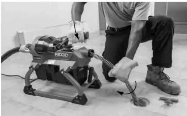
Figure 11A - Clutch Engaged, Cable Rotating, Feeding Cable Into Drain
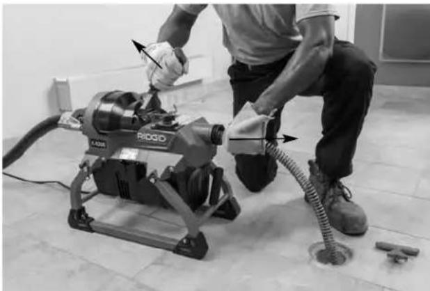
Figure 11B - Clutch released, Cable Not Rotating, Pulling Cable From Machine
- When the cable has been fed into the drain opening, release clutch lever handle and pull 6'' to 12'' (150 to 300mm more cable from the machine (Figure 11B).
- Repeat steps 4-6 the until the clutch is gripping near the end of the cable section.
- To add a section of cable:
a. Release the clutch lever handle and move the FOR/O-OFF/REV switch to O-OFF position.
b. If needed, secure the cable to prevent loss down the drain, such as when working in vent. See Figure 12 for one method to secure the cable.
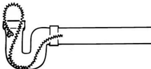
Figure 12 - Looping Cable In Line to Secure
c. Insert the female end of a cable section into front of machine (Figure 7). Push the cable through machine and guide hose until approximately one foot (0.3m) remains out the front of the machine. Do not load more than one section of cable at a time. Cable section must be completely removed from the cable carrier before operating machine.
d. Securely couple cable sections together (Figure 8) and insert any excess cable into machine. Resume operation, repeating steps 4-6.
Passing Through Traps Or Other Transitions
If it is hard to get the cable through a trap or other fitting, the following methods or combination of methods can be used.
a. Sharp downward thrusts on the cable, both with and without the cable rotating, can help the cable through a trap.
b. With the clutch lever handle released, rotating the cable by hand can change the orientation of the cutter to allow it to more easily negotiate the fitting.
c. Run the drain cleaner in REV rotation for several seconds while pushing down on the cable. Only do this long enough to get the cable started through the trap. Running the cable in reverse can damage the cable.
If these options do not work, consider using a smaller diameter or more flexible cable, or a different RIDGID drain cleaner.
Cleaning The Drain
Always keep at least one hand on the cable. Pay attention how the cable feels in your hand and watch the cable rotation.
As you feed the cable into the drain, you may feel and see the cable slow down and start to load or wind up (this may feel like the cable is starting to twist or squirm). See Figure 13. This may be a transition in the drain line (trap, elbow, etc.), build up in the drain (grease, etc.), or the actual blockage. Feed the cable slowly and carefully. Do not let cable build up outside drain. This can cause the cable to twist, kink or break.
Pay attention to the amount of cable that has been fed into the drain. The number of sections of cable in use gives an indication of total cable length. Feeding cable into a larger drain line or similar transition may cause the cable to kink or knot and prevent removal from the drain. Minimize the amount of cable fed into the transition to prevent problems.
Cable is not attached inside the machine. When ap
proaching end of cable section, keep hand securely on the cable to avoid losing it down the drain.
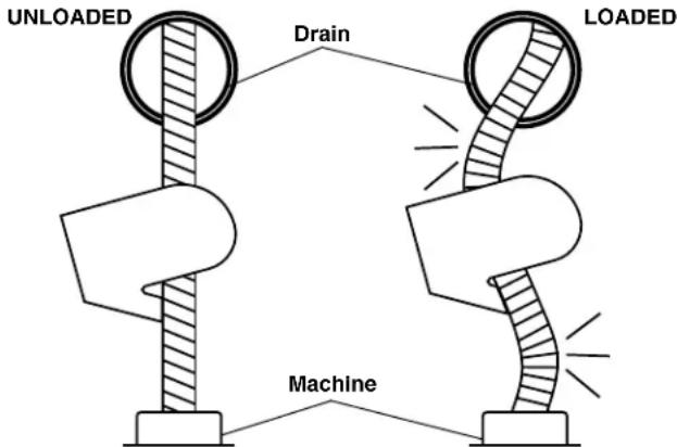
Figure 13 - Cable Shape When Unloaded, Loaded
Working The Blockage
If the end of cable stops turning, it is no longer cleaning the drain. If the cable end becomes lodged in the blockage and power is maintained to the drain cleaner, the cable will start to wind up or buildup outside the drain. Having a hand on the cable allows you to feel this wind up (this may feel like the cable is starting to twist or squirm) and control the cable. As you feel the cable wind up or if the cable end stops turning, immediately release the clutch lever handle and pull back on cable to free the cable end from blockage. Do not keep the cable rotating if the cable end is stuck in a blockage. If the cable end stops turning and the clutch is engaged, the cable can twist, kink or break.
Once the cable end is free of the blockage and the cable end is turning again, you can slowly feed the rotating cable end back into the blockage. Let the spinning cable end "dwell" in the blockage to completely break it up. Do not try to force the cable end through the blockage. Work the cable end in this manner until it has moved completely past the blockage (or blockages), and the drain is flowing.
While working the blockage, the cable end may become clogged with debris and cuttings from the blockage. This can prevent further progress. The cable needs to be retrieved from the drain and the debris removed. See section on "Retrieving the Cable".
If the cable end continues to get hung up in the blockage, a different tool may be needed.
Handling A Stuck Tool/Cable End
If the cable end stops turning and the cable cannot be pulled back from the blockage, release the clutch lever handle. Maintain a firm grip on the cable. The cable may turn backwards until the energy stored in the cable is
relieved. Do not remove hand from the cable until the tension is released. Place FOR/O-OFF/REV switch in the O-OFF position.
Freeing A Stuck Tool
If the cable is stuck in the blockage, with the FOR/O-OFF/REV switch in the O-OFF position, try pulling the cable loose from the blockage. If the tool will not come free, place FOR/O-OFF/REV switch in the REV position. Press the clutch lever handle for several seconds until cable is free of the blockage. Do not operate the machine in the REV position any longer than required to free the cable end from the blockage or cable damage can occur. Place the FOR/O-OFF/REV switch in the FOR position and continue cleaning the drain.
Retrieving The Cable
- Once the drain is open, if possible start a flow of water down the drain to flush the debris out of the line and help clean the cable as it is retrieved. This can be done by turning on a faucet in the system or other methods. Pay attention to the water level, as the drain could plug again.
- The FOR/O-OFF/REV switch should be in the FOR position - do not retrieve the cable with the switch in the REV position, this can damage the cable. As with feeding the cable into the drain, cables can be caught while being retrieved.
- Engage the clutch lever handle and pull 6^ to 12" (150 to 300mm ) cable out of drain (Figure 14A).
- Release the clutch lever handle and feed excess cable into the machine (Figure14B).
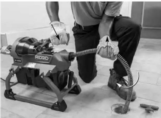
Figure 14A - Clutch Engaged, Cable Rotating, Pulling Cable Out of Drain
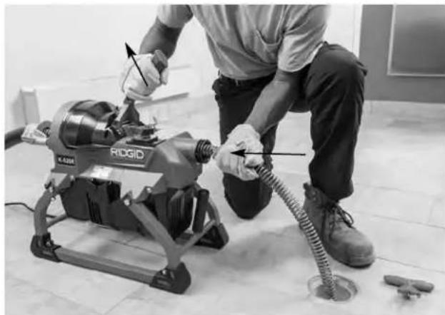
Figure 14B - Clutch Released, Cable Not Rotating, Feeding Cable Into Machine
- Repeat process until the cable coupling (joint) has moved past the clutch.
a. Release the clutch lever handle, place the FOR/O-OFF/REV switch in the O-OFF position.
b. Uncouple the cable sections (see Figure 8). If needed, secure the cable to prevent loss down the drain.
c. Remove cable section from drain cleaner and place in cable carrier if desired. Do not operate machine with more than one cable section in the guide hose, or with cable rotating on the ground. Rotating cable lying on the ground can move around the area, damage the surroundings, and cause injury.
- Reinsert the cable into the machine, place the FOR/O-OFF/REV switch in the FOR position and continue retrieving the cable until the tool is just inside the drain opening.
- Release clutch lever handle. Do not pull the end of the cable from the drain while the cable is rotating. The cable can whip around and cause serious injury.
- Place the FOR/O-OFF/REV switch in the O-OFF position and pull the remaining cable from the drain. If needed, change the tool and continue cleaning the drain. Several passes through a drain are recommended for complete cleaning.
- Remove the tool from the cable. Remove cable from the drain cleaner.
- With dry hands unplug the machine.
Draining The Machine
Place a suitable container under the drain plug (Figure 1). Pull drain plug loose (it is retained by a lanyard) and allow to drain. Replace plug when finished.
Preparing For Transport
Remove the guide hose from the machine. Latch the clutch lever handle in the down position. Wrap cord around the clutch lever handle and clip the GFCI in place. Secure as shown in Figure 15. Firmly insert Decoupler in holder to secure. When loading cable sections into a cable carrier, connecting the sections makes loading and unloading easier. One transport method shown in Figure 16.

Figure 15 - Cord In Transport Position

Figure 16 - Transport
Storage
WARNING The drain cleaner must be kept dry and indoors or well covered if kept outdoors. Store the machine in a locked area that is out of reach of children and people unfamiliar with drain cleaners. This machine can cause serious injury in the hands of untrained users.
Maintenance Instructions
WARNING
FOR/O-OFF/REV switch should be O-OFF and machine unplugged before performing any maintenance. Always wear safety glasses and other appropriate protective equipment when performing any maintenance.
Cleaning
A mild detergent or antibacterial solution can be used if desired. Do not use solvents, abrasives or other harsh cleaning agents.
Machine - Use a damp, soft cloth to wipe off the machine. Do not submerge or flush the machine with water. Do not allow water to enter motor or other electrical components. Make sure unit is completely dry before plugging in and using.
Monthly, follow the "Changing Clutch Jaw Assembly" directions and inspect the clutch jaws. Clean or replace if necessary.
Cables- Remove debris from cable and flush cable with water after every use to prevent damaging effects of sediment and drain cleaning compounds. Allow to dry to reduce cable corrosion.
Guide Hose - Flush with water and drain. Use a damp, soft cloth to wipe off. Allow to dry to reduce corrosion.
Lubrication
Machine - machine is lubricated for life and requires no further lubrication.
Cables - lubricate coupling plunger pins with light machine oil.
Guide Hose - Pull a lightly oiled towel through the dry guide hose to keep it flexible.
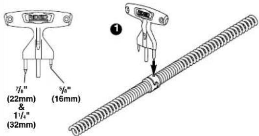
Jaw/Clutch Adjustment
When clutch lever handle is in up position (released), if the cable will not slide through the machine, the jaws are set too small. If the cable does not turn when the clutch lever handle is engaged, the jaws are set too large.
When changing between 1^1/4 (32mm) and 7^1/8 (22mm) cable, the clutch must be adjusted.
-
Open quick release on collar (Figure 17).
-
Turn adjustment knob as needed.
a. Turn counter-clockwise (viewed from the rear) for jaw set larger.
b. Turn clockwise for jaw set smaller.
c. When changing from 1^1 / 4^n (32mm) to 7 / 8^ (22mm) cable, turn the adjustment knob approximately'A turns clockwise.
-
Insert cable through the machine. Press the clutch lever handle DOWN and check engagement of jaws with cable. Adjust as needed.
-
Close quick release. Confirm that the quick release is secure (adjustment knob cannot be turned). If needed adjust the collar quick release by tightening or loosening the nut.
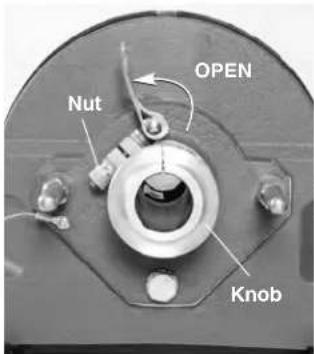
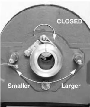
Figure 17 - Jaw Set Adjustment
Changing Clutch Jaw Assembly
If the clutch cannot be adjusted to suitably grip the cable, the clutch jaw assembly is worn and needs to be changed.
- Using the "Jaw/Clutch Adjustment" procedure, count the number of turns of the adjustment knob to fully open the jaw set, until the adjustment shaft will not turn any further.
- Loosen the two screws in the clutch cover (they are retained and will not come out) and remove the cover. Unlock the clutch lever handle and allow to fully open.
- Remove the clutch jaw assembly.
- Hold new clutch jaws assembly (Catalog #61998) in alignment with the clutch cones. Engage the clutch handle and lock in closed position (Figure 18).
- Reinstall the clutch cover and securely tighten the screws. Do not operate the machine without the cover installed.
- Use the "Jaw/Clutch Adjustment" procedure and adjust the clutch. Do not lubricate the clutch.
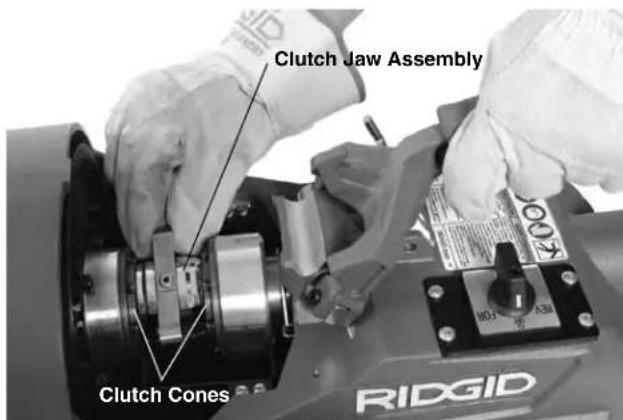
Figure 18 - Clutch Jaw Installation
Changing Belt
- Using the "Changing Clutch Jaw Assembly" procedure, remove the clutch jaw assembly from the machine.
- Remove the drip tray screws and remove the drip tray (Figure 19).
- Loosen belt tensioner. Using a 13mm wrench, loosen the jam nut 2-3 turns. Loosen knob 10 turns.
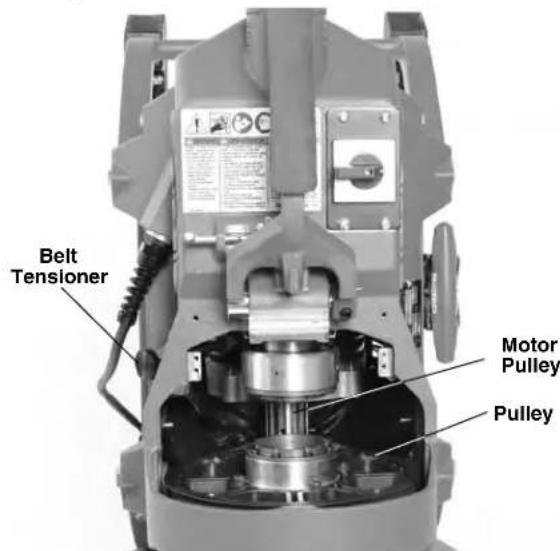
Figure 19 - Machine Standing on Back, Drip Tray Removed
- Stand machine on back end.
- Remove belt from pulleys.
- Confirm that motor swings freely on the motor pivots
- Reverse procedure to install belt.
-
Tension the belt following the "Belt Tensioning" procedure.
-
Reassemble unit, making sure that all covers are securely in place.
Belt Tensioning
-
Every three months or as needed, check the belt tension.
-
Loosen belt tensioner. Using a 13mm wrench, loosen the jam nut 2-3 turns. Loosen knob one turn (Figure 20).
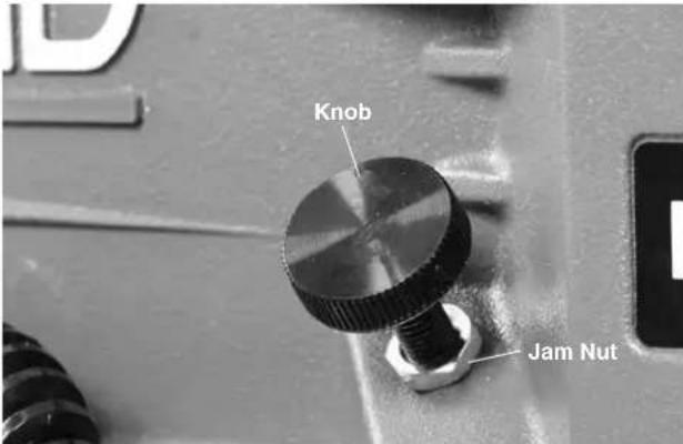
Figure 20-Belt Tensioner
- Tensioning the belt. The weight of the motor sufficiently tensions the belt. Tighten the belt tensioner knob until it touches the motor housing plus 1/4 turn. Run the jam nut down against the machine housing. While holding the knob stationary, tighten the jam nut to lock the belt tensioner in place.
Changing Front Nose Piece
The front nose piece is a wear component. If worn, change by driving out retaining pin (Figure 21) and pulling the nose piece from the housing. The new nose piece (catalog #62003 - this contains the nose piece, the retaining pin, and the o-ring) can only be fully inserted in one orientation. Install retaining pin.
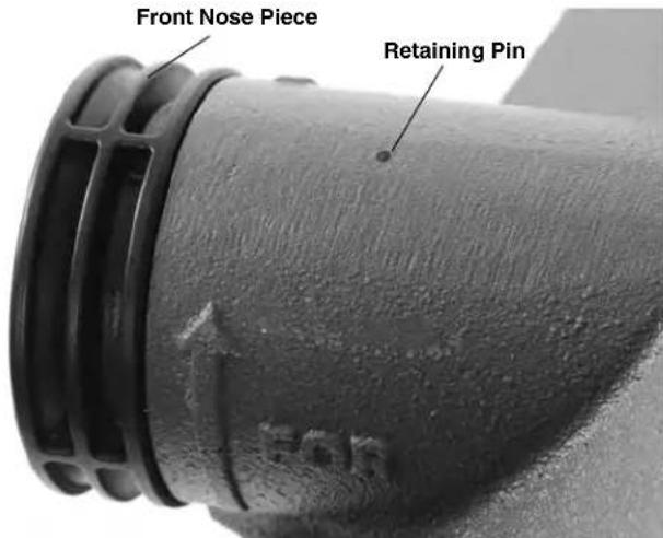
Figure 21 - Front Nose Piece Change Out
Motor Thermal Overload
The motor is equipped with a thermal overload that turns OFF the motor if it gets too hot. To reset the thermal overload, unplug machine, turn ON/O-OFF/REV switch to the O-OFF position and allow the motor to cool for 15 minutes. Use a thin, non-conductive probe to reach through the opening in the motor cover (Figure 22) to press the reset button. If motor does not start or the thermal overload continually trips during normal operation, the machine should be taken to a RIDGID Independent Service Center.
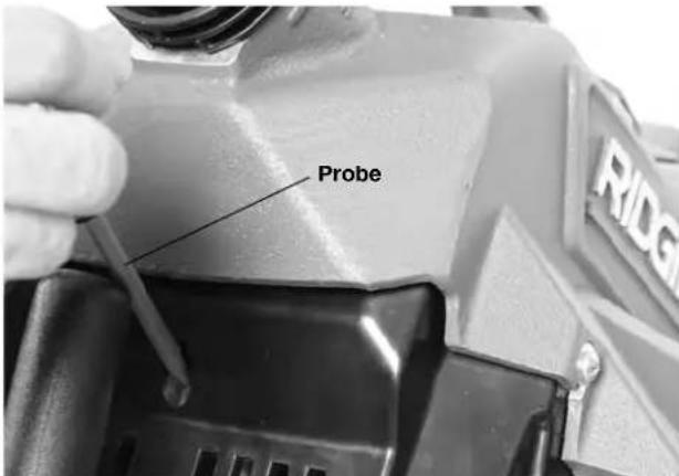
Figure 22 - Motor Reset Button
Troubleshooting
| PROBLEM POSSIBLE REASONS SOLUTION | ||
| Cable kinking or breaking. | Cable is being forced. | Do Not Force Cable! Let the cutter do the work. |
| Cable used in incorrect pipe diameter. | Use correct cable for pipe size. | |
| Motor switched to reverse. | Use reverse only if cable gets caught in pipe. | |
| Cable exposed to acid. | Clean cables routinely. | |
| Cable worn out. | If cable is worn, replace it. | |
| Cable not properly supported. | Support cable properly, see instructions. | |
| Cable turns in one direc-tion but not the other. | Faulty FOR/O-OFF/REV switch. | Have switch replaced. Take for service. |
| Ground Fault Circuit Inter rupter (GFCI) trips when ma chine is plugged in. | Damaged power cord. | Have cord replaced. Take for service. |
| Short circuit in motor. | Take motor to your nearest RIDGID Independent Service Center. | |
| Faulty Ground Fault Circuit Interrupter (GFCI). | Have cord replaced. Take for service. | |
| Moisture in motor, switch box or on plug. | Take drain cleaner to your nearest RIDGID Independent Service Center. | |
| Machine wobbles or vibrate while cleaning drain. | Belt loose. | Check belt tension. |
| Bumpers are not on ground. | Place on level stable surface. | |
| Ground not level. | Place on level stable surface. | |
| Cable does not turn when clutch engaged. | Clutch not properly adjusted. | Adjust Clutch. |
| Clutch worn out. | Replace Clutch Jaw Assembly. | |
| Clutch needs to be cleaned. | Clean Clutch. | |
| Motor does not turn on with switch. | GFCI needs to be reset. | Reset GFCI. |
Service and Repair
WARNING Improper service or repair can make machine unsafe to operate.
The "Maintenance Instructions" will take care of most of the service needs of this machine. Any problems not addressed by this section should only be handled by a RIDGID Independent Service Center. Use only RIDGID service parts.
For information on your nearest RIDGID Independent Service Center or any service or repair questions, see Contact Information section in this manual
Optional Equipment
WARNING
To reduce the risk of serious injury, only use accessories specifically designed and recommended for use with the RIDGID K-5208 Drain Cleaning Machine, such as those listed below.
| Catalog No. | Model No. | Description |
| 61708 | — | Cable Carrier |
| 61718 | — | Cable Decoupler |
| 59205 | A-1 | Left-Hand RIDGID Drain Cleaning Mitt |
| 59295 | A-2 | Right-Hand RIDGID Drain Cleaning Mitt |
| 59395 | A-34-15 | Rear Guide Hose |
| 62467 | A-1HD | Heavy-Duty Left-Hand RIDGID Drain Cleaning Mitt |
| 62472 | A-2HD | Heavy-Duty Right-Hand RIDGID Drain Cleaning Mitt |
| 59360 | A-3 | ToolBox |
| 59440 | A-4 | Trap Spoon |
Cables and Leaders
| Catalog No. | Model No. Description |
| 62280 | C-11 1 /4" (32 mm) x 15' (4,6 m) Standard All-Purpose Wind. 1/4" (10 mm) Pitch. Good for 4" (110 mm) Traps, 3" (75 mm) - 8" (200 mm) Lines |
| 24226 | C-11 PC 1/4" (32 mm) x 15' (4,6 m) Standard All-Purpose Wind 1/4" (10 mm) Pitch with Plastic Core, Good For 4" Traps |
| 62285 | C-12 1 /4" (32 mm) x 15' (4,6 m) Extra-Heavy-Duty Wind. 1/5" (10 mm) Pitch. Recommended For 4" (110 mm) - 10" (250 mm) Long Runs, No 4" (110 mm) Traps |
| 62295 | C-14 1 /4" (32 mm) x 15' (4,6) Heavy-Duty Wind 1/4" (13 mm) Pitch. Recommended For 3" (75 mm) - 10" (250 mm) Through Cleanout, No 4" (110 mm) Traps |
| 62300 | C-15 1 /4" (32 mm) x 15' (4,6) Extra-Flexible Wind 1/4" (13 mm) Pitch. Recommended For 3" (75 mm) - 6" (150 mm) Lines. Good for Traps |
| 63090 | T-27 1 /4" (32 mm) x 25" (63,5 cm) Leader |
| 62275 | C-10 /5" (22 m) x 15' (4,6 m) All-Purpose Wind Recommended for 2" (50 mm) - 4" (100 mm) Lines |
| 25036 | C-10 PC /5" (22 mm) x 15' (4,6 m) Cable with Inner Core Recommended for 2" (50 mm) - 4" (100 mm) Lines |
Tools - 1 14 (32mm) Cable
| Catalog No. | Model Description | |
| 59480 T | -11 "H" Cutter, 2 | \( \frac{1}{2} \) (65 mm) |
| 59485 T | -12 "H" Cutter, 3 | \( \frac{1}{2} \) (89 mm) |
| 61770 T | -15A Expanding Cutter, 4" - 6" (110-150 mm) | |
| 61790 T | -4 Heavy-D | Juty Funnel Auger |
| 61800 T | -2 Heavy-D | Juty Straight Auger |
| 61825 T | -15B Expanding Cutter, 6" - 8" (150-200 mm) | |
| 61970 T | -13 Sawtooth Cutter, 2 | \( \frac{1}{2} \) (65 mm) |
| 61975 T | -14 Sawtooth Cutter, 3 | \( \frac{1}{2} \) (89 mm) |
| 62840 T | -1 Straight | Auger |
| 62845 T | -10 Grease | Cutter, 4\( \frac{1}{2} \) (114 mm) |
| 63105 T | -3 Funnel Auger | |
| 63190 T | -5 Straight | Retrieving Auger |
| 63195 T | -6 Funnel | Retrieving Auger (Run Machine In Reverse) |
| 63200 T | -7 Hook Auger | |
| 63205 T | -8 Grease | Cutter, 2\( \frac{1}{2} \) (65 mm) |
| 63210 T | -9 Grease | Cutter, 3\( \frac{1}{2} \) (89 mm) |
| 59625 T | -21 Spiral Sawtooth Cutter, 2 | \( \frac{1}{2} \) (65 mm) |
| 59765 T | -24 4-Blade | Cutter, 2\( \frac{1}{2} \) (65 mm) |
| 59770 T | -25 4-Blade | Cutter, 3\( \frac{1}{2} \) (89 mm) |
| 59775 T | -26 4-Blade | Cutter, 4\( \frac{1}{2} \) (114 mm) |
| 59780 T | -26A 4-Blade | Cutter, 5\( \frac{1}{2} \) (140 mm) |
| 61850 T | -17 Spiral Bar | Cutter, 6" (150 mm) |
| 61855 T | -18 Spiral Bar | Cutter, 8" (200 mm) |
| 61960 T | -16 Spiral Bar | Cutter, 4" (110 mm) |
| 63075 T | -22 Spiral Sawtooth Cutter, 3" (75 mm) | |
| 63085 T | -23 Spiral Sawtooth Cutter, 4" (110 mm) | |
| 63110 T | -31 Chain Knocker, For 3"- 4" Pipe (75-110 mm) | |
| 63115 T | -32 Chain Knocker, For 6" Pipe (150 mm) | |
| 63120 T | -33 Chain Knocker, For 8" Pipe (200 mm) | |
| 98030 T | -50 Shark Tooth Cutter, 3 Sizes: 3-4-5" (75-110-127 mm) | |
| 98035 | T-50-1 | Sharktooth Cutter, 3" (75 mm) |
| 98040 | T-50-2 | Sharktooth Cutter, 4" (110 mm) |
| 98045 | T-50-3 | Sharktooth Cutter, 5" (127 mm) |
Tools -7 / 8 (22mm) Cable
| Catalog No. | Model Description | |
| 62850 T | 101 Straight Auger | |
| 62855 T | 102 Funne Auger | |
| 27642 T | 125 Retrieving Auger | |
| 62860 T | 103 Sawtooth Cutter, 2 1/2" (65 mm) | |
| 62865 T | 104 "H" Cutter, 2 1/2" (65 mm) | |
| 62870 T | 105 Grease Cutter, 2 1/2" (65 mm) | |
| 62875 T | 106 Grease Cutter, 3 1/2" (87 mm) | |
| 62915 T | 109 Spiral Sawtooth Cutter, 1 3/4" (45 mm) | |
| 62920 T | 110 Spiral Sawtooth Cutter, 2 1/4" (57 mm) | |
| 62925 T | 111 Spiral Sawtooth Cutter, 3" (75 mm) | |
| 62930 T | 112 4-Blade Cutter, 1 3/4" (45 mm) | |
| 62935 T | 113 4-Blade Cutter, 3" (75 mm) | |
| 62940 T | 114 Chain Knocker for 4" lines | |
| 98050 T | 150 Sharktooth Cutter, 3" (75 mm) and 4" (110 mm) | |
| 98055 | T-150-1 Sharktooth Cutter, 3" (75 mm) Blade | |
| 98060 | T-150-2 Sharktooth Cutter, 4" (110 mm) Blade | |
| 62880 T | 107 Spade Cutter, 1 3/4" (45 mm) | |
| 54842 T | 141 Knife Blade Cutter 1 1/2" (40 mm) | |
| 54852 T | 142 Knife Blade Cutter 2 1/2" (65 mm) |
For a complete listing of RIDGID equipment available for these tools, see the Ridge Tool Catalog online at RIDGID.com or see Contact Information.
Disposal
Parts of these tools contain valuable materials and can be recycled. There are companies that specialize in recycling that may be found locally. Dispose of the components in compliance with all applicable regulations. Contact your local waste management authority for more information.

For EC Countries: Do not dispose of electrical equipment with household waste!
According to the European Guideline 2012/ - 19/EU for Waste Electrical and Electronic Equipment and its implementation into national legislation, electrical equipment that is
no longer usable must be collected separately and disposed of in an environmentally correct manner.
Dimensions L x I x h. 21,2" x 11,6" x 18,2"
(540× 295× 465mm)

Figure 16 - Transport
Remisage
RIDGID® K-5208 Drain Cleaning Machine
RIDGE TOOL COMPANY
400 Clark Street
Elyria, Ohio 44035-6001
U.S.A.
EC DECLARATION OF CONFORMITY
We declare that the machines listed above, when used in accordance with the operator's manual, meet the relevant requirements of the Directives and Standards listed below.
DECLARATION DE CONFORMITE CE
Ridge Tool Europe NV (RIDGiD)
Schurhovenveld 4820
3800 Sint-Truiden
Belgium
DEKLARACJA ZGODNOSCI WE
Conforms to UL 62841-1
Certified to CSA C22.2#62841-1

Signature:
Qualification: V.P. Engineering
Date: 09/01/2018
What is covered
RIDGID® tools are warranted to be free of defects in workmanship and material.
How long coverage lasts
This warranty lasts for the lifetime of the RIDGID tool. Warranty coverage ends when the product becomes unusable for reasons other than defects in workmanship or material.
How you can get service
To obtain the benefit of this warranty, deliver via prepaid transportation the complete product to RIDGE TOOL COMPANY, Elvria, Ohio, or any authorized RIDGIDDEPENDENT SERVICE CENTER. Pipe wrenches and other hand tools should be returned to the place of purchase.
What we will do to correct problems
Warranted products will be repaired or replaced, at RIDGE TOOL'S option, and returned at no charge; or, if after three attempts to repair or replace during the warranty period the product is still defective, you can elect to receive a full refund of your purchase price.
What is not covered
Failures due to misuse, abuse or normal wear and tear are not covered by this warranty. RIDGE TOOL shall not be responsible for any incidental or consequential damages.
How local law relates to the warranty
Some states do not allow the exclusion or limitation of incidental or consequential damages, so the above limitation or exclusion may not apply to you. This warranty gives you specific rights, and you may also have other rights, which vary, from state to state, province to province, or country to country.
No other express warranty applies
This FULL LIFETIME WARRANTY is the sole and exclusive warranty for RIDGID products. No employee, agent, dealer, or other person is authorized to alter this warranty or make any other warranty on behalf of the RIDGE TOOL COMPANY.
Ce qui est couvert?
Parts are available online at Store.RIDGID.com
Ridge Tool Company
400 Clark Street
Elyria, Ohio 44035-6001
U.S.A.
Que cubre
Printed 11/18 999-995-137.10 The Emerson logo and RIDGID logo are registered trademarks of Emerson Electric Co. or RIDGID, Inc. in the U.S. and other countries.
EC43853/02 REV.B
All other trademarks belong to their respective holders.


- K-5208 Drain Cleaning Machine
- Table of Contents
- General Power Tool SafetyWarnings
- Drain Cleaner
- WARNING!
- Safety Symbols
- DANGER
- WARNING
- CAUTION
- NOTICE
- General Power Tool SafetyWarnings*
- SAVE ALL WARNING AND INSTRUCTIONS FOR FUTURE REFERENCE!
- Work Area Safety
- Electrical Safety
- Personal Safety
- Power Tool Use and Care
- Service
- Specific Safety Information
- Drain Cleaner Safety
- RIDGID Contact Information
- Description
- Specifications
- Standard Equipment
- Pre-Operation Inspection
- Machine and Work Area Set-Up
- Connecting/Disconnecting Sectional Cable Couplings
- Operating Instructions
- Feeding The Cable Into The Drain
- Passing Through Traps Or Other Transitions
- Cleaning The Drain
- Working The Blockage
- Handling A Stuck Tool/Cable End
- Freeing A Stuck Tool
- Retrieving The Cable
- Draining The Machine
- Preparing For Transport
- Storage
- Maintenance Instructions
- Cleaning
- Lubrication
- Jaw/Clutch Adjustment
- Changing Clutch Jaw Assembly
- Changing Belt
- Belt Tensioning
- Changing Front Nose Piece
- Motor Thermal Overload
- Service and Repair
- Optional Equipment
- Disposal
- Remisage
- RIDGID® K-5208 Drain Cleaning Machine
- EC DECLARATION OF CONFORMITY
- DECLARATION DE CONFORMITE CE
- DEKLARACJA ZGODNOSCI WE
- What is covered
- How long coverage lasts
- How you can get service
- What we will do to correct problems
- What is not covered
- How local law relates to the warranty
- No other express warranty applies
- Ce qui est couvert?
- Parts are available online at Store.RIDGID.com
- Ridge Tool Company
- Que cubre
Brand : RIDGID
Model : K5208
Category : Drain cleaning machine