Volano B3 - Food slicer Berkel - Free user manual and instructions
Find the device manual for free Volano B3 Berkel in PDF.

| Brand | Berkel |
| Model | Volano B3 |
| Product Type | Circular blade flywheel slicer |
| Circular cutting capacity | 210 mm |
| Rectangular cutting capacity | 270 x 210 mm |
| Max slice thickness | 1.5 mm |
| Blade diameter | 300 mm |
| Net weight | 46 kg |
| Dimensions (L x W x H) | 550 x 405 x 805 mm |
| Power supply | Not specified (professional use) |
| Safety | Blade guard ring, blade protection, non-slip feet, CE compliance |
| Maintenance and cleaning | Clean with water and soft cloth, no water jet, use protective gloves |
| Sharpening | Integrated sharpener, manual procedure with flywheel |
| Lubrication | Acid-free oil (vaseline oil recommended) on indicated points |
| Service conditions | Temperature: -5°C to +40°C, max humidity 95% |
| Spare parts and repairability | Spare parts not provided, repairs by authorized personnel only |
| Warranty | 24 months from purchase date |
Frequently Asked Questions - Volano B3 Berkel
User questions about Volano B3 Berkel
0 question about this device. Answer the ones you know or ask your own.
Ask a new question about this device
Download the instructions for your Food slicer in PDF format for free! Find your manual Volano B3 - Berkel and take your electronic device back in hand. On this page are published all the documents necessary for the use of your device. Volano B3 by Berkel.
USER MANUAL Volano B3 Berkel
ELEVATING YOUR PASSION, SINCE 1898.
VOLANO SERIES
VOLANO B2, VOLANO B3, VOLANO TRIBUTE, VOLANO P15, VOLANO B114, VOLANO L16, VOLANO B116
EN USER MANUAL
IT MANUALE D'USO
DE GEBRAUCHSANLEITUNG
FR MANUEL D'INSTRUCTIONS
CS NÁVOD K POUŽITÍ
DA BETJENINGSVEJLEDNING
ES MANUAL DEL USUARIO
FI KÄYTTÖOHJE
LT NAUDOTOJO VADOVAS
NL HANDLEIDING
NO BRUKSANVISNING
PT MANUAL DE INSTRUÇÕES
RO MANUAL DE INSTRUCTIUNI
SK NÁVOD NA POUŽITIE
SV BRUKSANVISNING
natural_image
Line drawing of a mechanical device with a wheel and arm, no text or symbols present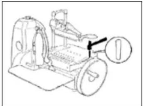
natural_image
Line drawing of a person using a stationary exercise machine with a numbered label (no text or symbols on the diagram itself)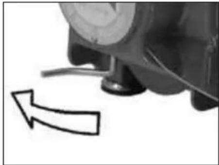
natural_image
Close-up of a mechanical component with a curved arrow indicating motion (no text or symbols)natural_image
Technical diagram of a mechanical device with a red downward arrow indicating a component (no text or symbols present)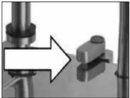
natural_image
Mechanical assembly diagram showing a bolted joint with an arrow indicating direction (no text or symbols)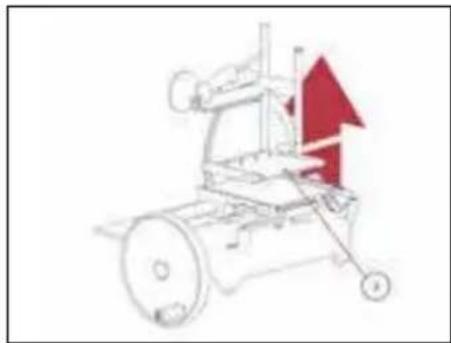
natural_image
Diagram of a mechanical device with a red upward arrow indicating growth or direction (no text or symbols present)(Fig. 6)
(Fig. 7)
(Fig. 8) (Fig. 9) (Fig. 10)
natural_image
Close-up of a hand holding a black mechanical device with a white arrow pointing to the button (no visible text or symbols)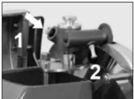
natural_image
Illustration of a robotic car with visible wheels and motion indicators (no text or symbols)(Fig. 11)
USER MANUAL: FLYWHEEL SLICER
MODELS:
B2, B3, Tribute, P15, L16, B114, B116

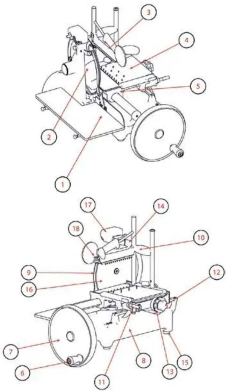
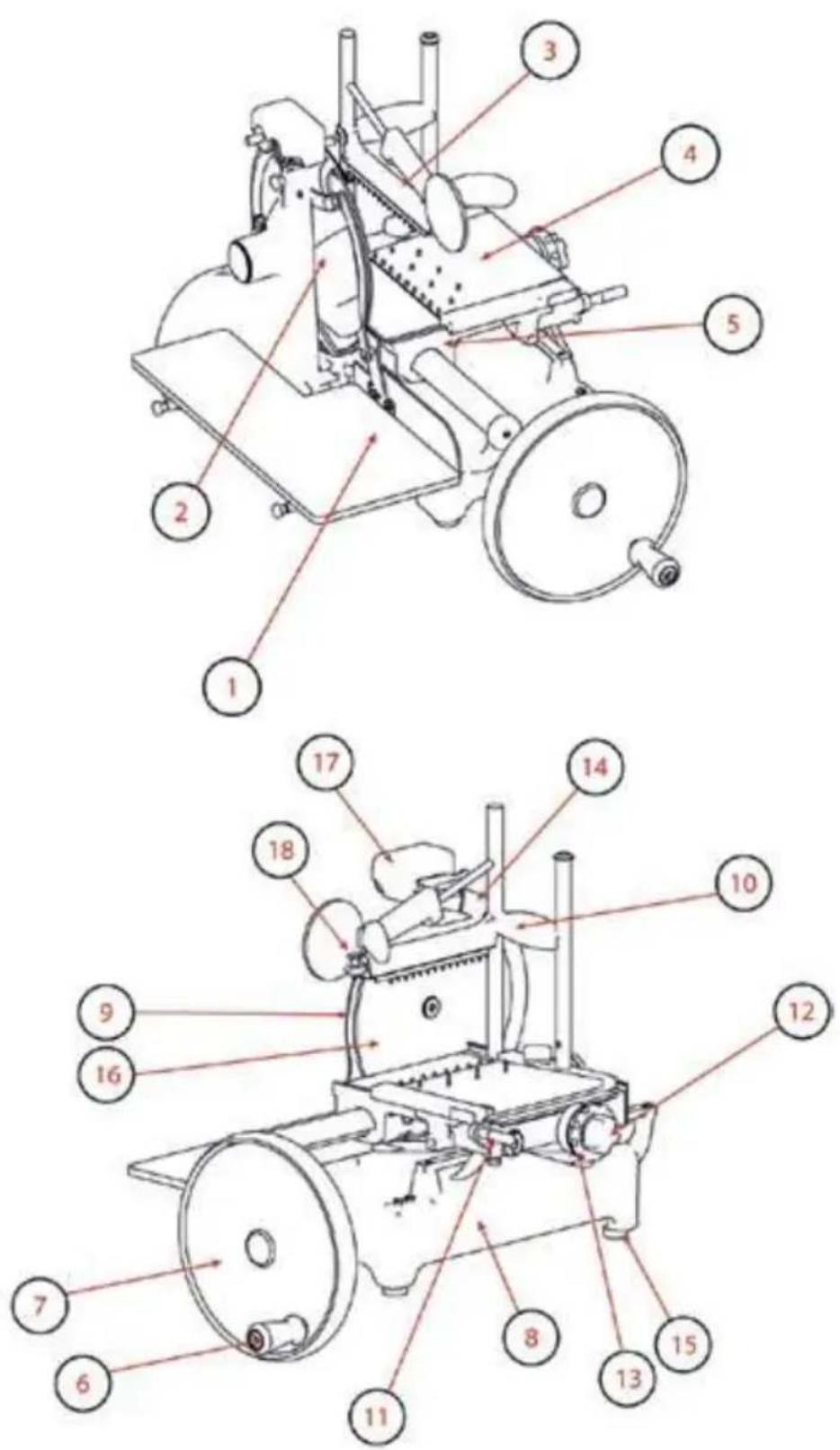
MAIN COMPONENTS
- Receiving plate
- Slice deflector
- Top clamp
- Meat table
- Carriage
- Flywheel operating handle
- Flywheel
- Casing
- Blade protection
- Vertical sliding top clamp
- Feed plate fast forward lever
- Feed plate forward handle
- Slice thickness regulating knob
- Blade cover
- Foot
- Blade
- Sharpener
Fig. 1
DESCRIPTION
Manual, flywheel slicer machine, equipped with a circular blade, suitable for cutting only the food products of the types and within the dimensional limits indicated in this manual. The main parts of the machine are shown in the general component diagram reported in picture 1.
SAFETY
The machines described in this manual comply with the latest European hygiene and safety standards. Pay attention to the following basic safety precautions:
- read all the instructions before using the machine;
- this product is not intended to be used by children;
- operate the machine only if properly trained and in perfect psycho-physical conditions;
- do not use the machine in any way other than what indicated in this manual;
- use the machines only in full structural, mechanical and system efficiency;
- install the machine in conformity to the instructions indicated in the "Installation" section;
- install the machine in a location out of the reach of personnel unauthorized to operate it and especially out of the reach of minors;
- stay highly concentrated when using the machine and avoid any distraction during use;
- do not allow the machine to be used by others who have not read and fully understood the content of this manual;
- do not wear baggy clothing or clothing with open sleeves;
- do not allow anyone else, other than the operator, to approach during product cutting operations;
- do not remove, cover or modify the tags located on the machine body and, in case of damage of these, replace them promptly;
- do not remove, modify or bypass any mechanical protective devices;
- slice only the permitted products, do not attempt cuts on prohibited type products;
- always keep clean and dry the sliced product resting surface, the work area all around the machine and the operator floor area;
- do not use the machine as a resting surface and do not place any objects on it other than food used for cutting operations;
- do not use the slicer when, due to normal wear, the distance between the edge of the blade and the blade guard ring exceeds 6 mm. In this case, contact the manufacturer or one of the Authorized Service Centers to change the blade.
- Immediately stop the machine in the event of a defect, abnormal operation, suspicion of breakdown, incorrect movement, unusual noises;
- use protective gloves for cleaning and maintenance operations;
- place and remove the goods to be sliced on the sliding plate only with the carriage completely pulled back and put the blade protection in safety position;
- for movement of the meat table during cutting operations use only the flywheel;
- never put your hands on the food product while slicing. AI-
ways keep your hands far from the blade;
- use of cutting accessories which were not provided by the manufacturer with the machine is prohibited.
The manufacturer declines any responsibility coming from inappropriate use, modifications and/or repairs carried out by the user or unauthorized personnel, use of replacement parts, which are not original or not specific for the machine model.
Operating conditions:
- Temperature from -5^ to +40^
- Max. humidity 95%
DO NOT SLICE:
- frozen food products;
- food products with bones;
- vegetables in general
- any other product not intended for food use.
Residual risks
The safety ring around the blade protects the operator from incidental contact with the blade although, in order to allow the sharpening operations, the protection in the sharpening area may not entirely eliminate the risk of cutting.
WARNING: during the blade cleaning and sharpening operations, pay extra attention to keep your hands as far as possible from the unprotected area. Use of protective gloves is recommended.
INSTALLATION OF THE MACHINE
If you do not use the stand (op-
tional), install the machine on a flat, smooth and dry surface suitable for supporting the weight of the machine itself plus the goods to be sliced. The recommended height of the worktop is approximately 80 cm. Lift the machine carefully and insert all the feet in the specific lodgings in the base. For some models, the front support feet can be unscrewed and placed in the desired position depending on the depth of the worktop.
To prevent damage, some models are packaged separately from the disassembled flywheel during transport. If the received machine flywheel is not assembled, follow these instructions:
- insert the flywheel on the shaft, checking correct correspondence with the flywheel-shaft sleeve holes (Fig. 3-A);
- insert the taper pin in the sleeve with the tapered end (smaller diameter) turned toward the sleeve itself (Fig. 3-B);
CAUTION! If the pin is correctly positioned, it will insert almost entirely without being forced.
- hammer down the pin to insert it fully.
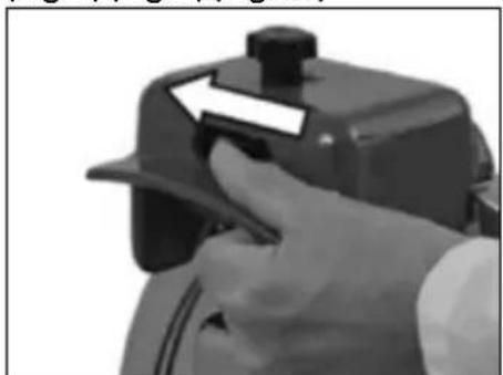
OPERATION
- Make sure that the blade is properly protected from the blade protection: use the blade protection locking lever, if present (Fig.4). Check that the thickness adjustment knob is in the safety position (position "0") (13);
- using the flywheel handle, rotate the flywheel (7) to bring the carriage (5) fully forward (toward the operator);
- pull back (away from the blade) the meat table (4) using the meat table rapid advance device (11) or meat table advance mechanism (12);
- place the product to be sliced on the sliding meat table;
- according to the model: a) grip both top clamp handles (10 - 18) and push them simultaneously toward the bottom until the product is locked; b) grip the top clamp sliding lever (10), lower it to the sliding end, grip the locking handle (18) and push it on the product until it is locked;
- arrange the desired slice thickness, rotating the knob at the same time and selecting a thickness;
- move the meat table with product forward (toward the blade), using the meat table rapid advance device (11) or meat table advanced mechanism (12);
CAUTION! Leave a space of 0.5 - 1 cm between the blade and the product.
- take off the protection from the blade using the locking lever, if present, or by moving the blade protection in its stand-by position to uncover the blade;
CAUTION Sharp blade, cutting hazard! When the blade is not covered by the guard, be extremely careful to keep your hands as far away from the unprotected area as possible.
- activate the flywheel by having it rotate it in the clockwise direction.
WARNING: risk of damages! Never turn the flywheel anti-clockwise, reverse flywheel rotation may seriously damage the machine.
- during the return movement of the carriage (towards the operator) the meat table will automatically move towards the blade;
- when the meat table gets to limit advancing towards the blade, stop slicing and lift up the top clamp. Use the meat table rapid advance device or the meat table advance mechanism to pull the meat table away from the blade. Reposition the product, relock it with the top clamp and restart slicing.;
- unload the product following the operations in the reverse order.
CAUTION Cutting hazard! After the cutting operation has been completed, turn the lever in the opposite direction: the protective ring will overlap the blade, eliminating the hazard.
CLEANING
Clean the machine at the end of their use and always before using, after a long period of inactivity. Use cut and tear resistant gloves and perform all operations with great care.
Products for cleaning: use only water and biodegradable mild detergent, using a soft, spongy cloth and a semi-rigid nylon brush for the sharp areas of the plate and the product holder. Do not clean the machine with jets of water or steam or similar methods.
DISMANTLING
- Check that the blade protection duly covers the blade (9);
- if the slice deflector is held by a screw, unscrew it and remove the slice deflector. If the slice
deflector is not held by a screw, open it by having it rotate from right to left;
- In B2 model remove the slice deflector; pull up the slice deflector support to remove it;
- remove the waste tray (Fig. 5-A); - remove the meat table: a) if there is a locking lever present (Fig. 5-B), rotate it in the counter-clockwise direction, lift the plate only and remove it; b) if there is a knob on the plate, unscrew it and lift the plate together with the top clamp (Fig. 5-C) and remove it; c) if no locking devices are present, lift the plate together with the top clamp and remove it (Fig. 5-C);
- slide off the receiving plate. If the plate is locked by two lateral pins, loosen them before sliding off the plate.

WARNING! For some models, push the meat table forward before lifting it with its top clamp arm.
CLEANING
- The blade: press a damp cloth on the surface of the blade and move it slowly from the center toward the outside on the blade cover side and the opposite side. In the same way, dry it using a dry cloth;

WARNING! Never activate the flywheel while ng the blade.
- the safety ring: use a soft brush to clean the area between the blade and the safety ring;

WARNING! Sharp blade, cutting hazard! When the blade is not covered by the guard, be extremely careful to keep your hands as far away from the unprotected area as possible.
- the machine body: use a
damp cloth or a sponge. Dry carefully.
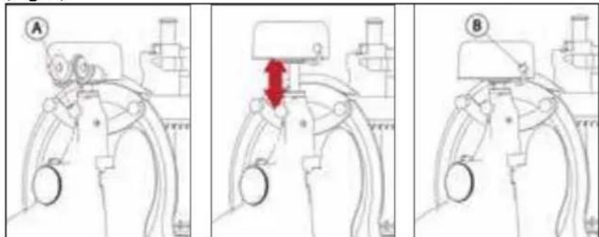
REASSEMBLING
- Check that the blade protection duly covers the blade (9);
- put the waste tray in its specific position;
- close the slice deflector;
- using the flywheel handle, rotate the flywheel (7) to bring the sliding meat table (4) fully forward (towards the operator);
- with a vertical movement from top to bottom, place the meat table in its position.

WARNING: risk of injury from sharp blade! For some models, after placing the meat table, push it forward in order to secure it completely in the carriage. If present, close the lever or tighten the knob on the meat table.
MAINTENANCE
Blade Sharpening
Frequency and duration of sharpening depend on the use of the equipment.

WARNING: risk of in-jury from sharp blade!
When the blade is not covered with the blade protection, pay extra attention to keep your hands as far as possible from the unprotected area.
For sharpening, follow the instruction according to the model:
FOR MODELS
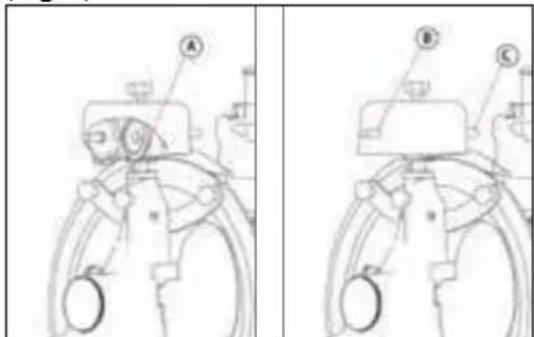
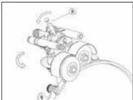
B2, B3, TRIBUTE (Fig. 6)
- Clean the blade, freeing it of greasy residue;
- check that the guard is covering the blade properly;
- loosen the meat table from
the blade;
- check the cover of the sharpener: if it is removable, just lift it up;
- if present, loosen the locking knob (A);
- lift the sharpener and rotate it 180^ ;
- lower the sharpener with care. The blade will be automatically centred between the two grinding wheels;
- if present, re-lock the knob.
- Press the button (B) for approximately 10-15 seconds and simultaneously rotate the flywheel. Release the button (B), press the button (C) for 2-3 seconds and then release it;
- stop turning the flywheel;
- only when the blade is fixed, return the sharpener to its original position and relock the knob;
- close the cover, if present.
FOR MODEL
P15 (Fig. 7)
- Check that the blade protection duly covers the blade;
- loosen the sharpener-locking knob (A);
- lift the sharpener and rotate it 180°;
- lower the sharpener back down with care; the blade will automatically center between the two grinding wheels;
- re-lock the knob;
- pull the lever (B) in an anticlockwise for approximately 10-15 seconds and simultaneously rotate the flywheel;
- stop turning the flywheel;
- only when the blade is fixed, return the sharpener to its original position and relock the knob.
FOR MODEL
B114 (Fig. 8)
- Clean the blade, freeing it of
greasy residue;
- check that the guard is covering the blade properly;
- loosen the meat table from the blade;
- lift the sharpener and rotate it 180°;
- lower the sharpener with care. The blade will be automatically centred between the two grinding wheels;
- push the sharpening lever (B) for approximately 10-15 seconds and simultaneously rotate the flywheel;
- release the sharpening lever, press the button (C) for 2-3 seconds and then release it;
- stop turning the flywheel;
- only when the blade is fixed, return the sharpener to its original position and relock the knob;
- close the cover, if present.
FOR MODEL
B116 (Fig. 9)
- Clean the blade, freeing it of greasy residue;
- check that the guard is covering the blade properly;
- loosen the meat table from the blade;
- lift the sharpener cover;
- lift the sharpener and rotate it 180^ in the direction of the blade;
- lower the sharpener with care. The blade will be automatically centred between the two grinding wheels;
- press the button (A) for approximately 10-15 seconds and simultaneously rotate the flywheel. Release the button (A), pull the lever (B) for 2-3 seconds and then release it;
- stop turning the flywheel;
- only when the blade is fixed, return the sharpener to its original position and relock the knob;
- close the cover.
FOR MODEL
L16, (Fig. 10)
- Check that the blade protection duly covers the blade;
- loosen the sharpener-locking knob;
- lift the sharpener and rotate it 180^ ;
- lower the sharpener back down with care; the blade will automatically center between the two grinding wheels;
- re-lock the knob;
- pull the lever anticlockwise for approximately 10-15 seconds and simultaneously rotate the flywheel;
- turn the lever clockwise for approximately 2-3 seconds and simultaneously rotate the flywheel;
- stop turning the flywheel;
- only when the blade is fixed, return the sharpener to its original position.

WARNING: risk of damages! Do not excessively
force (more than 2-3 seconds) the deburring operation to prevent damaging of the blade.
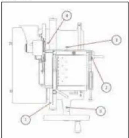
Lubrication (Fig. 11)
- Put some drops of oil over the bar (1) and in the junction of the slice thickness-regulating knob (2);
- put some drops of oil in the holes (3 and 4);
- put some drops of oil on the flywheel in its junction to the tree (5);
- briefly activate the flywheel. For lubrication only use acid free oil (we recommend Vaseline oil). Do not use vegetable oil.
SERVICE
No user-serviceable parts are inside. Refer servicing to qualified personnel. All the repair and replacement operations (like blade replacement, repair of structural parts, repair and/or re-placement of sub-base-plate components, or similar) shall be executed exclusively by personnel authorized by the manufacturer.
In the event service is need-ed, you may return your food slicer to the manufacturer or to one of the Authorized Service Centers. For information about service, centers please contact us at:
service@berkelinternational.com.

WARNING: risk of in-jury from sharp blade!
The blade replacement is mandatory if distance between the edge of the blade and the internal edge of the guard exceeds 6 mm.
WARRANTY AND RESPONSIBILITY
The manufacturer supplies The manufacturer supplies machines with a limited warranty of 24 months from the purchasing date. The warranty is extended only to defects that arise under intended use conditions and proper use. The warranty does not cover defects resulting from faults caused by transport, purchasers' incompetence or negligence, improper installation, unauthorised interventions, natural wear and tear greater than 10% of the nominal value. Moreover, the warranty does not cover components intrinsically subject to wear, such as blades and grinders, except in the event of evident manufacturing de
fects.
The manufacturer declines any direct and indirect responsibility coming from:
- failure to observe the instructions in this manual;
- use which does not conform to prevailing specific regulations in the country of installation;
- unauthorized modifications and/or repairs carried out on the machine;
- use of non-original accessories and replacement parts;
- exceptional events.
Transfer of ownership of the machine automatically defaults the manufacturer's liability for the machine in question.
The Identification tag on the base-plate indicates manufacturer, machine, technical information.
VOLANO
TRIBUTE
natural_image
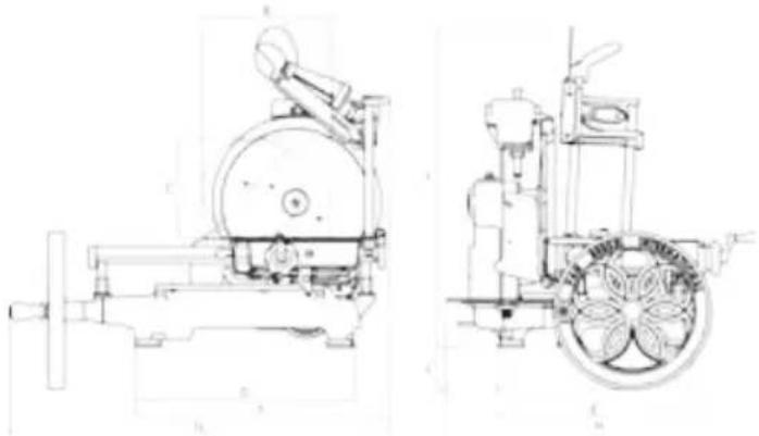
Technical line drawings of a mechanical device with front and side views (no text or symbols)VOLANO
P15
| MODEL TRIBUTE P15 | ||
| A 210 mm 180 mm | ||
| B 270 mm 210 mm | ||
| C 210 mm 180 mm | ||
| D 470 mm 430 mm | ||
| E 415 mm 250 mm | ||
| F 555 mm 505 mm | ||
| G 805 mm 720 mm | ||
| H 670 mm 600 mm | ||
| I 700 mm 570 mm | ||
| L 70 mm | ||
| SPECIFICATIONS | ||
| Circular cutting capacity 210 mm 180 mm | ||
| Rectangular cutting capacity 270x210 mm 210x180 mm | ||
| Max slice thickness 1,5 mm 1,5 mm | ||
| Blade diameter 300 mm 285 mm | ||
| Weight | 52 Kg | 60 kg |
VOLANO L16
VOLANO B2


| MODEL L16 B2 | ||
| A 210 mm 176 mm | ||
| B 260 mm 190 mm | ||
| C 200 mm 165 mm | ||
| D 305 mm 395 mm | ||
| E 640 mm 330 mm | ||
| F 880 mm 460 mm | ||
| G 600 mm 675 mm | ||
| H 545 mm 530 mm | ||
| I 750 mm 570 mm | ||
| L 33 mm | ||
| SPECIFICATIONS | ||
| Circular cutting capacity 210 mm 160 mm | ||
| Rectangular cutting capacity 260x200 mm 190x165 mm | ||
| Max slice thickness 4 mm 1,35 mm | ||
| Blade diameter 350 mm 265 mm | ||
| Weight | 105 Kg | 33 kg |
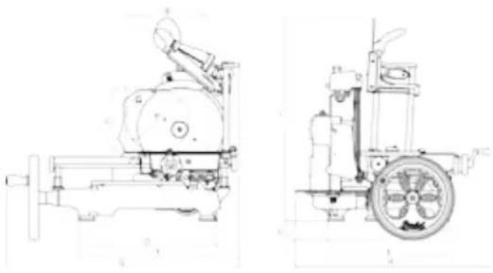
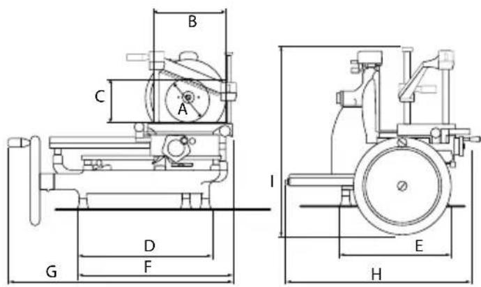
VOLANO
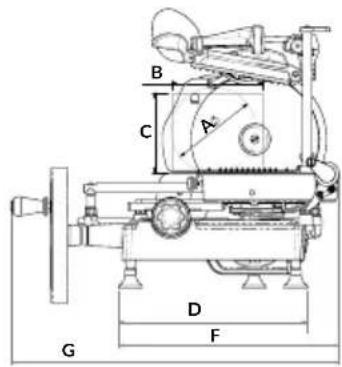
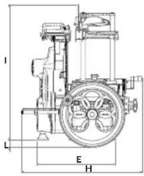
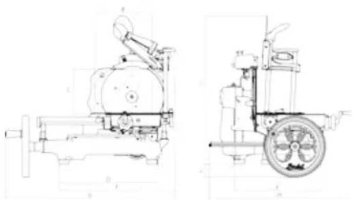
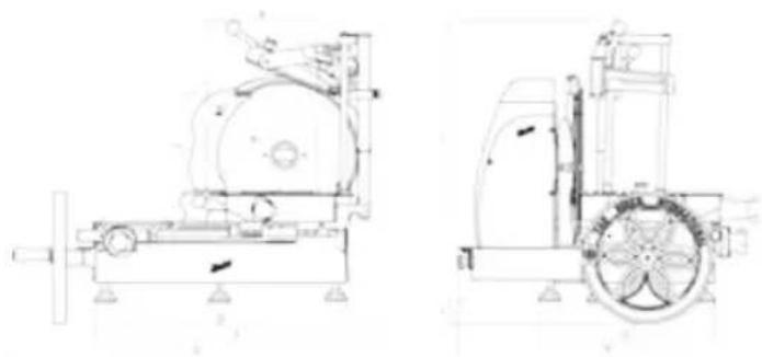
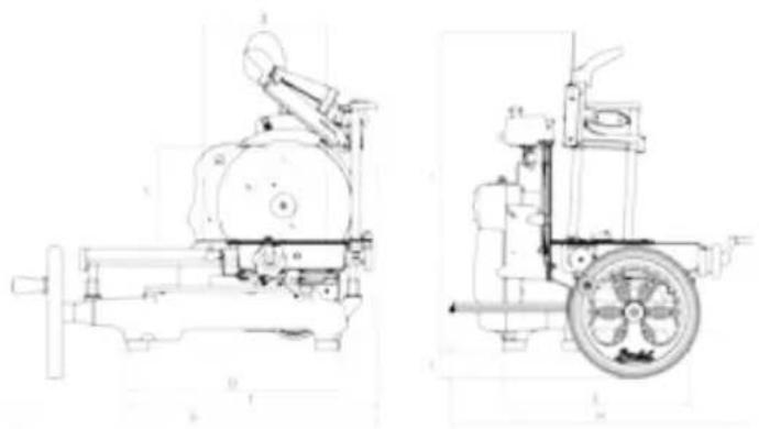
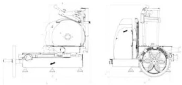
B3
VOLANO
B114
natural_image
Technical line drawing of a mechanical device with front and side views (no text or symbols)
natural_image
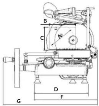
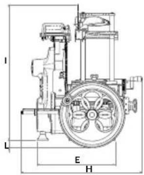
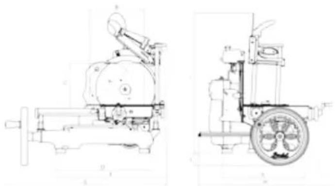
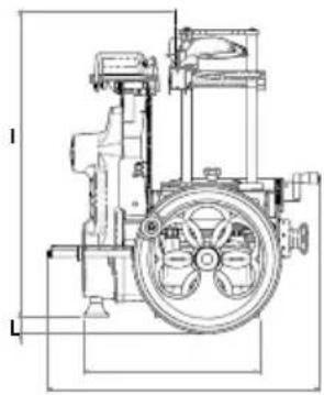
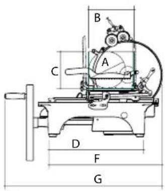
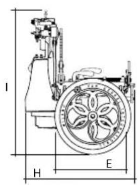
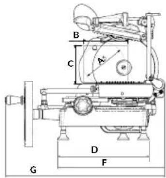
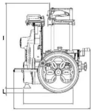
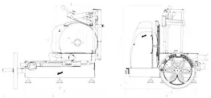
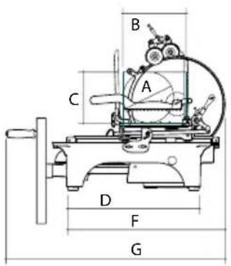
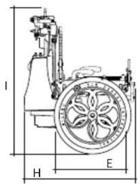
Technical line drawings of two mechanical devices, one with a circular component and the other with a wheel and fan (no text or symbols)| MODEL B3 B114 | ||
| A 210 mm 215 mm | ||
| B 270 mm 280 mm | ||
| C 210 mm 215 mm | ||
| D 460 mm 470 mm | ||
| E 405 mm 415 mm | ||
| F 550 mm 555 mm | ||
| G 805 mm 825 mm | ||
| H 670 mm 670 mm | ||
| I 700 mm 700 mm | ||
| L 65 mm 95 mm | ||
| SPECIFICATIONS | ||
| Circular cutting capacity 210 mm 215 mm | ||
| Rectangular cutting capacity 270x210 mm 280x215 mm | ||
| Max slice thickness 1,5 mm 1,5 mm | ||
| Blade diameter | 300 mm 319 mm | |
| Weight | 46 Kg | 55 kg |
VOLANO
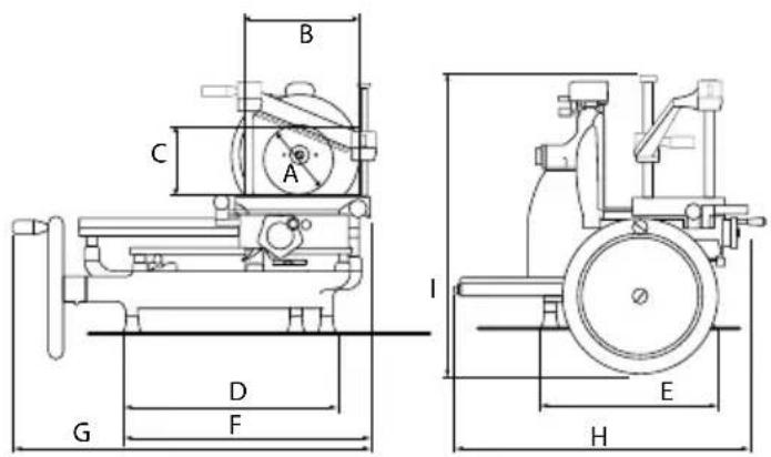
B116

natural_image
Technical line drawings of two mechanical components, one with a cylindrical housing and the other a wheel-barrowed cart (no text or symbols)| MODEL B116 | ||
| A 260 mm | ||
| B 290 mm | ||
| C 260 mm | ||
| D 590 mm | ||
| E 550 mm | ||
| F 755 mm | ||
| G 960 mm | ||
| H 780 mm | ||
| I 720 mm | ||
| L 60 mm | ||
| SPECIFICATIONS | ||
| Circular cutting capacity 260 mm | ||
| Rectangular cutting capacity 290x260 mm | ||
| Max slice thickness 4 mm | ||
| Blade diameter 370 mm | ||
| Weight 80 Kg | ||
Note: As we actually strive to improve our products, specifications are necessarily subject to change without notice.
MANUALE D'USO: AFFETTATRICE MANUALE A VOLANO - VERSIONE EU
MODELLI:
B2, B3, Tribute, P15, L16, B114, B116

COMPONENTI PRINCIPALI
natural_image
Technical line drawings of two mechanical components, one with a pump and motor assembly, the other with a wheel and fan (no text or symbols)VOLANO P15
natural_image
Technical line drawings of a mechanical device with front and side views (no text or symbols)VOLANO
B114
natural_image
Technical line drawings of a mechanical device with two views (top and side), no visible text or symbols.natural_image
Technical line drawings of two mechanical components, one with a pump and the other a wheel-barrowed machine (no text or symbols)B2, B3, Tribute, P15, L16, B114, B116
HAUPTBESTANDTEILE
natural_image
Technical line drawings of two mechanical components, one with a pump and the other with a wheel and gear (no text or symbols)VOLANO P15

natural_image
Technical line drawing of a mechanical device with front and side views (no text or symbols)VOLANO
B114

natural_image
Technical line drawings of two mechanical devices, one with a circular component and the other with a wheel-like structure (no text or symbols)| MODELL B3 B114 | ||
| A 210 mm 215 mm | ||
| B 270 mm 280 mm | ||
| C 210 mm 215 mm | ||
| D 460 mm 470 mm | ||
| E 405 mm 415 mm | ||
| F 550 mm 555 mm | ||
| G 805 mm 825 mm | ||
| H 670 mm 670 mm | ||
| I 700 mm 700 mm | ||
| L 65 mm 95 mm | ||
| TECHNISCHE MERKMALE | ||
| Schnittleistung (rund) 210 mm 215 mm | ||
| Schnittleistung (rechteckig) 270x210 mm 280x215 mm | ||
| Max. Schnittstärke 1,5 mm 1,5 mm | ||
| Kilngedurchmesser | 300 mm 319 mm | |
| Gewicht | 46 Kg | 55 kg |
VOLANO
B116

natural_image
Technical line drawings of a mechanical device with front and side views (no text or symbols)B2, B3, Tribute, P15, L16, B114, B116
ÉLÉMENTS PRINCIPAUX
Lubrification (Fig. 11)
natural_image
Technical line drawings of two mechanical components, one with a pump and the other with a wheel and gear (no text or symbols)VOLANO P15

natural_image
Technical line drawings of a mechanical device with front and side views (no text or symbols)
natural_image
Technical line drawings of two mechanical devices with no visible text or symbolsnatural_image
Technical line drawings of a mechanical device with front and side views (no text or symbols)B2, B3, Tribute, P15, L16, B114, B116

ČÁSTI STROJE
natural_image
Technical line drawings of two mechanical components, one with a pump and valve mechanism, the other with a wheel and fan assembly (no text or labels)VOLANO P15

natural_image
Technical line drawings of a mechanical device with front and side views (no text or symbols)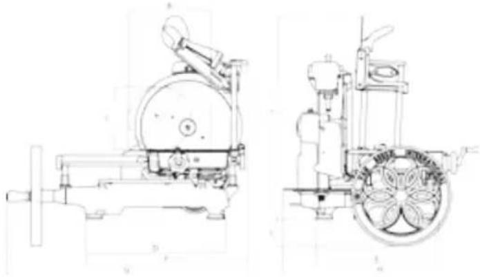
natural_image
Technical line drawings of two mechanical devices, one with a circular component and the other with a wheel and fan (no text or symbols)natural_image
Technical line drawings of two mechanical components with no visible text or symbolsB2, B3, Tribute, P15, L16, B114, B116

Fig. 1
MASKINDELE
natural_image
Technical line drawings of two mechanical components, one with a pump and the other with a wheel and gear (no text or symbols)VOLANO P15

| MODELLER TRIBUTE P15 | ||
| A 210 mm 180 mm | ||
| B 270 mm 210 mm | ||
| C 210 mm 180 mm | ||
| D 470 mm 430 mm | ||
| E 415 mm 250 mm | ||
| F 555 mm 505 mm | ||
| G 805 mm 720 mm | ||
| H 670 mm 600 mm | ||
| I 700 mm 570 mm | ||
| L 70 mm | ||
| SPECIFIKATIONER | ||
| Kapacitet rundskæring 210 mm 180 mm | ||
| Kapacitet lineær skæring 270x210 mm 210x180 mm | ||
| Maks. skivetykkelse 1,5 mm 1,5 mm | ||
| Klingediameter 300 mm 285 mm | ||
| Vægt | 52 Kg | 60 kg |
VOLANO
L16
VOLANO B2


| MODELLER L16 B2 | ||
| A 210 mm 176 mm | ||
| B 260 mm 190 mm | ||
| C 200 mm 165 mm | ||
| D 305 mm 395 mm | ||
| E 640 mm 330 mm | ||
| F 880 mm 460 mm | ||
| G 600 mm 675 mm | ||
| H 545 mm 530 mm | ||
| I 750 mm 570 mm | ||
| L 33 mm | ||
| SPECIFICATIONER | ||
| Kapacitet rundskæring 210 mm 160 mm | ||
| Kapacitet lineær skæring 260x200 mm 190x165 mm | ||
| Maks. skivetykkelse 4 mm 1,35 mm | ||
| Klingediameter 350 mm 265 mm | ||
| Vægt | 105 Kg | 33 kg |
VOLANO
B3
VOLANO
B114

natural_image
Technical line drawings of a mechanical device with front and side views (no text or symbols)
natural_image
Technical line drawings of two mechanical devices with no visible text or symbols| MODELLER B3 B114 | ||
| A 210 mm 215 mm | ||
| B 270 mm 280 mm | ||
| C 210 mm 215 mm | ||
| D 460 mm 470 mm | ||
| E 405 mm 415 mm | ||
| F 550 mm 555 mm | ||
| G 805 mm 825 mm | ||
| H 670 mm 670 mm | ||
| I 700 mm 700 mm | ||
| L 65 mm 95 mm | ||
| SPECIFIKATIONER | ||
| Kapacitet rundskæring 210 mm 215 mm | ||
| Kapacitet lineær skæring 270x210 mm 280x215 mm | ||
| Maks. skivetykkelse 1,5 mm 1,5 mm | ||
| Klingediameter | 300 mm 319 mm | |
| Vægt | 46 Kg | 55 kg |
VOLANO
B116

natural_image
Technical line drawings of a mechanical device with front and side views (no text or symbols)| MODELLER B116 | ||
| A 260 mm | ||
| B 290 mm | ||
| C 260 mm | ||
| D 590 mm | ||
| E 550 mm | ||
| F 755 mm | ||
| G 960 mm | ||
| H 780 mm | ||
| I 720 mm | ||
| L 60 mm | ||
| SPECIFICATIONER | ||
| Kapacitet rundskæring 260 mm | ||
| Kapacitet lineær skæring 290x260 mm | ||
| Maks. skivetykkelse 4 mm | ||
| Klingediameter 370 mm | ||
| Vægt 80 Kg | ||
B2, B3, Tribute, P15, L16, B114, B116

COMPONENTES PRINCIPALES
natural_image
Technical line drawings of two mechanical components, one with a pump and the other with a wheel and gear (no text or symbols)VOLANO P15

| MODELO TRIBUTE P15 | ||
| A 210 mm 180 mm | ||
| B 270 mm 210 mm | ||
| C 210 mm 180 mm | ||
| D 470 mm 430 mm | ||
| E 415 mm 250 mm | ||
| F 555 mm 505 mm | ||
| G 805 mm 720 mm | ||
| H 670 mm 600 mm | ||
| I 700 mm 570 mm | ||
| L 70 mm | ||
| ESPECIFICACIONES | ||
| Capacidad (circular) 210 mm 180 mm | ||
| Capacidad (rectangular) 270x210 mm 210x180 mm | ||
| Capacidad máxima de corte 1,5 mm 1,5 mm | ||
| Diámetro cuchilla 300 mm 285 mm | ||
| Peso | 52 Kg | 60 kg |
VOLANO
L16
VOLANO B2


| MODELO L16 B2 | ||
| A 210 mm 176 mm | ||
| B 260 mm 190 mm | ||
| C 200 mm 165 mm | ||
| D 305 mm 395 mm | ||
| E 640 mm 330 mm | ||
| F 880 mm 460 mm | ||
| G 600 mm 675 mm | ||
| H 545 mm 530 mm | ||
| I 750 mm 570 mm | ||
| L 33 mm | ||
| ESPECIFICACIONES | ||
| Capacidad (circular) 210 mm 160 mm | ||
| Capacidad (rectangular) 260x200 mm 190x165 mm | ||
| Capacidad máxima de corte 4 mm 1,35 mm | ||
| Diámetro cuchilla 350 mm 265 mm | ||
| Peso | 105 Kg | 33 kg |
VOLANO B3
natural_image
Technical line drawing of a mechanical device with front and side views (no text or symbols)VOLANO
B114

natural_image
Technical line drawings of two mechanical devices, one with a circular component and the other with a wheel-like structure (no text or symbols)| MODELO B3 B114 | ||
| A 210 mm 215 mm | ||
| B 270 mm 280 mm | ||
| C 210 mm 215 mm | ||
| D 460 mm 470 mm | ||
| E 405 mm 415 mm | ||
| F 550 mm 555 mm | ||
| G 805 mm 825 mm | ||
| H 670 mm 670 mm | ||
| I 700 mm 700 mm | ||
| L 65 mm 95 mm | ||
| ESPECIFICACIONES | ||
| Capacidad (circular) 210 mm 215 mm | ||
| Capacidad (rectangular) 270x210 mm 280x215 mm | ||
| Capacidad máxima de corte 1,5 mm 1,5 mm | ||
| Diámetro cuchilla | 300 mm 319 mm | |
| Peso | 46 Kg | 55 kg |
VOLANO
B116

natural_image
Technical line drawings of a mechanical device with front and side views (no text or symbols)B2, B3, Tribute, P15, L16, B114, B116

TÄRKEIMMÄT OSAT
natural_image
Technical line drawings of two mechanical components, one with a pump and motor assembly, the other with a wheel and gear mechanism (no text or labels)VOLANO P15

natural_image
Technical line drawing of a mechanical pump assembly (no text or labels)natural_image
Technical line drawing of a mechanical device with front and side views (no text or symbols)
natural_image
Technical line drawings of two mechanical devices, one with a circular component and the other with a wheel and fan (no text or symbols)natural_image
Technical line drawings of two mechanical components, one with a cylindrical housing and the other a wheel-barrowed cart (no text or symbols)B2, B3, Tribute, P15, L16, B114, B116

Fig. 1
ČÁSTI STROJE
natural_image
Technical line drawings of two mechanical components, one with a pump and the other with a wheel and gear (no text or labels)VOLANO P15

| MODELIUI TRIBUTE P15 | ||
| A 210 mm 180 mm | ||
| B 270 mm 210 mm | ||
| C 210 mm 180 mm | ||
| D 470 mm 430 mm | ||
| E 415 mm 250 mm | ||
| F 555 mm 505 mm | ||
| G 805 mm 720 mm | ||
| H 670 mm 600 mm | ||
| I 700 mm 570 mm | ||
| L 70 mm | ||
| SPECIFIKACIJOS | ||
| Pjovimo apvalia forma pajègumas | 210 mm 180 mm | |
| Pjovimo stačiakampe forma pajègumas | 270x210 mm 210x180 mm | |
| Maksimalus griežinėlio storis | 1,5 mm 1,5 mm | |
| Peilio skersmuo | 300 mm 285 mm | |
| Svoris | 52 Kg 60 kg | |
VOLANO L16
VOLANO B2


natural_image
Technical line drawing of a mechanical pump or motor assembly (no text or symbols)| MODELIUI L16 B2 | ||
| A 210 mm 176 mm | ||
| B 260 mm 190 mm | ||
| C 200 mm 165 mm | ||
| D 305 mm 395 mm | ||
| E 640 mm 330 mm | ||
| F 880 mm 460 mm | ||
| G 600 mm 675 mm | ||
| H 545 mm 530 mm | ||
| I 750 mm 570 mm | ||
| L 33 mm | ||
| SPECIFIKACIJOS | ||
| Pjovimo apvalia forma pajėgumas | 210 mm 160 mm | |
| Pjovimo stačiakampe forma pajėgumas | 260x200 mm 190x165 mm | |
| Maksimalus griežinėlio storis | 4 mm 1,35 mm | |
| Peilio skersmuo | 350 mm 265 mm | |
| Svoris | 105 Kg 33 kg | |
VOLANO
B3

natural_image
Technical line drawings of a mechanical device with front and side views (no text or symbols)VOLANO
B114

natural_image
Technical line drawings of two mechanical devices, one with a circular component and the other with a wheel-like structure (no text or symbols)| MODELIUI B3 B114 | ||
| A 210 mm 215 mm | ||
| B 270 mm 280 mm | ||
| C 210 mm 215 mm | ||
| D 460 mm 470 mm | ||
| E 405 mm 415 mm | ||
| F 550 mm 555 mm | ||
| G 805 mm 825 mm | ||
| H 670 mm 670 mm | ||
| I 700 mm 700 mm | ||
| L 65 mm 95 mm | ||
| SPECIFIKACIJOS | ||
| Pjovimo apvalia forma pajègumas | 210 mm 215 mm | |
| Pjovimo stačiakampe forma pajègumas | 270x210 mm 280x215 mm | |
| Maksimalus griežinėlio storis | 1,5 mm 1,5 mm | |
| Peilio skersmuo | 300 mm 319 mm | |
| Svoris | 46 Kg 55 kg | |
VOLANO
B116

natural_image
Technical line drawings of two mechanical components, one with a cylindrical housing and the other a wheel-mounted device (no text or symbols)| MODELIUI B116 | ||
| A 260 mm | ||
| B 290 mm | ||
| C 260 mm | ||
| D 590 mm | ||
| E 550 mm | ||
| F 755 mm | ||
| G 960 mm | ||
| H 780 mm | ||
| I 720 mm | ||
| L 60 mm | ||
| SPECIFIKACIJOS | ||
| Pjovimo apvalia forma pajėgumas | 260 mm | |
| Pjovimo stačiakampe forma pajėgumas | 290x260 mm | |
| Maksimalus griežinėlio storis | 4 mm | |
| Peilio skersmuo | 370 mm | |
| Svoris | 80 Kg | |
HANDLEIDING: HANDSNIJMACHINE
MODELLEN:
B2, B3, Tribute, P15, L16, B114, B116

ONDERDELEN VAN DE MACHINE
natural_image
Technical line drawings of two mechanical components, one with a pump and the other with a wheel and gear (no text or symbols)VOLANO P15

| MODELLEN TRIBUTE P15 | ||
| A 210 mm 180 mm | ||
| B 270 mm 210 mm | ||
| C 210 mm 180 mm | ||
| D 470 mm 430 mm | ||
| E 415 mm 250 mm | ||
| F 555 mm 505 mm | ||
| G 805 mm 720 mm | ||
| H 670 mm 600 mm | ||
| I 700 mm 570 mm | ||
| L 70 mm | ||
| SPECIFICATIES | ||
| Snijcapaciteit (rond) 210 mm 180 mm | ||
| Snijcapaciteit (rechthoekig) 270x210 mm 210x180 mm | ||
| Maximale snijdikte 1,5 mm 1,5 mm | ||
| Mesdiameter 300 mm 285 mm | ||
| Gewicht | 52 Kg | 60 kg |
VOLANO
L16
VOLANO
B2


natural_image
Technical line drawing of a mechanical pump or motor assembly (no text or symbols)| MODELLEN L16 B2 | ||
| A 210 mm 176 mm | ||
| B 260 mm 190 mm | ||
| C 200 mm 165 mm | ||
| D 305 mm 395 mm | ||
| E 640 mm 330 mm | ||
| F 880 mm 460 mm | ||
| G 600 mm 675 mm | ||
| H 545 mm 530 mm | ||
| I 750 mm 570 mm | ||
| L 33 mm | ||
| SPECIFICATIES | ||
| Snijcapaciteit (rond) 210 mm 160 mm | ||
| Snijcapaciteit (rechthoekig) 260x200 mm 190x165 mm | ||
| Maximale snijdikte 4 mm 1,35 mm | ||
| Mesdiameter 350 mm 265 mm | ||
| Gewicht | 105 Kg | 33 kg |
VOLANO
B3
VOLANO
B114

natural_image
Technical line drawing of a mechanical device with front and side views (no text or symbols)
natural_image
Technical line drawings of two mechanical devices, one with a circular component and the other with a wheel and fan (no text or symbols)| MODELLEN B3 B114 | ||
| A 210 mm 215 mm | ||
| B 270 mm 280 mm | ||
| C 210 mm 215 mm | ||
| D 460 mm 470 mm | ||
| E 405 mm 415 mm | ||
| F 550 mm 555 mm | ||
| G 805 mm 825 mm | ||
| H 670 mm 670 mm | ||
| I 700 mm 700 mm | ||
| L 65 mm 95 mm | ||
| SPECIFICATIES | ||
| Snijcapaciteit (rond) 210 mm 215 mm | ||
| Snijcapaciteit (rechthoekig) 270x210 mm 280x215 mm | ||
| Maximale snijdikte 1,5 mm 1,5 mm | ||
| Mesdiameter | 300 mm 319 mm | |
| Gewicht | 46 Kg | 55 kg |
VOLANO
B116
natural_image
Technical line drawings of a mechanical device with front and side views (no text or symbols)| MODELLEN B116 | ||
| A 260 mm | ||
| B 290 mm | ||
| C 260 mm | ||
| D 590 mm | ||
| E 550 mm | ||
| F 755 mm | ||
| G 960 mm | ||
| H 780 mm | ||
| I 720 mm | ||
| L 60 mm | ||
| SPECIFICATIES | ||
| Snijcapaciteit (rond) 260 mm | ||
| Snijcapaciteit (rechthoekig) 290x260 mm | ||
| Maximale snijdikte 4 mm | ||
| Mesdiameter 370 mm | ||
| Gewicht 80 Kg | ||
B2, B3, Tribute, P15, L16, B114, B116

Fig. 1
MASKINDELER
natural_image
Technical line drawings of two mechanical components, one with a pump and motor assembly, the other with a wheel and gear mechanism (no text or labels)VOLANO P15

| MODELL TRIBUTE P15 | ||
| A 210 mm 180 mm | ||
| B 270 mm 210 mm | ||
| C 210 mm 180 mm | ||
| D 470 mm 430 mm | ||
| E 415 mm 250 mm | ||
| F 555 mm 505 mm | ||
| G 805 mm 720 mm | ||
| H 670 mm 600 mm | ||
| I 700 mm 570 mm | ||
| L 70 mm | ||
| SPESIFIKASJONER | ||
| Sirkelformet skjærekapasitet 210 mm 180 mm | ||
| Rektangulær skjærekapasitet 270x210 mm 210x180 mm | ||
| Maksimal skivetykkelse 1,5 mm 1.5 mm | ||
| Diameter skjæreblad 300 mm 285 mm | ||
| Vekt | 52 Kg | 60 kg |
VOLANO L16
VOLANO B2


natural_image
Technical line drawing of a mechanical pump or motor assembly (no text or symbols)| MODELL L16 B2 | ||
| A 210 mm 176 mm | ||
| B 260 mm 190 mm | ||
| C 200 mm 165 mm | ||
| D 305 mm 395 mm | ||
| E 640 mm 330 mm | ||
| F 880 mm 460 mm | ||
| G 600 mm 675 mm | ||
| H 545 mm 530 mm | ||
| I 750 mm 570 mm | ||
| L 33 mm | ||
| SPESIFIKASJONER | ||
| Sirkelformet skjærekapasitet 210 mm 160 mm | ||
| Rektangulær skjærekapasitet 260x200 mm 190x165 mm | ||
| Maksimal skivetykkelse 4 mm 1,35 mm | ||
| Diameter skjæreblad 350 mm 265 mm | ||
| Vekt | 105 Kg | 33 kg |
VOLANO
B3
VOLANO
B114
natural_image
Technical line drawings of a mechanical device with front and side views (no text or symbols)
natural_image
Technical line drawings of two mechanical devices with no visible text or symbols| MODELL B3 B114 | ||
| A 210 mm 215 mm | ||
| B 270 mm 280 mm | ||
| C 210 mm 215 mm | ||
| D 460 mm 470 mm | ||
| E 405 mm 415 mm | ||
| F 550 mm 555 mm | ||
| G 805 mm 825 mm | ||
| H 670 mm 670 mm | ||
| I 700 mm 700 mm | ||
| L 65 mm 95 mm | ||
| SPESIFIKASJONER | ||
| Sirkelformet skjærekapasitet 210 mm 215 mm | ||
| Rektangulær skjærekapasitet 270x210 mm 280x215 mm | ||
| Maksimal skivetykkelse 1,5 mm 1,5 mm | ||
| Diameter skjæreblad | 300 mm 319 mm | |
| Vekt | 46 Kg | 55 kg |
VOLANO
B116

natural_image
Technical line drawings of two mechanical components, one with a cylindrical housing and the other a wheel-mounted device (no text or symbols)| MODELL B116 | ||
| A 260 mm | ||
| B 290 mm | ||
| C 260 mm | ||
| D 590 mm | ||
| E 550 mm | ||
| F 755 mm | ||
| G 960 mm | ||
| H 780 mm | ||
| I 720 mm | ||
| L 60 mm | ||
| SPESIFIKASJONER | ||
| Sirkelformet skjærekapasitet 260 mm | ||
| Rektangulær skjærekapasitet 290x260 mm | ||
| Maksimal skivetykkelse 4 mm | ||
| Diameter skjæreblad 370 mm | ||
| Vekt 80 Kg | ||
B2, B3, Tribute, P15, L16, B114, B116

PARTES DA MÁQUINA
natural_image
Technical line drawings of two mechanical components, one with a pump and motor assembly, the other with a wheel and fan (no text or symbols)VOLANO P15

| MODELO TRIBUTE P15 | ||
| A 210 mm 180 mm | ||
| B 270 mm 210 mm | ||
| C 210 mm 180 mm | ||
| D 470 mm 430 mm | ||
| E 415 mm 250 mm | ||
| F 555 mm 505 mm | ||
| G 805 mm 720 mm | ||
| H 670 mm 600 mm | ||
| I 700 mm 570 mm | ||
| L 70 mm | ||
| ESPECIFICAÇÕES | ||
| Capacidade de corte circular 210 mm 180 mm | ||
| Capacidade de corte rectangular 270x210 mm 210x180 mm | ||
| Espessura máxima da fatia 1,5 mm 1,5 mm | ||
| Diâmetro da lâmina 300 mm 285 mm | ||
| Peso 52 Kg 60 kg | ||
VOLANO
L16
VOLANO
B2


natural_image
Technical line drawing of a mechanical pump or motor assembly (no text or symbols)| MODELO L16 B2 | ||
| A 210 mm 176 mm | ||
| B 260 mm 190 mm | ||
| C 200 mm 165 mm | ||
| D 305 mm 395 mm | ||
| E 640 mm 330 mm | ||
| F 880 mm 460 mm | ||
| G 600 mm 675 mm | ||
| H 545 mm 530 mm | ||
| I 750 mm 570 mm | ||
| L 33 mm | ||
| ESPECIFICAÇÕES | ||
| Capacidade de corte circular 210 mm 160 mm | ||
| Capacidade de corte rectangular 260x200 mm 190x165 mm | ||
| Espessura máxima da fatia 4 mm 1,35 mm | ||
| Diâmetro da lâmina 350 mm 265 mm | ||
| Peso 105 Kg 33 kg | ||
VOLANO B3

natural_image
Technical line drawings of a mechanical device with front and side views (no text or symbols)VOLANO
B114

natural_image
Technical line drawings of two mechanical devices, one with a circular component and the other with a wheel and fan (no text or symbols)| MODELO B3 B114 | ||
| A 210 mm 215 mm | ||
| B 270 mm 280 mm | ||
| C 210 mm 215 mm | ||
| D 460 mm 470 mm | ||
| E 405 mm 415 mm | ||
| F 550 mm 555 mm | ||
| G 805 mm 825 mm | ||
| H 670 mm 670 mm | ||
| I 700 mm 700 mm | ||
| L 65 mm 95 mm | ||
| ESPECIFICAÇÕES | ||
| Capacidade de corte circular 210 mm 215 mm | ||
| Capacidade de corte rectangular 270x210 mm 280x215 mm | ||
| Espessura máxima da fatia 1,5 mm 1,5 mm | ||
| Diâmetro da lâmina 300 mm 319 mm | ||
| Peso | 46 Kg | 55 kg |
VOLANO
B116
natural_image
Technical line drawings of two mechanical components, one with a pump and the other with a wheel and gear (no text or symbols)B2, B3, Tribute, P15, L16, B114, B116

Fig. 1
PĂRȚI ALE MAȘINII
natural_image
Technical line drawings of two mechanical components, one with a pump and valve mechanism, the other with a wheel and fan assembly (no text or labels)VOLANO P15

| MODEL TRIBUTE P15 | ||
| A 210 mm 180 mm | ||
| B 270 mm 210 mm | ||
| C 210 mm 180 mm | ||
| D 470 mm 430 mm | ||
| E 415 mm 250 mm | ||
| F 555 mm 505 mm | ||
| G 805 mm 720 mm | ||
| H 670 mm 600 mm | ||
| I 700 mm 570 mm | ||
| L 70 mm | ||
| SPECIFICATII | ||
| Capacitate de tăiere circulară | 210 mm 180 mm | |
| Capacitate de tăiere rectangulară | 270x210 mm 210x180 mm | |
| Grosime maximă felie | 1,5 mm 1,5 mm | |
| Diametru lamă | 300 mm 285 mm | |
| Greutate | 52 Kg 60 kg | |
VOLANO L16
VOLANO B2
natural_image
Technical line drawing of a mechanical pump assembly (no text or labels)| MODEL L16 B2 | ||
| A 210 mm 176 mm | ||
| B 260 mm 190 mm | ||
| C 200 mm 165 mm | ||
| D 305 mm 395 mm | ||
| E 640 mm 330 mm | ||
| F 880 mm 460 mm | ||
| G 600 mm 675 mm | ||
| H 545 mm 530 mm | ||
| I 750 mm 570 mm | ||
| L 33 mm | ||
| SPECIFICATII | ||
| Capacitate de tăiere circulară | 210 mm 160 mm | |
| Capacitate de tăiere rectangulară | 260x200 mm 190x165 mm | |
| Grosime maximă felie | 4 mm 1,35 mm | |
| Diametru lamă | 350 mm 265 mm | |
| Greutate | 105 Kg 33 kg | |
VOLANO
B3
VOLANO
B114

natural_image
Technical line drawings of a mechanical device with front and side views (no text or symbols)
natural_image
Technical line drawings of two mechanical devices with no visible text or symbols| MODEL B3 B114 | ||
| A 210 mm 215 mm | ||
| B 270 mm 280 mm | ||
| C 210 mm 215 mm | ||
| D 460 mm 470 mm | ||
| E 405 mm 415 mm | ||
| F 550 mm 555 mm | ||
| G 805 mm 825 mm | ||
| H 670 mm 670 mm | ||
| I 700 mm 700 mm | ||
| L 65 mm 95 mm | ||
| SPECIFICAȚII | ||
| Capacitate de tăiere circulară | 210 mm 215 mm | |
| Capacitate de tăiere rectangulară | 270x210 mm 280x215 mm | |
| Grosime maximă felie | 1,5 mm 1,5 mm | |
| Diametru lamă | 300 mm 319 mm | |
| Greutate | 46 Kg 55 kg | |
VOLANO
B116
natural_image
Technical line drawings of two mechanical components, one with a cylindrical housing and the other a wheel assembly (no text or symbols)B2, B3, Tribute, P15, L16, B114, B116

ČASTI STROJA
natural_image
Technical line drawings of two mechanical components, one with a pump and motor assembly, the other with a wheel and fan (no text or symbols)VOLANO P15

| MODEL TRIBUTE P15 | ||
| A 210 mm 180 mm | ||
| B 270 mm 210 mm | ||
| C 210 mm 180 mm | ||
| D 470 mm 430 mm | ||
| E 415 mm 250 mm | ||
| F 555 mm 505 mm | ||
| G 805 mm 720 mm | ||
| H 670 mm 600 mm | ||
| I 700 mm 570 mm | ||
| L 70 mm | ||
| ŠPECIFIKÁCIE | ||
| Výkon pri kruhovom rezaní | 210 mm 180 mm | |
| Výkon pri obdížnikovom rezaní | 270x210 mm 210x180 mm | |
| Maximálna hrúbka plátku | 1,5 mm 1,5 mm | |
| Priemer noža | 300 mm 285 mm | |
| Hmotnosť | 52 Kg 60 kg | |
VOLANO
L16
VOLANO B2


natural_image
Technical line drawing of a mechanical pump or motor assembly (no text or symbols)| MODEL L16 B2 | ||
| A 210 mm 176 mm | ||
| B 260 mm 190 mm | ||
| C 200 mm 165 mm | ||
| D 305 mm 395 mm | ||
| E 640 mm 330 mm | ||
| F 880 mm 460 mm | ||
| G 600 mm 675 mm | ||
| H 545 mm 530 mm | ||
| I 750 mm 570 mm | ||
| L 33 mm | ||
| ŠPECIFIKÁCIE | ||
| Výkon pri kruhovom rezaní | 210 mm 160 mm | |
| Výkon pri obdížnikovom rezaní | 260x200 mm 190x165 mm | |
| Maximálna hrúbka plátku | 4 mm 1,35 mm | |
| Priemer noža | 350 mm 265 mm | |
| Hmotnosť | 105 Kg 33 kg | |
VOLANO
B3
VOLANO
B114

natural_image
Technical line drawing of a mechanical device with front and side views (no text or symbols)
natural_image
Technical line drawings of two mechanical devices, one with a circular component and the other with a wheel and fan (no text or symbols)| MODEL B3 B114 | ||
| A 210 mm 215 mm | ||
| B 270 mm 280 mm | ||
| C 210 mm 215 mm | ||
| D 460 mm 470 mm | ||
| E 405 mm 415 mm | ||
| F 550 mm 555 mm | ||
| G 805 mm 825 mm | ||
| H 670 mm 670 mm | ||
| I 700 mm 700 mm | ||
| L 65 mm 95 mm | ||
| ŠPECIFIKÁCIE | ||
| Výkon pri kruhovom rezaní | 210 mm 215 mm | |
| Výkon pri obdížnikovom rezaní | 270x210 mm 280x215 mm | |
| Maximálna hrúbka plátku | 1,5 mm 1,5 mm | |
| Priemer noža | 300 mm 319 mm | |
| Hmotnosť | 46 Kg 55 kg | |
VOLANO
B116

natural_image
Technical line drawings of two mechanical components, one with a pump and the other with a wheel and gear (no text or symbols)B2, B3, Tribute, P15, L16, B114, B116

MASKINDELAR
natural_image
Technical line drawings of two mechanical components, one with a pump and the other with a wheel and gear (no text or symbols)VOLANO P15

| MODELL TRIBUTE P15 | ||
| A 210 mm 180 mm | ||
| B 270 mm 210 mm | ||
| C 210 mm 180 mm | ||
| D 470 mm 430 mm | ||
| E 415 mm 250 mm | ||
| F 555 mm 505 mm | ||
| G 805 mm 720 mm | ||
| H 670 mm 600 mm | ||
| I 700 mm 570 mm | ||
| L 70 mm | ||
| SPECIFICATIONER | ||
| Kapacitet cirkelformad skärning 210 | mm 180 mm | |
| Kapacitet rektangulär skärning 270x | 210 mm 210x180 mm | |
| Maximal skivtjocklek 1,5 mm 1,5 mm | ||
| Klingans diameter | 300 mm 285 mm | |
| Vikt | 52 Kg | 60 kg |
VOLANO
L16
VOLANO B2


natural_image
Technical line drawing of a mechanical pump or motor assembly (no text or symbols)| MODELL L16 B2 | ||
| A 210 mm 176 mm | ||
| B 260 mm 190 mm | ||
| C 200 mm 165 mm | ||
| D 305 mm 395 mm | ||
| E 640 mm 330 mm | ||
| F 880 mm 460 mm | ||
| G 600 mm 675 mm | ||
| H 545 mm 530 mm | ||
| I 750 mm 570 mm | ||
| L 33 mm | ||
| SPECIFICATIONER | ||
| Kapacitet cirkelformad skärning 210 | mm 160 mm | |
| Kapacitet rektangulär skärning 260x | 200 mm 190x165 mm | |
| Maximal skivtjocklek 4 mm 1,35 mm | ||
| Klingans diameter | 350 mm 265 mm | |
| Vikt | 105 Kg | 33 kg |
VOLANO
B3
VOLANO
B114

natural_image
Technical line drawings of a mechanical device with front and side views (no text or symbols)
natural_image
Technical line drawings of two mechanical devices with no visible text or symbols| MODELL B3 B114 | ||
| A 210 mm 215 mm | ||
| B 270 mm 280 mm | ||
| C 210 mm 215 mm | ||
| D 460 mm 470 mm | ||
| E 405 mm 415 mm | ||
| F 550 mm 555 mm | ||
| G 805 mm 825 mm | ||
| H 670 mm 670 mm | ||
| I 700 mm 700 mm | ||
| L 65 mm 95 mm | ||
| SPECIFICATIONER | ||
| Kapacitet cirkelformad skärning 210 | mm 215 mm | |
| Kapacitet rektangulär skärning 270x | 210 mm 280x215 mm | |
| Maximal skivtjocklek 1,5 mm | 1,5 mm | |
| Klingans diameter | 300 mm 319 mm | |
| Vikt | 46 Kg | 55 kg |
VOLANO
B116

natural_image
Technical line drawings of two mechanical components, one with a cylindrical housing and the other a wheel-mounted device (no text or symbols)| MODELL B116 | ||
| A 260 mm | ||
| B 290 mm | ||
| C 260 mm | ||
| D 590 mm | ||
| E 550 mm | ||
| F 755 mm | ||
| G 960 mm | ||
| H 780 mm | ||
| I 720 mm | ||
| L 60 mm | ||
| SPECIFICATIONER | ||
| Kapacitet cirkelformad skärning 260 mm | ||
| Kapacitet rektangulär skärning 290x260 mm | ||
| Maximal skivtjocklek 4 mm | ||
| Klingans diameter 370 mm | ||
| Vikt 80 Kg | ||