R31011 - Saw RIDGID - Free user manual and instructions
Find the device manual for free R31011 RIDGID in PDF.

| Product Type | Jigsaw |
| Brand | RIDGID |
| Model | R31011 |
| Power | 120 V, 60 Hz, 3.0 A (Alternating Current) |
| No-load Speed | 3000 SPM (strokes per minute) |
| Stroke Length | 15.0 mm (0.59 in) |
| Weight | 2.0 kg (4.4 lb) |
| Bevel Cutting Angle | 0° to 45° left and right |
| Blade Type | T-shank or U-shank |
| Blade Holder | Tool-less Quick Change |
| Orbital Function | Yes, with On/Off switch |
| LED Light | Yes, illuminates cutting area |
| Blower/Vacuum | Switch to clear or vacuum dust |
| Dust Collection Port | 31.8 mm (1 1/4 in) |
| Protective Plate | Yes, for delicate surfaces |
| Blade Support Roller | Recessed, for precise cutting |
| Double Insulation | Yes, eliminates grounding |
| Included Accessories | 2 blades (wood and metal), hex key, carrying case, manual |
| Maintenance | Clean with dry cloth; no lubrication needed; check brushes |
| Warranty | 3-year limited (RIDGID after-sales service) |
| Applications | Cutting wood, non-ferrous metals, plastics, sheet metal |
Frequently Asked Questions - R31011 RIDGID
User questions about R31011 RIDGID
0 question about this device. Answer the ones you know or ask your own.
Ask a new question about this device
Download the instructions for your Saw in PDF format for free! Find your manual R31011 - RIDGID and take your electronic device back in hand. On this page are published all the documents necessary for the use of your device. R31011 by RIDGID.
USER MANUAL R31011 RIDGID
natural_image
Line drawing of a RDGD robotic device with visible components and mounting base (no text or symbols)To register your RIDGID
product, please visit:
http://register.RIDGID.com
Your jig saw has been engineered and manufactured to our high standard for dependability, ease of operation, and operator safety. When properly cared for, it will give you years of rugged, trouble-free performance.

WARNING: To reduce the risk of injury, the user must read and understand the operator's manual before using this product.
Thank you for buying a RIDGID® product.
SAVE THIS MANUAL FOR FUTURE REFERENCE
■ General Power Tool Safety Warnings and Instructions 3-4
Jig Saw Safety Warnings and Instructions....4
Avertissements et instructions de sécurité en ce qui a trait à la scie sauteuse Instrucciones y advertencias de seguridad para el uso de la sierra vavién
■ Symbols....5
Symboles / Símbolos
■ Electrical....6
Figure numbers (illustrations). 13-15
Figure numéros (illustrations) / Figura numeras (ilustraciones)
■ Parts Ordering and Service ....Back Page
This product has many features for making its use more pleasant and enjoyable. Safety, performance, and dependability have been given top priority in the design of this product making it easy to maintain and operate.
* * *
Read all safety warnings and all instructions.
Failure to follow the warnings and instructions may result in electric shock, fire and/or serious injury.
SAVE ALL WARNINGS AND INSTRUCTIONS FOR FUTURE REFERENCE
The term “power tool” in the warnings refers to your mains-operated (corded) power tool or battery-operated (cordless) power tool.
WORK AREA SAFETY
- Keep work area clean and well lit. Cluttered or dark areas invite accidents.
■ Do not operate power tools in explosive atmospheres, such as in the presence of flammable liquids, gases, or dust. Power tools create sparks which may ignite the dust or fumes. - Keep children and bystanders away while operating a power tool. Distractions can cause you to lose control.
ELECTRICAL SAFETY
■ Power tool plugs must match the outlet. Never modify the plug in any way. Do not use any adapter plugs with earthed (grounded) power tools. Unmodified plugs and matching outlets will reduce risk of electric shock.
■ Avoid body contact with earthed or grounded surfaces such as pipes, radiators, ranges and refrigerators. There is an increased risk of electric shock if your body is earthed or grounded.
■ Do not expose power tools to rain or wet conditions. Water entering a power tool will increase the risk of electric shock.
- Do not abuse the cord. Never use the cord for carrying, pulling or unplugging the power tool. Keep cord away from heat, oil, sharp edges, or moving parts. Damaged or entangled cords increase the risk of electric shock.
■ When operating a power tool outdoors, use an extension cord suitable for outdoor use. Use of a cord suitable for outdoor use reduces the risk of electric shock.
If operating a power tool in a damp location is unavoidable, use a ground fault circuit interrupter (GFCI) protected supply. Use of a GFCI reduces the risk of electric shock.
PERSONAL SAFETY
■ Stay alert, watch what you are doing and use common sense when operating a power tool. Do not use a power tool while you are tired or under the influence of drugs, alcohol or medication. A moment of inattention while operating power tools may result in serious personal injury.
■ Use personal protective equipment. Always wear eye protection. Protective equipment such as dust mask, nonskid safety shoes, hard hat, or hearing protection used for appropriate conditions will reduce personal injuries.
■ Prevent unintentional starting. Ensure the switch is in the off-position before connecting to power source and/or battery pack, picking up or carrying the tool. Carrying power tools with your finger on the switch or energising power tools that have the switch on invites accidents.
■ Remove any adjusting key or wrench before turning the power tool on. A wrench or a key left attached to a rotating part of the power tool may result in personal injury.
■ Do not overreach. Keep proper footing and balance at all times. This enables better control of the power tool in unexpected situations.
■ Dress properly. Do not wear loose clothing or jewellery. Keep your hair, clothing, and gloves away from moving parts. Loose clothes, jewellery or long hair can be caught in moving parts.
If devices are provided for the connection of dust extraction and collection facilities, ensure these are connected and properly used. Use of dust collection can reduce dust-related hazards.
POWER TOOL USE AND CARE
■ Do not force the power tool. Use the correct power tool for your application. The correct power tool will do the job better and safer at the rate for which it was designed.
- Do not use the power tool if the switch does not turn it on and off. Any power tool that cannot be controlled with the switch is dangerous and must be repaired.
■ Disconnect the plug from the power source and/or the battery pack from the power tool before making any adjustments, changing accessories, or storing power tools. Such preventive safety measures reduce the risk of starting the power tool accidentally.
■ Store idle power tools out of the reach of children and do not allow persons unfamiliar with the power tool or these instructions to operate the power tool. Power tools are dangerous in the hands of untrained users.
- Maintain power tools. Check for misalignment or binding of moving parts, breakage of parts and any other condition that may affect the power tool's operation. If damaged, have the power tool repaired before use. Many accidents are caused by poorly maintained power tools.
- Keep cutting tools sharp and clean. Properly maintained cutting tools with sharp cutting edges are less likely to bind and are easier to control.
GENERAL POWER TOOL SAFETY WARNINGS AND INSTRUCTIONS
■ Use the power tool, accessories and tool bits etc. in accordance with these instructions, taking into account the working conditions and the work to be performed. Use of the power tool for operations different from those intended could result in a hazardous situation.
SERVICE
■ Have your power tool serviced by a qualified repair person using only identical replacement parts. This will ensure that the safety of the power tool is maintained.
JIG SAW SAFETY WARNINGS AND INSTRUCTIONS
- Hold power tool by insulated gripping surfaces, when performing an operation where the cutting accessory may contact hidden wiring or its own cord. Cutting accessory contacting a “live” wire may make exposed metal parts of the power tool “live” and could give the operator an electric shock.
■ Use clamps or another practical way to secure and support the workpiece to a stable platform. Holding the work by hand or against your body leaves it unstable and may lead to loss of control. -
Know your power tool. Read operator's manual carefully. Learn its applications and limitations, as well as the specific potential hazards related to this tool. Following this rule will reduce the risk of electric shock, fire, or serious injury.
■ Always wear eye protection with side shields marked to comply with ANSI Z87.1. Following this rule will reduce the risk of serious personal injury.
■ Protect your lungs. Wear a face or dust mask if the operation is dusty. Following this rule will reduce the risk of serious personal injury.
■ Protect your hearing. Wear hearing protectors during extended periods of operation. Following this rule will reduce the risk of serious personal injury.
■ Inspect tool cords periodically and, if damaged, have repaired at your nearest authorized service center. Constantly stay aware of cord location. Following this rule will reduce the risk of electric shock or fire. -
Check damaged parts. Before further use of the tool, a guard or other part that is damaged should be carefully checked to determine that it will operate properly and perform its intended function. Check for alignment of moving parts, binding of moving parts, breakage of parts, mounting, and any other conditions that may affect its operation. A guard or other part that is damaged should be properly repaired or replaced by an authorized service center. Following this rule will reduce the risk of shock, fire, or serious injury.
■ Make sure your extension cord is in good condition. When using an extension cord, be sure to use one heavy enough to carry the current your product will draw. A wire gauge size (A.W.G.) of at least 16 is recommended for an extension cord 50 feet or less in length. A cord exceeding 100 feet is not recommended. If in doubt, use the next heavier gauge. The smaller the gauge number, the heavier the cord. An undersized cord will cause a drop in line voltage resulting in loss of power and overheating.
■ Inspect for and remove all nails from lumber before using this tool. Following this rule will reduce the risk of serious personal injury.
■ Save these instructions. Refer to them frequently and use them to instruct others who may use this tool. If you loan someone this tool, loan them these instructions also.

WARNING:
This product and some dust created by power sanding, sawing, grinding, drilling, and other construction activities may contain chemicals, including lead, known to cause cancer, birth defects or other reproductive harm. Wash hands immediately after handling. Some examples of these chemicals are:
- lead from lead-based paints,
- crystalline silica from bricks and cement and other masonry products, and
• arsenic and chromium from chemically-treated lumber.
Your risk from these exposures varies, depending on how often you do this type of work. To reduce your exposure to these chemicals: work in a well ventilated area, and work with approved safety equipment, such as those dust masks that are specially designed to filter out microscopic particles.
| The following signal words and meanings are intended to explain the levels of risk associated with this product. | ||
| SYMBOL | SIGNAL | MEANING |
 | DANGER: | Indicates an imminently hazardous situation, which, if not avoided, will result in death or serious injury. |
 | WARNING: | Indicates a potentially hazardous situation, which, if not avoided, could result in death or serious injury. |
 | CAUTION: | Indicates a potentially hazardous situation, which, if not avoided, may result in minor or moderate injury. |
| CAUTION: | (Without Safety Alert Symbol) Indicates a situation that may result in property damage. | |
| SYMBOL | NAME | DESIGNATION/EXPLANATION |
| Some of the following symbols may be used on this product. Please study them and learn their meaning. Proper interpretation of these symbols will allow you to operate the product better and safer. | ||
 | Safety Alert Indicates a potential | personal injury hazard. |
 | Read Operator's Manual | To reduce the risk of injury, user must read and understand operator's manual before using this product. |
 | Eye Protection | Always wear eye protection with side shields marked to comply with ANSI Z87.1. |
 | No Hands Symbol | Failure to keep your hands away from the blade will result in serious personal injury. |
 | Wet Conditions Alert Do not expose to rain or use in damp locations. | |
| V Volts Voltage | ||
| A Amperes Current | ||
| Hz Hertz Frequency (cycles per second) | ||
| min Minutes Time | ||
| ~ | Alternating Current Type of current | |
| no | No Load Speed Rotational speed, at no load | |
| ☐ | Class II Tool Double-insulated construction | |
| .../min Per Minute | Revolutions, strokes, surface speed, orbits etc., per minute | |
DOUBLE INSULATION
Double insulation is a concept in safety in electric power tools, which eliminates the need for the usual three-wire grounded power cord. All exposed metal parts are isolated from the internal metal motor components with protecting insulation. Double insulated tools do not need to be grounded.

WARNING:
The double insulated system is intended to protect the user from shock resulting from a break in the tool's internal wiring. Observe all normal safety precautions to avoid electrical shock.
NOTE: Servicing of a tool with double insulation requires extreme care and knowledge of the system and should be performed only by a qualified service technician. For service, we suggest you return the tool to your nearest authorized service center for repair. Always use original factory replacement parts when servicing.
ELECTRICAL CONNECTION
This tool has a precision-built electric motor. It should be connected to a power supply that is 120 volts, AC only (normal household current), 60 Hz. Do not operate this tool on direct current (DC). A substantial voltage drop will cause a loss of power and the motor will overheat. If the tool does not operate when plugged into an outlet, double-check the power supply.
EXTENSION CORDS
When using a power tool at a considerable distance from a power source, be sure to use an extension cord that has the capacity to handle the current the tool will draw. An undersized cord will cause a drop in line voltage, resulting in overheating and loss of power. Use the chart to determine the minimum wire size required in an extension cord. Only round jacketed cords listed by Underwriter's Laboratories (UL) should be used.
When working outdoors with a tool, use an extension cord that is designed for outside use. This type of cord is designated with "W-A" or "W" on the cord's jacket.
Before using any extension cord, inspect it for loose or exposed wires and cut or worn insulation.
**Ampere rating (on tool data plate)
0-2.0 2.1-3.4 3.5-5.0 5.1-7.0 7.1-12.0 12.1-16.0
Cord Length Wire Size (A.W.G.)
| 25' | 16 | 16 | 16 | 16 | 14 | 14 |
| 50' | 16 | 16 | 16 | 14 | 14 | 12 |
| 100' | 16 | 16 | 14 | 12 | 10 | — |
**Used on 12 gauge - 20 amp circuit.
NOTE: AWG = American Wire Gauge

WARNING:
Keep the extension cord clear of the working area. Position the cord so that it will not get caught on lumber, tools or other obstructions while you are working with a power tool. Failure to do so can result in serious personal injury.

WARNING:
Check extension cords before each use. If damaged replace immediately. Never use tool with a damaged cord since touching the damaged area could cause electrical shock resulting in serious injury.
PRODUCT SPECIFICATIONS
Stroke Length....0.59 in.
No Load Speed 3,000 (SPM)
KNOW YOUR JIG SAW
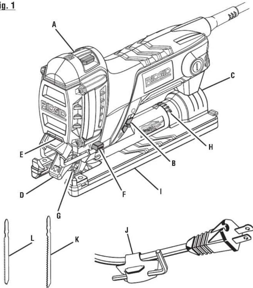
See Figure 1, page 13.
The safe use of this product requires an understanding of the information on the tool and in this operator's manual as well as a knowledge of the project you are attempting. Before use of this product, familiarize yourself with all operating features and safety rules.
BEVELING BASE
The base can be angled 45^ left or right for a bevel cut.
BLOWER/VACUUM SWITCH
The jig saw is equipped with a convenient switch for managing dust while cutting. First setting blows air to clean line-of-sight while cutting. Second setting turns off air to the line-of-sight air vent to allow the dust to be vacuumed up through the rear dust port.
HEX KEY STORAGE
A hex key has been provided for use in loosening and adjusting no-mar base plate. When not in use it can stored in the hex key strap.
LED LIGHT
The LED light, located above the blade clamp, illuminates when the switch is turned on. This provides extra light in the cutting area for increased visibility.
Input ......120 V, AC Only, 60 Hz, 3.0 Amp
Weight 4.4 lbs.
NO-MAR BASE PLATE
A no-mar base plate has been included with the jig saw. The plate protects delicate surfaces from being scratched by the metal jig saw base.
ORBITAL FUNCTION WITH ON/OFF SWITCH
The orbital function on/off switch allows user control of the orbital movement of the saw blade.
OVERMOLD GRIP AREA
The grip area is overmold for improved grip and comfort.
RAPID CHANGE BLADE CLAMP
The rapid change blade clamp allows for changing saw blades without the need for separate tools.
RECESSED BLADE SUPPORT ROLLER
The recessed blade support roller ensures accurate cutting during orbital and non-orbital cutting.
SLIDE SWITCH
The slide switch features a soft start to prolong motor life and gives the operator more control when starting the jig saw.
VACUUM PORT
1-1/4 in. vacuum port conveniently fits a standard hose size for a cleaner work area.
UNPACKING
This product has been shipped completely assembled.
- Carefully remove the product and any accessories from the box. Make sure that all items listed in the packing list are included.

WARNING:
Do not use this product if it is not completely assembled or if any parts appear to be missing or damaged. Use of a product that is not properly and completely assembled could result in serious personal injury.
■ Inspect the product carefully to make sure no breakage or damage occurred during shipping.
■ Do not discard the packing material until you have carefully inspected and satisfactorily operated the product.
■ If any parts are damaged or missing, please call 1-866-539-1710 for assistance.
PACKING LIST
Jig Saw
T-Shank Blades (1 - wood, 1 - metal)
Hex Key
Tool Bag
Operator's Manual

WARNING:
If any parts are damaged or missing do not operate this product until the parts are replaced. Use of this product with damaged or missing parts could result in serious personal injury.

WARNING:
Do not attempt to modify this product or create accessories not recommended for use with this product. Any such alteration or modification is misuse and could result in a hazardous condition leading to possible serious personal injury.

WARNING:
Do not connect to power supply until assembly is complete. Failure to comply could result in accidental starting and possible serious personal injury.
OPERATION

WARNING:
Do not allow familiarity with this product to make you careless. Remember that a careless fraction of a second is sufficient to inflict severe injury.

WARNING:
Always wear eye protection with side shields marked to comply with ANSI Z87.1. Failure to do so could result in objects being thrown into your eyes resulting in possible serious injury.

WARNING:
Do not use any attachments or accessories not recommended by the manufacturer of this tool. The use of attachments or accessories not recommended can result in serious personal injury.

WARNING:
To avoid possible serious injury, keep hands and fingers away from the area between the gear housing and saw blade clamp.
APPLICATIONS
You may use this product for the purpose listed below:
■ Sawing non-ferrous metal, sheet steel, wood, plastic, and similar materials.
STARTING/STOPPING THE SAW
See Figure 2, page 13.

WARNING:
Before connecting your jig saw to a power supply, always turn the jig saw off. Failure to do so could result in accidental starting resulting in serious personal injury.
■ To turn the jig saw ON, push the slide switch to the LEFT or ON (I) position.
NOTE: The saw has a soft start feature. The jig saw will start at a slow speed and gradually get up to full speed.
■ To turn the jig saw OFF, push the slide switch to the RIGHT OFF (O) position.
NOTE: Slide switch can be turned off with opposite hand, while maintaining grip with your primary hand.
LED LIGHT
See Figure 2, page 13.
The LED light illuminates when the slide switch is in the ON (I) position to give you a clear view of the cut line on your work surface.
ORBITAL FUNCTION WITH ON/OFF SWITCH
See Figure 3, page 13.
This feature can be turned on and off. Orbital function provides faster, more efficient cutting. With orbital function, the blade cuts through your work in the upstroke but does not drag across your work in the downstroke.
■ Unplug the saw.
- Push switch end with orbital symbol () left to turn on orbital function.
■ Push switch with non-orbital symbol ( ) right to turn orbital function off.
BLOWER/VACUUM MODE
See Figures 4 - 5, pages 13 - 14.
For dustless operation, the saw can be operated in either blower mode to clear dust from cutting area or vacuum mode to collect dust.
To operate in dust blower mode:
■ Unplug the saw.
■ Push blower/vacuum switch DOWN for blower mode. Dust will be blown from line of cut.
To operate in vacuum mode:
■ Unplug the saw.
■ Push blower/vacuum switch UP to vacuum position.
■ Attach a 1 1/4 in. diameter vacuum adapter inside the vacuum port at rear of saw.
- Plug in saw.
■ Turn on vacuum.
■ Begin cutting.
INSTALLING JIG SAW BLADES
See Figure 6, page 14.
■ Unplug the saw.
■ Lift the rapid change blade clamp lever until it stops.
■ Holding the rapid change blade clamp lever up, insert the saw blade as far as possible into the slot in the blade clamp body and roller blade support.
- Check to make sure the back of the saw blade is centered in the groove of the blade clamp body and roller blade support.
■ Release the rapid change blade clamp lever. Make sure the blade is securely in place.
REMOVING JIG SAW BLADES
See Figure 6, page 14.
■ Unplug the saw.
■ Allow blade to cool.
■ Lift the rapid change blade clamp until it stops.
■ Holding the rapid change blade clamp up, remove the saw blade.
NOTE: The jig saw is designed to use T-shank and U-shank blades.
NOTE: If blade becomes jammed, a light tap on the end of the blade with a block of wood while holding the blade clamp lever up, will release the blade.
GENERAL CUTTING
See Figure 7, page 14.
Rest the front of the saw base on the workpiece and align cutting edge of the blade with the line on the workpiece. Make sure the power cord is out of your way and not in the line of cut. Start your saw and move it forward on the work surface. Apply downward pressure to keep the saw steady and only enough forward pressure to keep the blade cutting.

CAUTION:
Do not force the saw. Forcing the saw may overheat the motor and break saw blades. Use clamps or another practical way to secure and support the workpiece to a stable platform.
STRAIGHT CUTTING
See Figure 8, page 14.
A straight cut can be made by clamping a piece of wood or straight edge to the workpiece and guiding the edge of the saw against it. Make the cut from one direction only. Don't cut halfway and complete the cut from the opposite end.
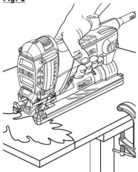
SCROLL CUTTING
See Figure 9, page 14.
Scroll cuts can be made with the saw by guiding the direction of the cut with applied pressure on the saw as shown.
NOTE: Works best with blades designed specifically for scroll cutting.

CAUTION:
Excessive side pressure to the blade could result in broken blades or damage to the material being cut.
BEVEL CUTTING
See Figures 10 - 11 page 14.
Bevel cutting angles may be adjusted from 0^ to 45^ right or left. Angles for cuts from 0^ to 45^ in 15^ increments are marked on a scale under the motor assembly. An arrow under the motor assembly provides an indicator at each of the 15^ increments. A protractor is recommended for making accurate cuts.
■ Unplug the saw.
■ Unlock the base by inserting the hex key into base adjustment screw located on bottom of saw and turning counter-clockwise to loosen.
■ Rotate base to desired angle.
■ Once the desired angle is reached, tighten by inserting the hex key into base adjustment screw and turning clockwise.
NOTE: If edge guide wing screw blocks desired angle, move screw to hole on other side of base plate.
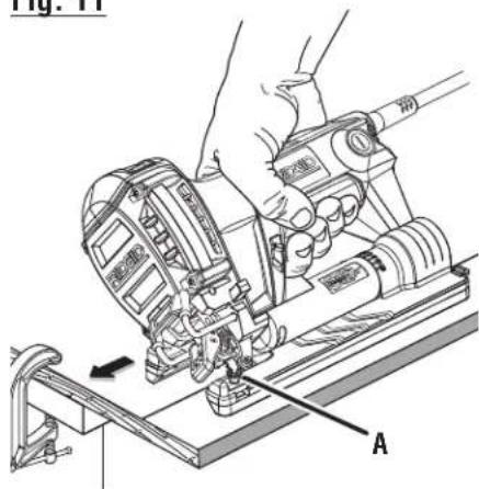
PLUNGE CUTTING
See Figure 12, page 15.

WARNING:
To avoid loss of control, broken blades, or damage to the material being cut, always use extreme caution when making plunge cuts. It is not recommended to plunge cut materials other than wood.
■ Mark the line of cut clearly on the workpiece.
■ Tilt the saw forward so that it rests on the front edge of the base and blade will not come in contact with the workpiece when the saw is turned on.
■ Make sure the blade is inside the area to be cut.
■ Start the saw and slowly lower the blade into the workpiece until the blade cuts through the wood.
■ Continue lowering the blade into the workpiece until the base rests flat on the work surface, then move the saw forward to complete the opening.
■ Use only the 7 teeth per inch blade for this type of cut.
METAL CUTTING
See Figure 13, page 15.
NOTE: Orbital mode should be OFF for metal cutting.
Many kinds of metals can be cut with the saw. Be careful not to twist or bend the blades. Do not force. If the blade chatters or vibrates excessively, use a finer-tooth metal-cutting blade. If blade heats excessively, reduce push force. If blade teeth become filled or clogged when cutting soft metals, such as aluminum, use a coarser-tooth blade or reduce push force. We recommend use of oil when cutting metals to keep blades cool, increase cutting action, and prolong blade life. Clamp the work firmly and saw close to the clamping point to eliminate any vibration of the work being cut.
When cutting conduit, pipe, or angle iron, clamp work in a vise if possible and saw close to the vise. To cut thin sheet materials, "sandwich" the material between hardboard or plywood and clamp the layers to eliminate vibration and material tearing. By doing this, the material will be cut smoothly. Lay out your pattern or line of cut on top of the "sandwich."
NOTE: When cutting metal, keep exposed portion of saw blade clean and free of metal chips by wiping frequently with an oily cloth. Use extreme caution in disposing of oily cloth after completion of job to prevent potential fire hazard.
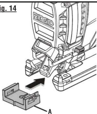
OPTIONAL ANTI-SPLINTERING INSERT (NOT INCLUDED)
See Figure 14, page 15.
An anti-splintering insert (not included) is especially useful when cutting plywood. It should only be used when making straight cuts or circle cuts. It is not for bevel cutting or plunge cutting.
NOTE: The non-orbital setting also helps reduce splintering when cutting plywood.
To attach and remove the anti-splintering insert:
■ Unplug the saw.
■ Set the cutting angle at 0^ .
■ To attach, slide the insert back onto the tabs on the front of the shoe. Make sure it snaps securely into place.
■ To remove, grasp the anti-splintering insert and pull straight out.
- Plug in saw.
OPTIONAL EDGE GUIDE (NOT INCLUDED)
See Figure 15, page 15.
An optional edge guide is available for use with the saw. It can be used for making cross cuts and rip cuts.
■ Unplug the saw.
- Insert the arm through the two slots in the base of the saw as shown.
■ Adjust edge guide to the desired width and lock in place with the edge guide wing screw.
- Plug in saw.

WARNING:
When servicing use only identical RIDGID replacement parts. Use of any other parts may create a hazard or cause product damage.

WARNING:
Always wear eye protection with side shields marked to comply with ANSI Z87.1. Failure to do so could result in objects being thrown into your eyes resulting in possible serious injury.
GENERAL MAINTENANCE
Avoid using solvents when cleaning plastic parts. Most plastics are susceptible to damage from various types of commercial solvents and may be damaged by their use. Use clean cloths to remove dirt, dust, oil, grease, etc.

WARNING:
Do not at any time let brake fluids, gasoline, petroleum-based products, penetrating oils, etc., come in contact with plastic parts. Chemicals can damage, weaken or destroy plastic which may result in serious personal injury.
Electric tools used on fiberglass material, wallboard, spackling compounds, or plaster are subject to accelerated wear and possible premature failure because the fiberglass chips and grindings are highly abrasive to bearings, brushes, commutators, etc. Consequently, we do not recommend using this tool for extended work on these types of materials. However, if you do work with any of these materials, it is extremely important to clean the tool using compressed air.
LUBRICATION
All of the bearings in this product are lubricated with a sufficient amount of high grade lubricant for the life of the unit under normal operating conditions. Therefore, no further lubrication is required.
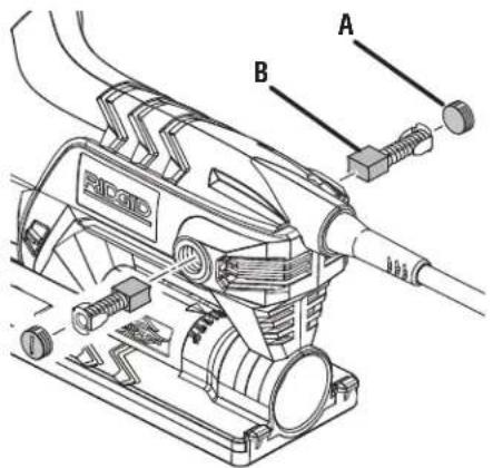
CHECKING/REPLACING EXTERNAL BRUSHES
See Figure 16, page 15.
NOTE: The saw is equipped with externally accessible brushes.
■ Unplug the saw.
NOTE: Brush caps are located on each side of the motor housing.
■ Remove brush caps using a screwdriver.
■ Remove brush assemblies.
- Check for wear. Replace both brush assemblies when either has less than 1/4 in. length of carbon remaining.
NOTE: Do not replace one side without replacing the other.
■ Reassemble using new brush assemblies. Make sure curvature of brush matches curvature of motor and that brush moves freely in brush tube.
■ Reassemble by reversing the steps listed above.
■ Tighten all brush caps securely. Do not over tighten.
ACCESSORIES
Look for these accessories where you purchased this product:
■ Edge Guide Kit....201754003
■ Anti-Splintering Insert 521976001

WARNING:
Current attachments and accessories available for use with this tool are listed above. Do not use any attachments or accessories not recommended by the manufacturer of this tool. The use of attachments or accessories not recommended can result in serious personal injury.
NOTE: FIGURES (ILLUSTRATIONS) START ON PAGE 13 AFTER FRENCH AND SPANISH LANGUAGE SECTIONS.
RIDGID® HAND HELD AND STATIONARY POWER TOOL 3 YEAR LIMITED SERVICE WARRANTY
Proof of purchase must be presented when requesting warranty service.
Limited to RIDGID® hand held and stationary power tools purchased 2/1/04 and after. This product is manufactured by One World Technologies, Inc. The trademark is licensed from RIDGID, Inc. All warranty communications should be directed to One World Technologies, Inc., attn: RIDGID Hand Held and Stationary Power Tool Technical Service at (toll free) 1-866-539-1710.
90-DAY SATISFACTION GUARANTEE POLICY
During the first 90 days after the date of purchase, if you are dissatisfied with the performance of this RIDGID® Hand Held and Stationary Power Tool for any reason you may return the tool to the dealer from which it was purchased for a full refund or exchange. To receive a replacement tool you must present proof of purchase and return all original equipment packaged with the original product. The replacement tool will be covered by the limited warranty for the balance of the 3 YEAR service warranty period.
WHAT IS COVERED UNDER THE 3 YEAR LIMITED SERVICE WARRANTY
This warranty on RIDGID® Hand Held and Stationary Power Tools covers all defects in workmanship or materials and normal wear items such as brushes, chucks, motors, switches, cords, gears and even cordless batteries in this RIDGID® tool for three years following the purchase date of the tool. Warranties for other RIDGID® products may vary.
HOW TO OBTAIN SERVICE
To obtain service for this RIDGID® tool you must return it; freight prepaid, or take it in to an authorized service center for RIDGID® branded hand held and stationary power tools. You may obtain the location of the authorized service center nearest you by calling (toll free) 1-866-539-1710 or by logging on to the RIDGID® website at www.ridgid.com. When requesting warranty service, you must present the original dated sales receipt. The authorized service center will repair any faulty workmanship, and either repair or replace any part covered under the warranty, at our option, at no charge to you.
WHAT IS NOT COVERED
This warranty applies only to the original purchaser at retail and may not be transferred. This warranty only covers defects arising under normal usage and does not cover any malfunction, failure or defect resulting from misuse, abuse, neglect, alteration, modification or repair by other than an authorized service center for RIDGID® branded hand held and stationary power tools. Consumable accessories provided with the tool such as, but not limited to, blades, bits and sand paper are not covered.
RIDGID, INC. AND ONE WORLD TECHNOLOGIES, INC. MAKE NO WARRANTIES, REPRESENTATIONS OR PROMISES AS TO THE QUALITY OR PERFORMANCE OF ITS POWER TOOLS OTHER THAN THOSE SPECIFICALLY STATED IN THIS WARRANTY.
ADDITIONAL LIMITATIONS
To the extent permitted by applicable law, all implied warranties, including warranties of MERCHANTABILITY or FITNESS FOR A PARTICULAR PURPOSE, are disclaimed. Any implied warranties, including warranties of merchantability or fitness for a particular purpose, that cannot be disclaimed under state law are limited to three years from the date of purchase. One World Technologies, Inc. and RIDGID, Inc. are not responsible for direct, indirect, incidental or consequential damages. Some states do not allow limitations on how long an implied warranty lasts and/or do not allow the exclusion or limitation of incidental or consequential damages, so the above limitations may not apply to you. This warranty gives you specific legal rights, and you may also have other rights which vary from state to state.
One World Technologies, Inc.
P.O. Box 35, Hwy. 8
Pickens, SC 29671
AVERTISSEMENTS GÉNÉRAUX ET INSTRUCTIONS GÉNÉRALES DE SÉCURITÉ EN CE QUI A TRAIT AUX OUTILS ÉLECTRIQUES

AVERTISSEMENT !
COUPE SANS ÉCLATEMENT (NON INCLUS)
Voir la figure 14, page 15.
GUIDE DE CHANT EN OPTION (NON INCLUS)
Voir la figure 15, page 15.
RÉPARATIONS SOUS GARANTIE
One World Technologies, Inc.
P.O. Box 35, Hwy. 8
Pickens, SC 29671, ÉTATS-UNIS
0-2,0 2,1-3,4 3,5-5,0 5,1-7,0 7,1-12,0 12,1-16,0
| Longitud del cordón | Calibre conductores (A.W.G.) | ||||
| 25' | 16 | 16 | 16 | 16 | 14 |
| 50' | 16 | 16 | 16 | 14 | 14 |
| 100' | 16 | 16 | 14 | 12 | 10 |
One World Technologies, Inc.
P.O. Box 35, Hwy. 8
Pickens, SC 29671, USA
Fig. 1
text_image
g. 1 A C RIDGD E D G F I H B K L Jnatural_image
Illustration of hands operating a precision machine on a workbench, no text or symbols presentFig. 9
natural_image
Line drawing of a hand operating a power tool on a workbench (no text or symbols)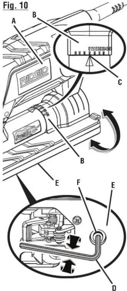
text_image
Fig. 10 A B RIDGID 0151530304545 C B E F E DA - Motor housing (boîtier du moteur, alojamiento del motor)
B - Bevel scale (échelle de biseau, escala de bisel)
C - Arrow (flèche, flecha)
D - Hex key (clé hex, llave hexagonal)
E - No-mar base plate (plaque de protection, placa protectora de la base)
F - Base adjustment screw(vis de réglage de la base, tornillo de ajuste de la base)
Fig. 11
text_image
Fig. 11 Anatural_image
Illustration of a hand using a tool to adjust or install a mechanical component, with no visible text or symbols.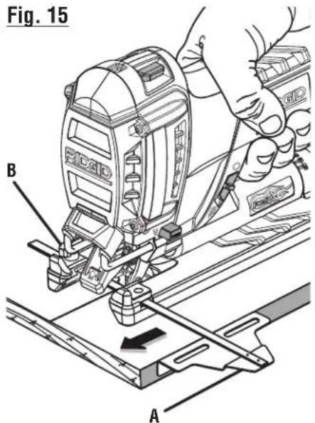
text_image
Fig. 15 B A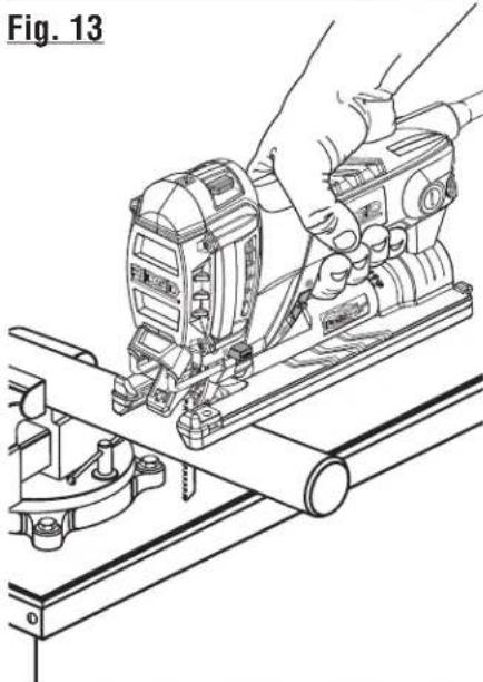
natural_image
Line drawing of hands operating a mechanical device with tools and components (no text or symbols)A - Optional edge guide kit (ensemble de guide de chant option, juego de guías para cantos optativa)
B - Optional wing screw (vis à oreilles en option, tornillo de mariposa optativa)
Fig. 16
text_image
Technical diagram of a mechanical device with labeled parts A and B, showing internal components and assembly.Fig. 14
text_image
g. 14 RIGID AA - Brush cap (couvercle de balai, tapa de la escobilla)
B - Brush assembly (balai, conjunto de la escobilla)
A - Optional anti-splinter insert (garde anti-éclatement en option, protección anti-astillamiento)
OPERATOR'S MANUAL
MANUEL D'UTILISATION
MANUAL DEL OPERADOR
COMPACT JIG SAW
SCIE SAUTEUSE COMPACTE
Customer Service Information:
For parts or service, contact your nearest RIDGID® authorized service center. Be sure to provide all relevant information when you call or visit. For the location of the authorized service center nearest you, please call 1-866-539-1710 or visit us online at www.ridgid.com.
The model number of this tool is found on a plate attached to the motor housing. Please record the serial number in the space provided below. When ordering repair parts, always give the following information:
Model No. R3101
Serial No. ____