
JARO 3050 T - Lamp BRENNENSTUHL - Free user manual and instructions
Find the device manual for free JARO 3050 T BRENNENSTUHL in PDF.

| Product type | LED floodlight with infrared motion detector |
| Brand | Brennenstuhl |
| Model | JARO 3050 T |
| Rated voltage | 220-240 V ~ 50/60 Hz |
| Protection rating | IP54 (version with motion detector) |
| Impact resistance | IK08 |
| Ambient temperature | -20 °C to +50 °C |
| Max installation height | 3 m (recommended 2.5 m with detector) |
| Detector type | Passive infrared sensor (PIR) |
| Detection range | Up to 10 m (depending on installation) |
| Detection angle | 120° horizontal |
| Lighting duration setting | 10 seconds to 5 minutes |
| Brightness threshold setting | 0 to 2000 lux |
| Sensitivity adjustment | Variable (- to +) |
| Light source | Non-replaceable LED |
| Power | 10-50 W (version without detector) / 80-150 W (version with detector) |
| Power supply | Mains |
| Usage | Indoor and outdoor |
| Maintenance and cleaning | Disconnect before cleaning; use a dry or slightly damp cloth; no solvents |
| Safety instructions | Do not open; do not use with external dimmer; do not look directly at the beam; non-replaceable cable |
| Repairability | No replaceable parts; replace entire unit at end of life |
Frequently Asked Questions - JARO 3050 T BRENNENSTUHL
User questions about JARO 3050 T BRENNENSTUHL
0 question about this device. Answer the ones you know or ask your own.
Ask a new question about this device
Download the instructions for your Lamp in PDF format for free! Find your manual JARO 3050 T - BRENNENSTUHL and take your electronic device back in hand. On this page are published all the documents necessary for the use of your device. JARO 3050 T by BRENNENSTUHL.
USER MANUAL JARO 3050 T BRENNENSTUHL
LED Light with infrared motion detector
Projecteur LED
GB Operating instructions ....13
GB Installation instructions ..... 4-8
FR Manuel d'installation ..... 4-8
NL Montagehandleiding 4-8
natural_image
Technical illustration of two mechanical components with circular arrows indicating motion or assembly (no text or symbols)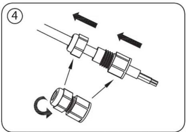
JARO 80/100 W
natural_image
Technical diagram of a mechanical assembly with no visible text or symbols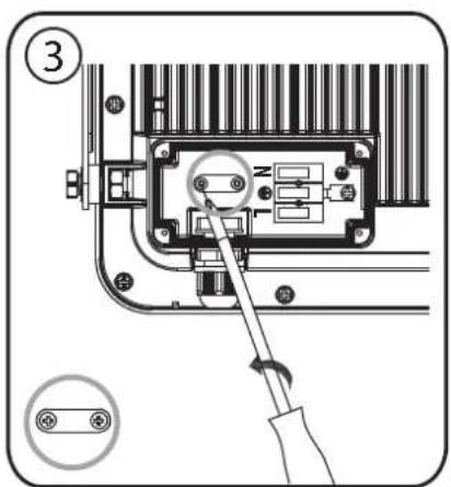
natural_image
Technical line drawing of a mechanical component with a grid pattern and a tool inserted (no text or symbols)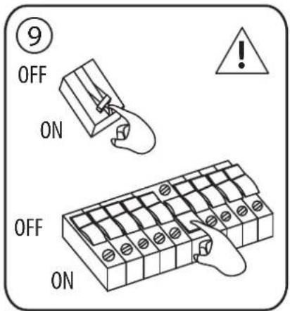
JARO 150 W
Montageanleitung Installation instructions Manuel d'installation Montagehandleiding Istruzioni per il montaggio Monteringsanvisning Instrucciones de instalación Instrukcja montażu Montážní návod Szerelési utasítás
Montaj talimati Asennusohje Οδηγίες εγκατάστασης Руководство по монтажу Instruções de instalação Paigaldusjuhend Montážny návod Navodila za montažo Montāžas instrukcija Montavimo instrukcija
natural_image
Technical diagram of a mechanical assembly with no visible text or symbols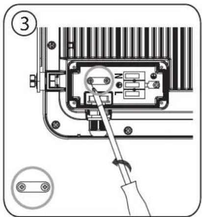
natural_image
Technical line drawing of a mechanical component with a grid pattern and screwdriver (no text or symbols)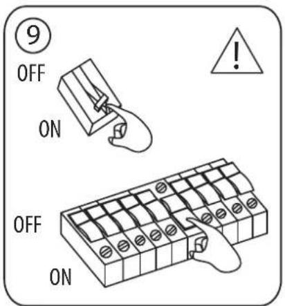
⑨
10
⑪
SENS
SENS
12
13

Bedienungsanleitung
LED Strahler
Operating Instructions
LED Light
LED Light with infrared motion detector
JARO
Attention: Before using the product, please carefully read the operating instructions and store them in a proper location!
SAFETY INSTRUCTIONS
- Always check the product for damage before use. Never use the product in case of any damage. If this is the case, please refer to an electrician or the manufacturer's service address.

Non-compliance poses a risk of fatal injury from electrical current!
- Do not use the product in potentially explosive atmospheres – danger of death!
- Keep the floodlight away from children. Children are not aware of the risks imposed by electric current.
- Please never look directly into the light.
- A destroyed protective cover cannot be replaced. The floodlight has to be disposed of.
-
The external flexible cable of this lamp cannot be exchanged; if the cable is damaged, the lamp has to be scrapped.
-
The following applies to the JARO 7050, 9050, 13050 floodlights:

Hot surface

Not suitable for applications with external dimmers.

If the minimum distance is not complied with, illuminated objects may overheat.
TECHNICAL DATA
Protection class: I
Protection type/impact resistance
(versions without motion detector): IP65, IK08
Protection type/impact resistance
(versions with motion detector): IP54, IK08
Nominal voltage: 220-240 V\~ 50/60 Hz
Temperature range: -20 °C to +50 °C
This product is suitable for indoor and outdoor lighting purposes.
INSTALLATION AND CONNECTION TO POWER SUPPLY 10 - 50 W
see figures p. 4, 7 and 8
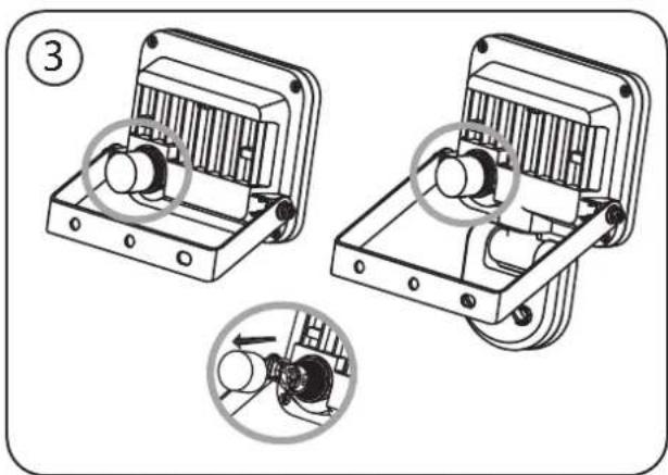
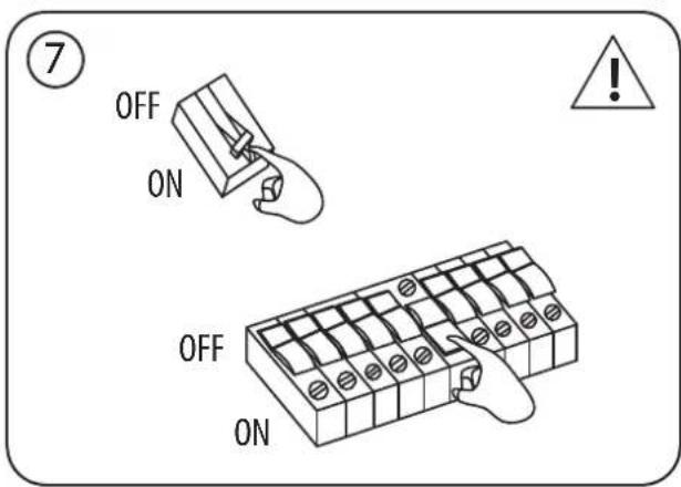
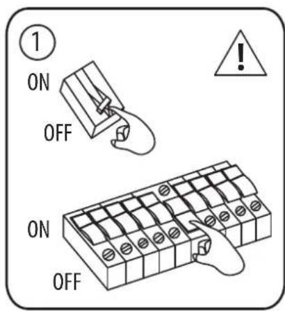
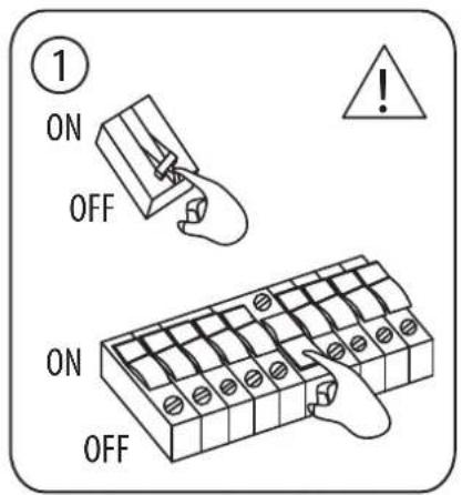
- Before installation, always switch off the voltage supply ①.
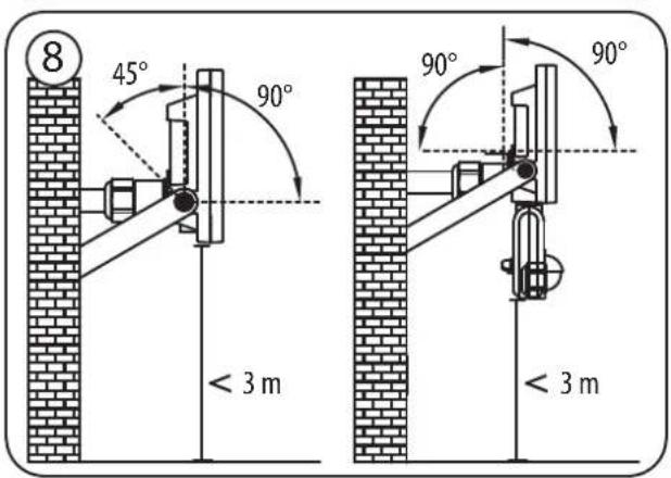
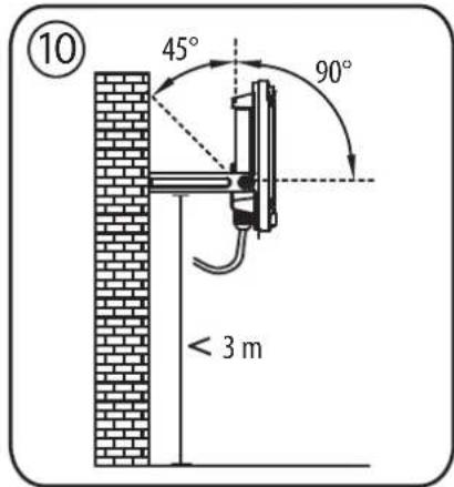
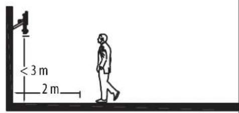
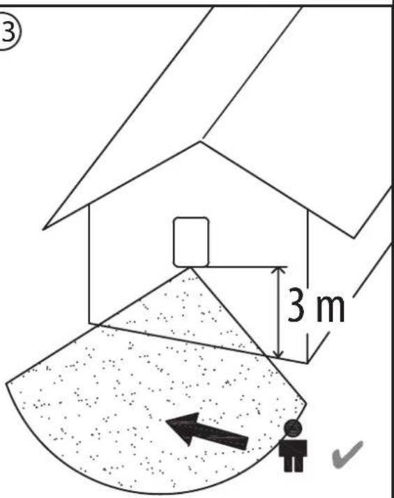
- Installation position: the floodlight should ideally be mounted using the wall bracket. The floodlight must be installed at a height of less than 3 m ⑧. Recommended installation height for models with motion detector 2.5 m. The floodlight can be angled up and down.
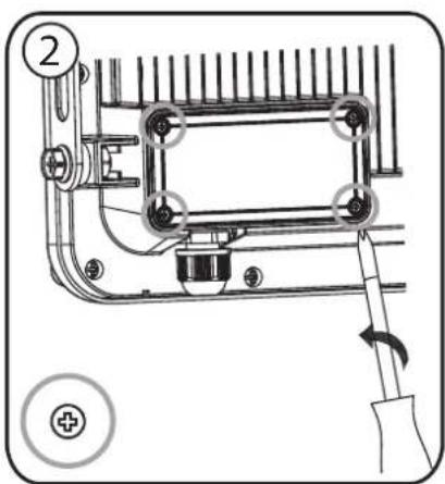
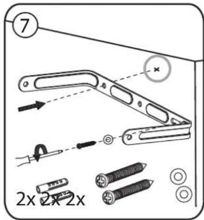
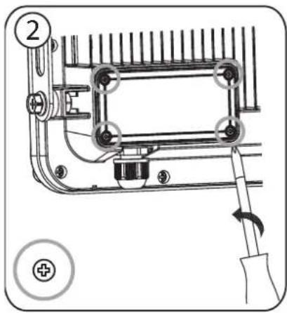
- Remove the mounting bracket from the floodlight ②.
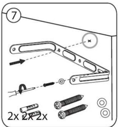
- Mark the position of the drill holes for fastening the mounting bracket and drill corresponding holes into the wall ②. Attach the bracket to the wall using suitable screws.
- Open the plug connection ③.
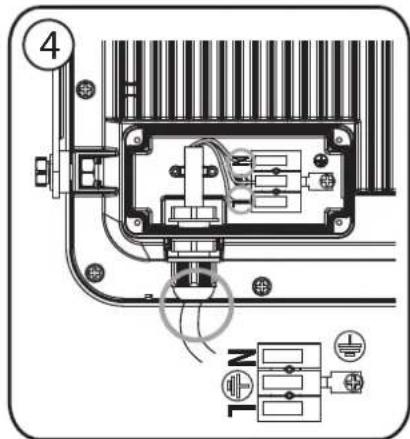
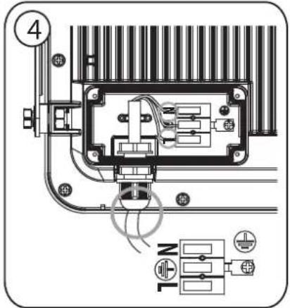
- Feed the connection cable through the plug sleeve, which has a seal ④.
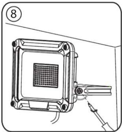
- Attach the floodlight to the mounting bracket.
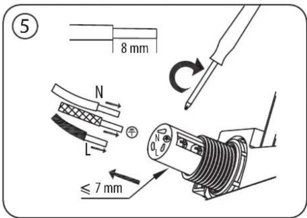
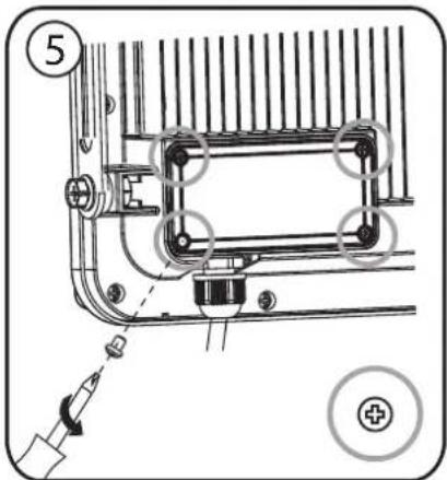
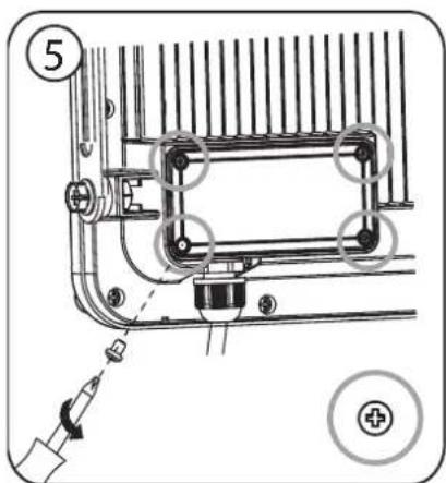
- Connect the strands of the connection cable to the luster terminal in the input connector in accordance with ⑤ (N = blue cable, earth symbol = green/yellow cable, L = brown cable).
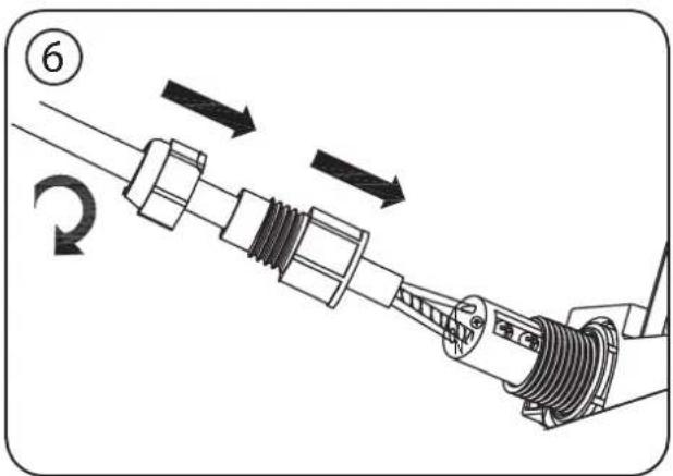
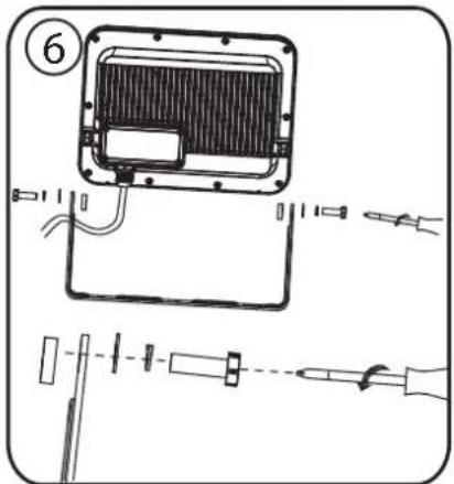
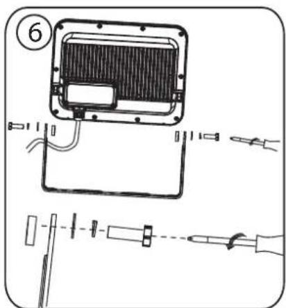
- Slide the cases over the input connector as shown in ⑥ and tighten it. Take care to ensure that both cases are sufficiently tightened – this ensures a sufficient seal.
- Re-attach the mounting bracket to the floodlight.
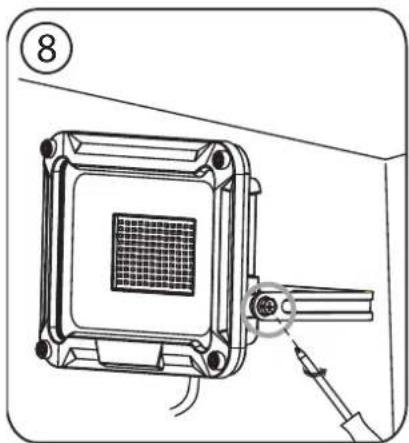
- Adjust the desired position of the floodlight and fasten the U bolts.
- Switch the supply voltage back on ⑦.
INSTALLATION AND CONNECTION TO POWER SUPPLY 80 - 150 W
see figures p. 5 and 6
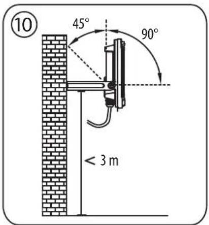
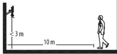
Mounting position: The spotlight should be ideally fixed with the wall bracket. It must be installed at a height less than 3 m ⑩.
The light can be tilted by 90^ downwards and by 45^ upwards ^⑩ .
- Always turn off the power supply before installation ①.
- Unscrew the junction box ② on the back and loosen the pressure plate ③.
- Insert the connection cable ④ through the inlet pipe of the junction box and connect the braids of the connection cable according to marking N and L ④.
- Fasten the pressure plate and screw the junction box on ⑤.
- Remove the retaining bracket from the spotlight ⑥.
- Mark the position of boreholes ⑦ for securing the retaining bracket and drill the respective holes on the wall. Attach the bracket to the wall with suitable screws ⑦.
- Secure the spotlight to the retaining bracket ⑧.
- Adjust the desired position of the spotlight and tighten the U-bolts ⑧.
- Turn the power supply back on ⑨.
FUNCTIONAL DESCRIPTION
(only for versions with motion sensor)
This floodlight is equipped with an infrared sensor. It is switched on automatically if the sensor detects motion in the environment.
If possible, do not direct the motion sensor at swimming pools, heating air exhausts, air conditioning units or objects which are exposed to major temperature fluctuations.
Avoid directing the motion sensor at trees or bushes or at places which could be frequently visited by pets.
The motion sensor can be turned horizontally to the right and left and angled vertically up and down.
When mounting the floodlight remember that the motion sensor will react most sensitively to motions crossing its field of detection from one side to the other and least sensitively to motions directly approaching the unit.
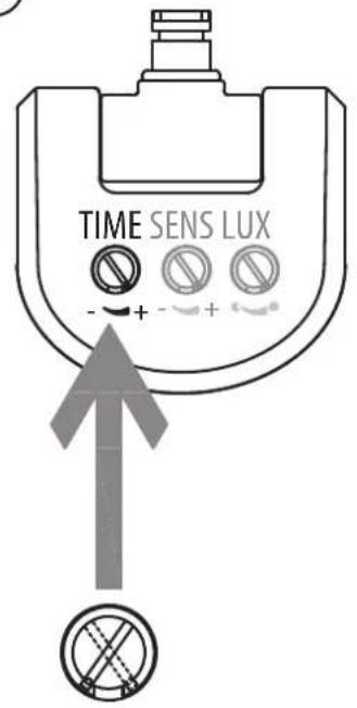
CONFIGURING THE MOTION DETECTOR (PIR)
Three controllers are located on the rear of the motion detector ⑨.
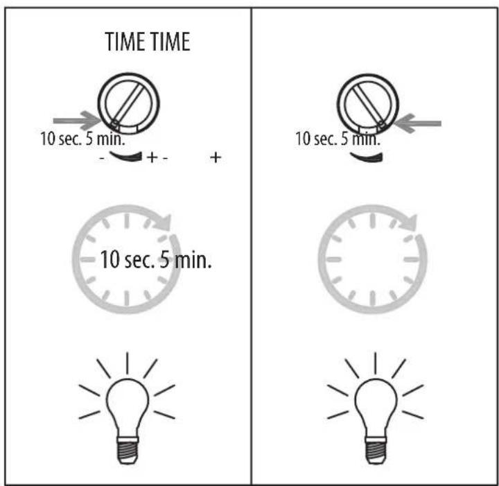
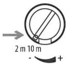
TIME - time adjustment (left):
Using this controller, you can select any switch-on time between approx. 10 seconds and 5 minutes after the last motion was detected. Rotating the TIME controller clockwise decreases the time period, rotating it counterclockwise increases it.
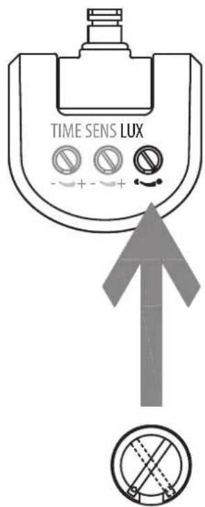
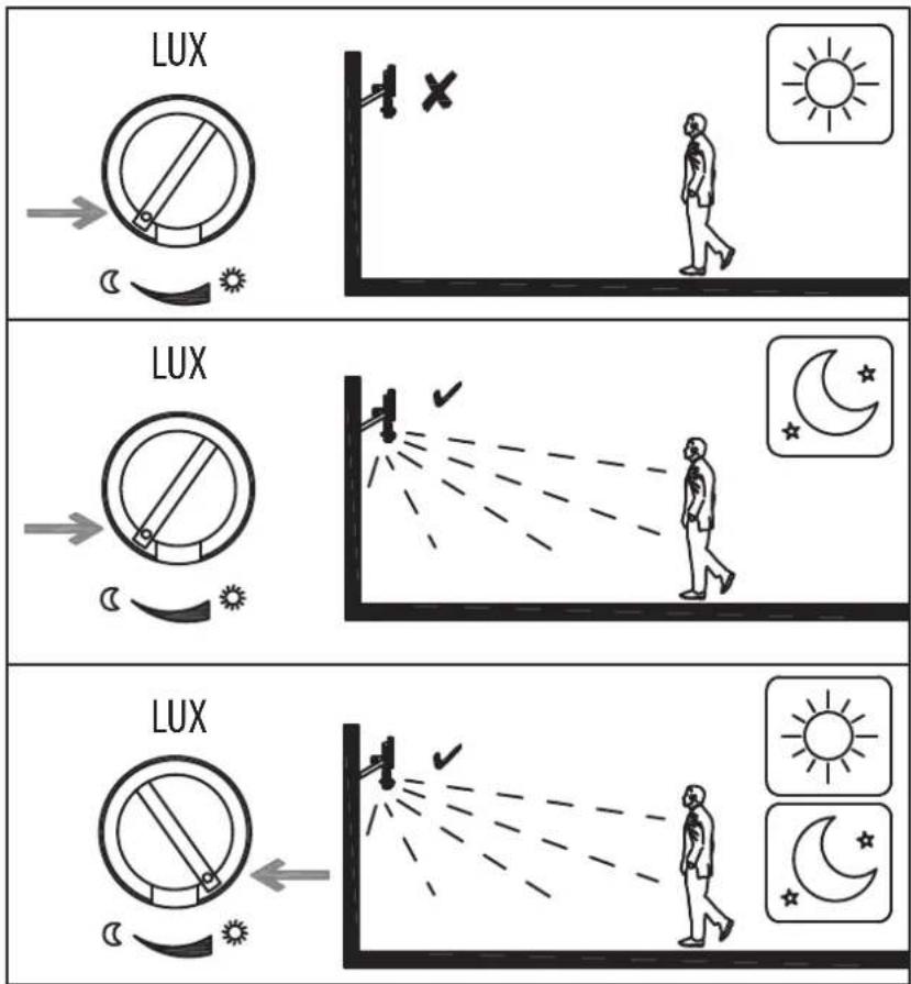
LUX – light adjustment (sun and moon symbol, right) ⑩:
The light adjustment determines from what brightness level the sensor will switch on the floodlight.
The (sun symbol) position indicates that the sensor works by day and at night, in the (moon symbol) position, the sensor will only work at night. To adjust the sensor, wait until the desired ambient brightness is reached. Completely rotate the light adjustment controller to the (moon) symbol. Slowly rotate the controller in the direction of the (sun) symbol until the floodlight is switched on by the motion.
The floodlight will now be activated from the set brightness when a motion is detected.
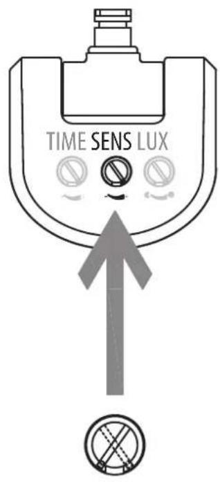
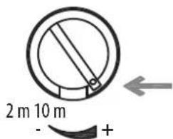
SENS - SENSITIVITY ADJUSTMENT (CENTRE) ⑪:
The sensitivity of the sensor depends on the ambient temperature. The lower the ambient temperature, the greater the sensitivity of the motion detector.
The sensor is at its most sensitive when the SENS controller is turned all the way to the (+) direction.
Motion sensor: passive infrared sensor (PIR)
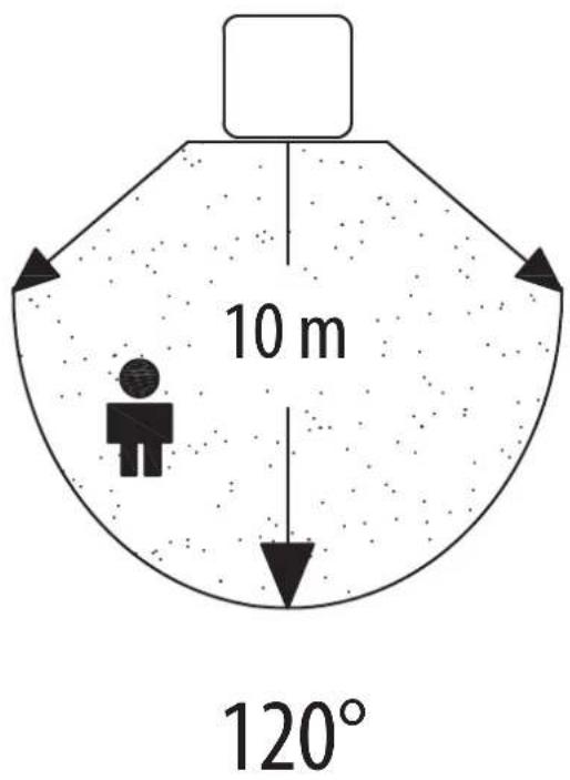
Detection range: up to 10 m/up to 120° (horizontal) ⑫
Time adjustment: approx. 10 sec. to 5 min.
Ambient brightness: 0 – 2000 lux
Sensitivity: 3 to 10 m depending on the installation location ⑬
MAINTENANCE
ATTENTION! The LED lamp does not contain components that require maintenance. The light source in this lamp cannot be replaced; if the light source has reached the end of its service life, the entire lamp has to be replaced. The lamp may not be opened.
CLEANING
Before cleaning, disconnect the floodlight from the mains power.
Do not use solvents, caustic cleaning agents or similar products. Only use a dry or slightly moistened cloth for cleaning.
DISPOSAL
Dispose of electric appliances in an environmentally friendly manner! Electric appliances must not be disposed of in household waste!
The European Directive 2012/19/EU on Waste Electrical and Electronic Equipment rules that used electric appliances should be collected separately and recycled in an environmentally friendly manner.
For possibilities of disposal of the used appliance, please contact your local or municipal administration.

EU DECLARATION OF CONFORMITY

UK DECLARATION OF CONFORMITY
The declaration of conformity is deposited at the manufacturer.
ADRESSES
For more information please visit the Service/FAQ section on our homepage, www.brennenstuhl.com.

Mode d'emploi
Projecteur LED
DÉCLARATION DE CONFORMITÉ UE