
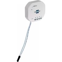
BrematicPRO APWT868 01 IP44 - Smart Home BRENNENSTUHL - Free user manual and instructions
Find the device manual for free BrematicPRO APWT868 01 IP44 BRENNENSTUHL in PDF.

| Product type | Wireless wall switch |
| Brand | Brennenstuhl |
| Model | BrematicPRO APWT868 01 IP44 |
| Category | Smart home |
| Radio frequency | 868.3 MHz |
| Frequency band | 868.1 – 868.5 MHz |
| Max transmission power | < 20 mW |
| Duty cycle | < 1 % per hour |
| Power supply | 1 CR2450 3V button cell |
| Max current consumption | 30 mA |
| Battery life | Approx. 2 years (typ.) |
| Range in open area | Approx. 100 m |
| Protection rating | IP44 |
| Ambient temperature | 0°C to +35°C |
| Dimensions (W x H x D) | 79.3 x 79.3 x 17.4 mm |
| Weight | 54 g |
| Package contents | 1 wall switch, 1 CR2450 battery, mounting kit (screws/dowels, adhesive pad), quick start guide, digital manual |
| Main functions | Wireless control of BrematicPRO products, direct pairing or via Gateway, programming via app or PC software, two-touch toggle |
| Mounting | By screwing or gluing (adhesive pad included) |
| Cleaning | Dry, lint-free cloth, no solvents, do not immerse |
| Safety | Contains a lithium button cell (risk of ingestion), follow safety instructions, do not open the housing |
| Disposal | Device and batteries must not be disposed of with household waste, recycling according to Directive 2006/66/EC |
Frequently Asked Questions - BrematicPRO APWT868 01 IP44 BRENNENSTUHL
User questions about BrematicPRO APWT868 01 IP44 BRENNENSTUHL
0 question about this device. Answer the ones you know or ask your own.
Ask a new question about this device
Download the instructions for your Smart Home in PDF format for free! Find your manual BrematicPRO APWT868 01 IP44 - BRENNENSTUHL and take your electronic device back in hand. On this page are published all the documents necessary for the use of your device. BrematicPRO APWT868 01 IP44 by BRENNENSTUHL.
USER MANUAL BrematicPRO APWT868 01 IP44 BRENNENSTUHL
natural_image
Plain white square button with rounded corners, no text or symbols visible

Funk-Wandtaster
Bedienungsanleitung

Wireless Wall Switch
Instructions for use

Draadloze wandschakelaar
Gebruiksaanwijzing
natural_image
Technical line drawings of a device housing with internal components (no text or symbols)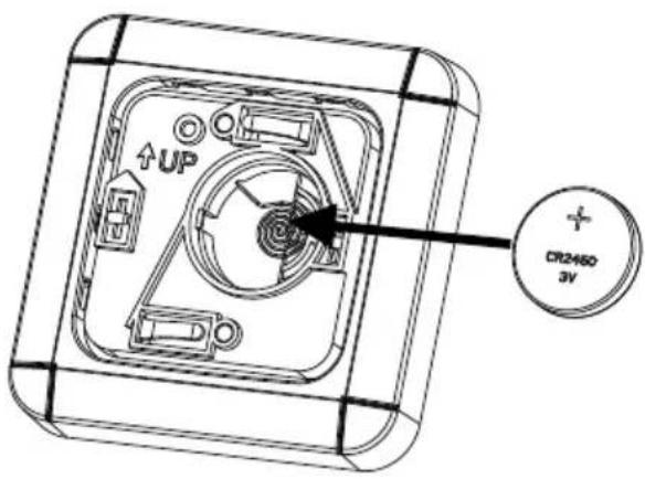
natural_image
Technical line drawings of a mechanical component assembly (no text or symbols)natural_image
Pure electrical circuit lines without any symbols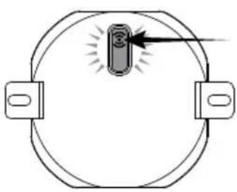
natural_image
Simple line drawing of a circular object with two side brackets and a central illuminated component, no text or symbols present.natural_image
Green gradient bar with no text or symbols
Wireless wall switch4 868.3 MHz
List of pictograms used....Page 12
Safety instructions Page 12
Special safety instructions for handling batteries....Page 12
Intended use....Page 13
Information about Wireless Operation Page 13
Duty Cycle....Page 13
Included in delivery Page 13
Technical data....Page 13
Device overview Page 14
Front Page 14
Back Page 14
Inside view Page 14
Function......Page 14
Preparation Page 14
Inserting / replacing the battery....Page 14
Installation Page 15
Installation using screws....Page 15
Installation using adhesive....Page 15
Download app / PC software BrematicPRO Page 16
Pairing the wireless wall switch directly with BrematicPRO devices....Page 16
Pairing the wireless wall switch with the BrematicPRO Gateway....Page 16
Cleaning the Device....Page 17
Action......Page 17
Disposal Page 17
Service Page 17
Manufacturer Page 17
Declaration of conformity....Page 17
| List of pictograms used | |||
 | Please read the instructions for use! Observe the warnings |  y instructions! y instructions! | |
 | Caution! Danger of explosion! Caution! Danger of electric s |  | |
 | Dispose of the packaging and device in an environ-mentally friendly manner! |  | Improper disposal of batteries can harm the environment! |
Safety instructions
The instructions for use are a part of this product.
They contain important information about safety, use and disposal. Before using this device, please familiarise yourself with all instructions for use and safety instructions. Only use the device as described and for the indicated purpose. Be sure to include all documentation when passing this device on to others.
WARNING! DANGER TO LIFE AND RISK OF ACCIDENTS FOR INFANTS AND CHILDREN! Never leave children alone and unsupervised with the packaging material. It poses a risk of suffocation as children may swallow or inhale small parts or plastic film. Children frequently underestimate the dangers. Always keep children away from the device. It is not a toy.
This device may be used by children aged 8 years and up, as well as by persons with reduced physical, sensory or mental capacities, or lacking experience and/or knowledge, so long as they are supervised or instructed in the safe use of the device and understand the associated risks. Do not allow children to play with the device. Cleaning and user maintenance must not be performed by children without supervision.
Operate the device protected from weather. Do not expose the device to adverse conditions, such as
- direct precipitation,
• excessive dust, - direct sunlight,
- vibrations.
- This device is suitable for outdoor use; it complies with protection type IP44.
CAUTION! RISK OF INJURY!
- Do not open the housing. This device has no parts which require maintenance.
- Do not use the device if it is visibly damaged.
We assume no liability for property damage or personal injury due to improper use or failure to observe the safety instructions! This will void the warranty/guarantee! - Any use not specified in these instructions for use will damage the device. Do not modify the device. Otherwise safe operation is not guaranteed.
- You will have to replace the device if water enters it.
Special safety instructions for handling batteries
WARNING! DANGER TO LIFE!
Batteries are not intended for children. Seek immediate medical attention if swallowed!
CAUTION! DANGER OF EXPLOSION! Never
recharge disposable batteries, do not short-circuit and / or open batteries!
● Never throw batteries into fire or water!
Do not exert mechanical loads on batteries!
Risk of battery leakage
In the event of a battery leak, immediately remove it from the device to prevent damage!
Avoid contact with the skin, eyes and mucous membranes! In the event of contact with battery acid, flush the affected areas with clean water and seek immediate medical attention!
- Avoid extreme conditions and temperatures which may affect batteries, e.g. radiators/direct sunlight.
- Remove the batteries from the device if they have not been used for a long period!
Risk of device damage
- Only use the specified battery type!
Please note the correct polarity when inserting the battery! - If necessary, clean the battery and device contacts before inserting the battery!
- Promptly remove drained batteries from the device!
WARNING! CHEMICAL BURNS!
Keep batteries away from children.
The device contains a lithium button cell. If a new or drained button cell is swallowed or enters the body it can lead to severe internal chemical burns and can cause death within two hours of ingestion. Always ensure that the battery compartment is securely shut. If the battery compartment does not close correctly, stop using the device, remove the battery and keep it away from children.
If you believe that a button cell has been swallowed or has entered someone's body, seek immediate medical attention.
The batteries must be disposed of correctly, even if they have been kept away from children.
- Even used batteries can cause injuries.
Intended use
This device is suitable for outdoor use; it complies with protection type IP44.
Information about Wireless Operation
This device uses the 868.3 MHz proprietary wireless protocol. Wireless transmission is implemented using a non-exclusive channel, interference can therefore not be excluded.
The range in buildings may vary greatly from open areas. In addition to the transmission power and the reception characteristics of the receivers, ambient conditions, e.g. humidity in addition to the structural conditions on site, are important factors.
The range can be significantly reduced in part due to:
- Wood, gypsum, concrete, reinforced concrete walls
• Proximity to metal and conductive objects - Broadband interference, e.g. in residential areas (DECT phones, mobiles, wireless headphones, wireless speakers, wireless weather stations, baby monitors)
- Proximity to electric motors, transformers, mains adapters, computers
Duty Cycle
Duty cycle refers to a transmission time limit regulated by law for devices transmitting in the 868 MHz range. It is intended to ensure smooth operation of devices operating in the 868 MHz range. The maximum transmission time of each device is 1% of an hour (corresponding to 36 seconds / hour). Once the 1% limit has been reached it cannot transmit until the time limit of the duty cycle has ended, so after one hour.
Included in delivery
1 x Wireless wall switch
1 x Button cell CR2450
1 x Installation kit (screws / dowels, adhesive pad)
1 x Quick start guide
1 x Instructions for use (digital, available for download)
Technical data
Product designation: APWT 868 01 IP44 3726
Item no.: 1294600
Radio frequency: 868.3 MHz
Frequency: 868.1 - 868.5 MHz
Max. transmitting power: < 20 mW
Duty cycle: < 1 % per h
Supply voltage: 1 x 3 V button cell CR2450
Power consumption: 30 mA max.
Battery life span: approx. 2 years (typically)
Ambient temperature: 0 °C to +35 °C
Protection type: IP44
Open area range: approx. 100 m
Dimensions (W x H x D): 79.3 x 79.3 x 17.4 mm
Weight: 54 g
Subject to technical changes without notice.
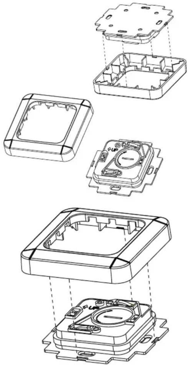
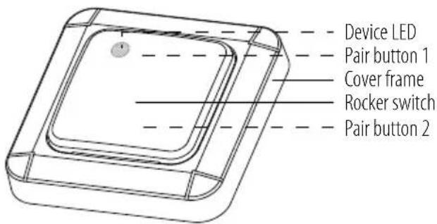
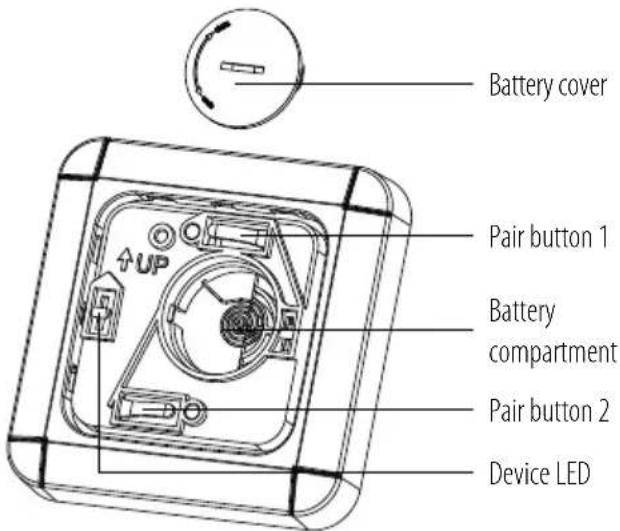
Device overview
Front
Back
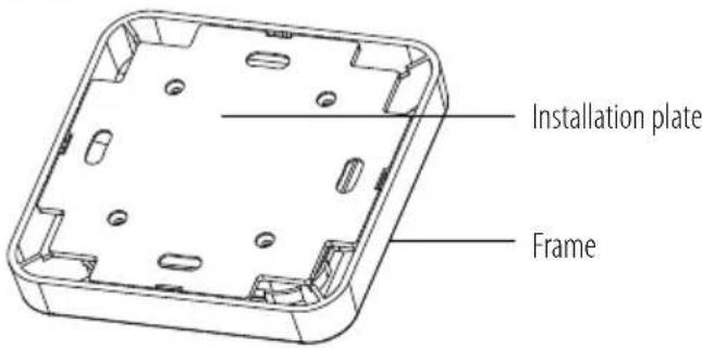
Inside view
Function
The wireless wall switch is part of the Brennenstuhl Home Automation Systems BrematicPRO, controlled via app or the BrematicPRO PC software. The wireless wall switch can be connected and controlled directly with BrematicPRO, with a wireless switch adapter or a wireless flush-mounted actuator. In this way, a product or several products can be paired with a button so that they can be switched together. It can be directly linked with the Brennenstuhl Home Automation Systems BrematicPRO via the BrematicPRO Gateway to use other software-based functions. The wireless wall switch is battery-powered and can therefore be installed anywhere.
For information on which components can be controlled via the wireless wall switch, please visit: www.brematic.com/gb/service. For additional information on components, please refer to the instructions for use of the respective BrematicPRO wireless component.
Preparation
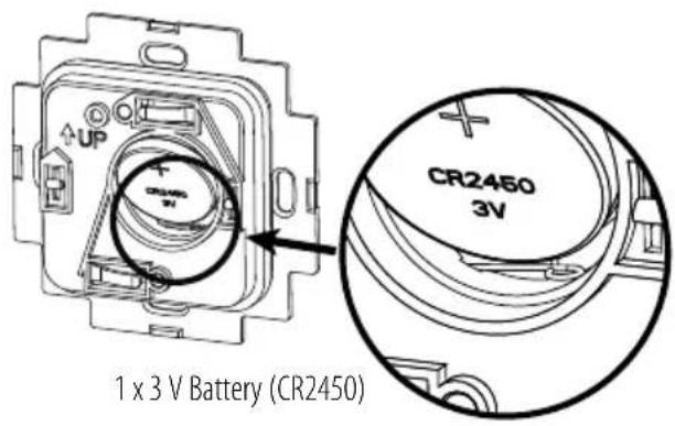
Inserting / replacing the battery
The device operates using a 3 V battery (CR2450).
natural_image
Technical line drawings of three electronic components with no visible text or symbols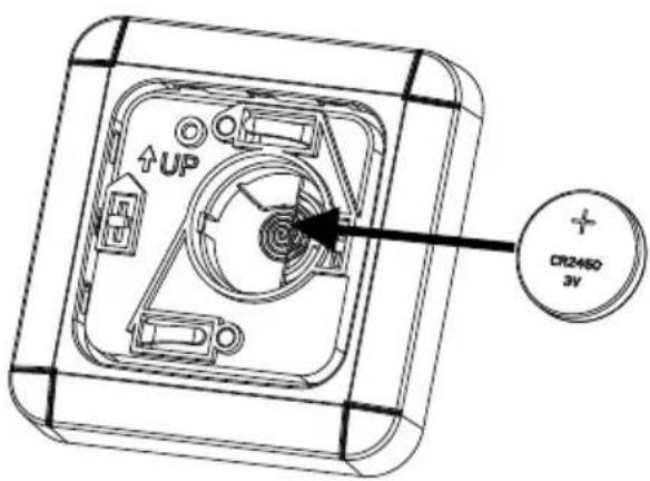

natural_image
Technical line drawings of a mechanical component assembly (no text or symbols)○ Remove the rocker switch from the cover frame.
Rotate the battery cover into the OPEN position using a coin, for example, to open the battery compartment.
○ Remove the drained battery if required.
Insert the battery into the battery compartment with correct polarity (+ pole pointing upwards).
○ Close the battery cover and secure it by rotating it into the CLOSE position.
Press the rocker switch onto the cover frame until both catches click audibly into place.
The wireless wall switch is now ready for use.
Installation
Note: Check before installation whether the product is located within the range of the Gateway.
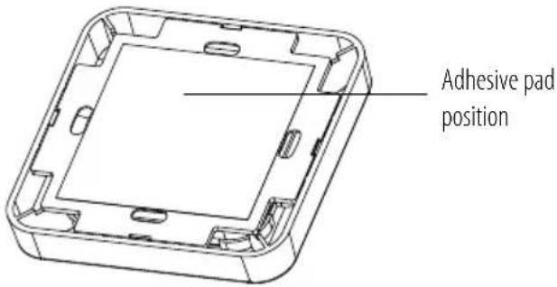
The wireless wall switch can be installed using an adhesive pad or screws on any surface.
○ An eaves, for example, is particularly suitable for outdoor installation.
○ Install the wireless wall switch with the marking (▲P) on the installation plate pointing upwards on the wall.
Installation using screws

CAUTION! DANGER OF ELECTRIC SHOCK!
Make sure that you do not damage electrical cables in the wall during installation.
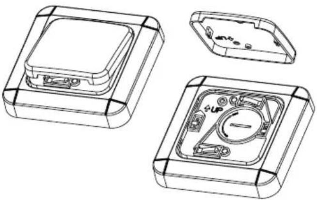
Remove the rocker switch. Press the installation plate backwards until the cover frame of the installation plate comes off the catches.
Draw the four drill holes on the wall using a pen, with the help of the installation plate.
Drill the marked holes using a suitable drill and insert the dowels.
- Screw the installation plate to the wall using the screws provided.
Note: When installing on a wood surface, use a 1.5-2 mm drill. You will not require any dowels.
Press the cover frame onto the installation plate until it audibly clicks into place.
Press the rocker switch onto the cover frame until both catches click audibly into place.
Installation using adhesive
○ Ensure that the installation area is clean, dust-free and dry.
Avoid installation locations which are under the strong influence of heat (i.e. sunlight) as the adhesive tape can come unstuck.
○ Attach the adhesive pad enclosed to the back of the device.
- Affix the wireless wall switch by gently pressing it onto the desired installation area.
Download app / PC software BrematicPRO
The Brennenstuhl Home Automation Systems BrematicPRO is controlled via the BrematicPRO app/PC software. The app can be downloaded for free from the App Store and Google Play. The PC software is available for download at www.brematic.com/gb/service. Please follow the on-screen instructions for download and installation.

Download on the App Store

GET IT ON Google Play
For more information about the app and how to use it, please visit www.brematic.com/gb/service.
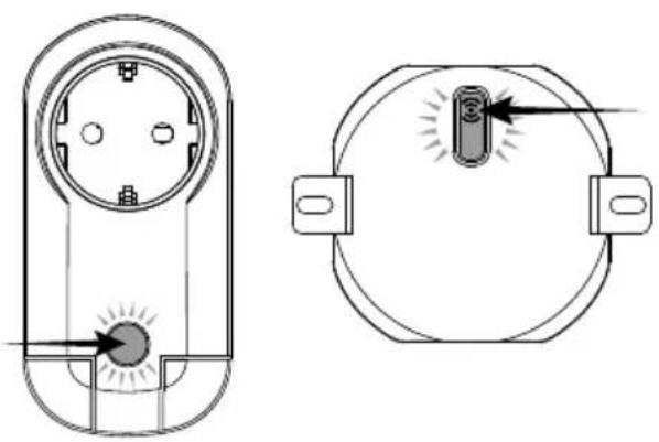
Pairing the wireless wall switch directly with BrematicPRO devices
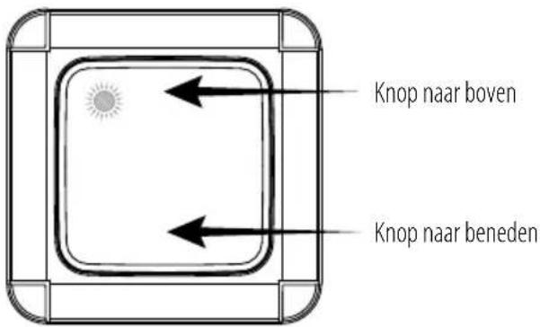
The wireless wall switch can be paired directly with the BrematicPRO wireless switch adapter or wireless flush-mounted actuators. Two separate buttons are integrated within the wireless wall switch. You can use the upper part of the rocker switch for switching a wireless switch adapter and the lower part for switching a wireless flush-mounted actuator, for example.
natural_image
Technical line drawing of a socket and bulb assembly (no text or symbols)○ Press and hold the pair button of the components to be paired for 3 seconds.
The LED will flash red.
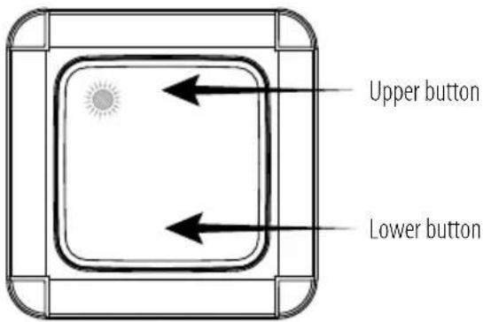
While the LED is flashing, press the upper part or lower part of the rocker switch on the wireless wall switch you would like to use.
Once both devices have been paired the device LED will briefly light up red. This completes the pairing process. The device LED will flash thrice if there has been a transmission error. Check that the device to be paired is connected.
Pairing the wireless wall switch with the BrematicPRO Gateway
When linked with the Home Automation Systems BrematicPRO via the BrematicPRO Gateway, you can use the app/BrematicPRO PC software to use additional software-based functions, e.g. functions such as controlling actions (tasks), switching devices on / off.
The app or BrematicPRO PC software is installed and open. The BrematicPRO Gateway is ready for use.
- Keep the device at least 50 cm from the gateway.
○ Open the "Settings" menu.
○ Select the room where you wish to use the device.
○ Select "Add Device".
○ Select the frequency "868 MHz".
Under "New Device", select "Switch / Socket" and click "Continue" to confirm your selection.
○ Follow the on-screen instructions.
Press the upper or lower part of the rocker switch on the wall switch. Only one rocker switch has to be programmed for the wall switch to be fully integrated within the system.
○ Enter a device name, e.g. "Wireless Wall Switch".
○ Select "Add" to assign the device to the room.
- First tap "Back" to leave the room, then "Done" to complete the pairing process.
The wireless wall switch is now connected to the Home Automation Systems BrematicPRO.
Use "Test Device" to switch the consumer on and off to ensure the wireless wall switch is working properly.
In this submenu you can also add the device to your favourites.
Note: The wireless wall switch will not appear in the registered room, but as a trigger button in Task Manager.
Cleaning the Device
○ Clean the device with a dry, lint-free cloth. For tough dirt, you may also slightly dampen the cloth.
Do not clean with solvent-based cleaners. These could damage the device surface and markings.
Never immerse the device in water or other liquids. The device may otherwise be damaged.
Action
| Problem Possible cause Action | |
| The LED is flashing. The battery is drained. | Insert a new battery. |
| Device not detected. The device is outside the range of the Gateway / the wireless components. | Reduce the distance to the Gateway / wireless components. |
Disposal
The packaging is made from environmentally-friendly materials which can be disposed of through your local recycling facilities.
Contact your local refuse disposal authority for more details of how to dispose of your worn-out product.

To help protect the environment, please dispose of the product properly when it has reached the end of its useful life, not in the household waste. Please contact your municipality for information on collection facilities and their opening hours.
Faulty or drained batteries must be recycled in accordance with Directive 2006/66/EC and its amendments. Return batteries and / or the device to the provided recycling facilities.

Improper disposal of batteries can harm the environment!
Never dispose of batteries in your household bin. They may contain toxic heavy metals and are subject to hazardous waste regulations. The chemical symbols of the heavy metals are: Cd = cadmium, Hg = mercury, Pb = lead. Therefore dispose of drained batteries through your local collection facilities.
Service
For questions related to the product, please contact us at www.brematic.com/ Tel.: 0080048720743 (toll-free)
Manufacturer
Declaration of conformity
Hugo Brennenstuhl GmbH & Co.KG, hereby declares the wireless system model APWS 868 01 IP44 to comply with directives 2014/53/EU and 2011/65/EU (RoHS II). The full text of the EU declaration of conformity is available at the following internet address: www.brennenstuhl.com/gb/service/konformitaetserklaerung/ke_1294600.pdf
This device complies with the legal, national and European requirements. All company names and product names are trademarks of the respective owners.
All rights reserved.

natural_image
Green gradient bar with no text or symbols
natural_image
Technical line drawings of three views of a device housing (no text or symbols)

natural_image
Technical line drawings of a mechanical component assembly (no text or symbols)natural_image
Simple line drawing of a socket with a pointer and base, no text or symbols present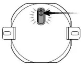
natural_image
Simple line drawing of a circular object with two side brackets and a central vertical component, no text or symbols present.natural_image
Green gradient bar with no text or symbolsNL Draadloze wandschakelaar 868.3 MHz
WAARSCHUWING! LEVENSGEVAAR!
natural_image
Technical line drawings of a mechanical housing with internal components (no text or symbols)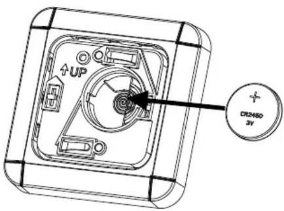

natural_image
Technical line drawings of an electronic device housing with internal components and mounting brackets (no text or symbols)Download in de App Store

natural_image
Technical line drawing of a dual-pin electrical socket with indicator lights (no text or symbols)○ Houd de „leer“-knop van de te koppelen component 3 seconden lang ingedrukt.
De led knippert rood.
natural_image
Green gradient bar with no text or symbolsnatural_image
Technical line drawings of three electronic components with mounting holes and internal circuitry (no text or symbols)

natural_image
Technical line drawings of an electronic device housing with internal components and mounting brackets (no text or symbols)natural_image
Technical line drawing of a socket with indicator lights, shown from two different angles (no text or symbols)www.brematic.com/it/service.
Tel.: 0080048720743 (gratuito)
Produttore

- Wireless wall switch4 868.3 MHz
- Safety instructions
- CAUTION! RISK OF INJURY!
- Special safety instructions for handling batteries
- WARNING! DANGER TO LIFE!
- Risk of battery leakage
- Risk of device damage
- WARNING! CHEMICAL BURNS!
- Intended use
- Information about Wireless Operation
- Duty Cycle
- Included in delivery
- Technical data
- Function
- Preparation
- Inserting / replacing the battery
- Installation
- CAUTION! DANGER OF ELECTRIC SHOCK!
- Installation using adhesive
- Download app / PC software BrematicPRO
- Pairing the wireless wall switch directly with BrematicPRO devices
- Pairing the wireless wall switch with the BrematicPRO Gateway
- Cleaning the Device
- Disposal
- Service
- Manufacturer
- Declaration of conformity
- NL Draadloze wandschakelaar 868.3 MHz
- WAARSCHUWING! LEVENSGEVAAR!
- Download in de App Store
- Produttore
Brand : BRENNENSTUHL
Model : BrematicPRO APWT868 01 IP44
Category : Smart Home