ESM4420 - Temperature Controller Emko - Free user manual and instructions
Find the device manual for free ESM4420 Emko in PDF.
| Product type | PID temperature controller |
| Brand | Emko |
| Model | ESM4420 |
| Dimensions (W x H x D) | 48 x 48 x 95 mm |
| Panel cutout | 46 x 46 mm |
| Weight | 220 g |
| Power supply | 230 V~ 50/60 Hz (other voltages available: 24 V~, 115 V~) |
| Process display (PV) | Red LED 4 digits (10.1 mm) |
| Setpoint display (SV) | Green LED 4 digits (8 mm) |
| Measurement input | Thermocouple (J, K, R, S, T) or Pt100 RTD (IEC751) |
| Accuracy | ±0.25% of full scale |
| Control output | Relay 5A@250V~ or SSR driver (24 mA, 12 V==) |
| Alarm output | Relay 5A@250V~ or SSR driver (depending on model) |
| Control functions | ON/OFF, P, PI, PD, PID, adaptive (auto-tuning) |
| Alarm types | High, low, deviation, etc. programmable |
| Protection | IP65 front panel, IP20 rear |
| Operating temperature | 0 to 50 °C |
| Humidity | 0-90% RH (non-condensing) |
| Sampling rate | 3 samples per second |
| Input filter | 1.0 second |
| Maintenance | Clean with a damp cloth or ethyl alcohol; do not use hydrocarbon solvents |
| Warranty | 2 years |
| Repairability | Have a qualified technician perform repairs; disconnect power before servicing |
Frequently Asked Questions - ESM4420 Emko
User questions about ESM4420 Emko
0 question about this device. Answer the ones you know or ask your own.
Ask a new question about this device
Download the instructions for your Temperature Controller in PDF format for free! Find your manual ESM4420 - Emko and take your electronic device back in hand. On this page are published all the documents necessary for the use of your device. ESM4420 by Emko.
USER MANUAL ESM4420 Emko
natural_image
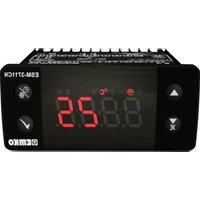
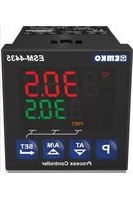
Five black industrial control unit units with digital displays and indicator lights, displayed against a gradient orange background (no readable text or symbols on devices)PID TEMPERATURE CONTROL UNITS ESM-XX20
ESM-9920, ESM-9420, ESM-7720, ESM-4920, ESM-4420 PID Temperature Control Units
- 4 digit process (PV) and 4 digit set (SV) display
- Process input (TC, RTD)
- Programmable ON/OFF, P, PI, PD and PID control forms
- Adaptation of PID Coefficients to the system with Self-Tune operation (Step Response Tuning)
- Programmable Heating or Cooling Functions for Control Output
- Selectable Alarm Functions for Alarm Output
ESM series temperature controllers are designed for measuring and controlling a process value. They can be used in many applications with their TC and RTD temperature measurement input, multi-function control outputs, selectable alarm functions.
They are mainly used in glass, plastic, petro-chemistry, textile, automotive and machine production industries. Accurate and advanced controlling is performed with selectable ON-OFF, P, PI, PD, PID and Self Tune PID functions.
Specifications
Process Input: TC, RTD
Thermocouple (TC): J, K, R, S and T (IEC584.1)(ITS90) Thermoresistance (RTD): PT-100 (IEC751)(ITS90)
Measurement Range : Please refer to Table-1 for selection of input type and scale.
Accuracy : ± 0.25% of scale for thermocouple and thermoresistance
Cold Junction Compensation: Automatically ±0.1°C/1°C
Line Compensation : Maximum 10 Ohm
Sensor Break Protection : Upscale
Sampling Cycle : 3 samples per second
Input Filter : 1.0 second.
Control Form : ON/OFF, P, PI, PD or PID (Control form can be programmed by the user.)
Output
Process Output : Relay (5A@250V\~at resistive load) or SSR
Driver Output (Maximum 24mA, Max. 12V ---)
Alarm Output: Relay(5A@250V\~ at resistive load) or SSR Driver
Output(Alarm Output - 2) (Maximum 24mA, Max. 12V = )
Supply Voltage
(It must be determined in order)
Display
Process Display :
ESM-4420 : 10.1 mm Red 4 digit LED Display
ESM-4920 : 13.2 mm Red 4 digit LED Display
ESM-7720 : 13.2 mm Red 4 digit LED Display
ESM-9420 : 10.1 mm Red 4 digit LED Display
ESM-9920 : 19 mm Red 4 digit LED Display
Set Value Display :
ESM-4420 : 8 mm Green 4 digits LED Display
ESM-4920 : 8 mm Green 4 digits LED Display
ESM-7720 : 9.1 mm Green 4 digits LED Display
ESM-9420 : 8 mm Green 4 digits LED Display
ESM 9920 : 10.8 mm G reen 4 digits LED Display
Leds : PS (Process Set Value), PO (Process Output Status Led) ,
AS1, AS2 (Alarm Set Values), AO1, AO2 (Alarm Output Status
Environmental Ratings and Physical Specifications
Operating Temperature : 0...50°C
Humidity : 0-90%RH (none condensing)
Protection Class : IP65 at front, IP20 at rear
Weight : ESM-4420 : 220 gr. , ESM-4920 : 240 gr.
ESM-7720 : 270 gr. , ESM-9420 : 230 gr.
ESM-9920 : 340 gr.
Dimension :
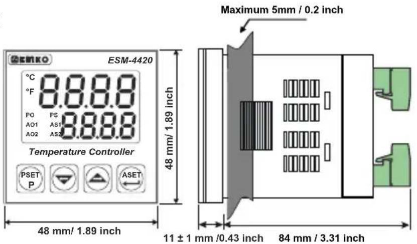
ESM-4420 : (48 x 48mm, Depth : 95mm)
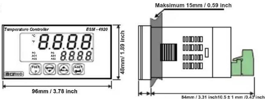
ESM-4920 : (96 x 48mm, Depth : 94.5mm)
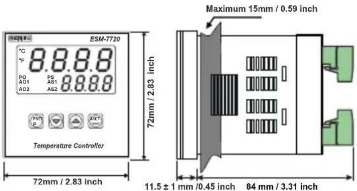
ESM-7720 : (72 x 72mm, Depth : 95.5mm)
ESM-9420 : (48 x 96mm, Depth : 94.5mm)
ESM-9920 : (96 x 96mm, Depth : 96mm)
Panel CutOut :
ESM-4420 : (46 x 46mm)
ESM-4920 : (92 x 46mm)
ESM-7720 : (69 x 69mm)
ESM-9420 : (46 x 92mm)
ESM-9920 : (92 x 92mm)
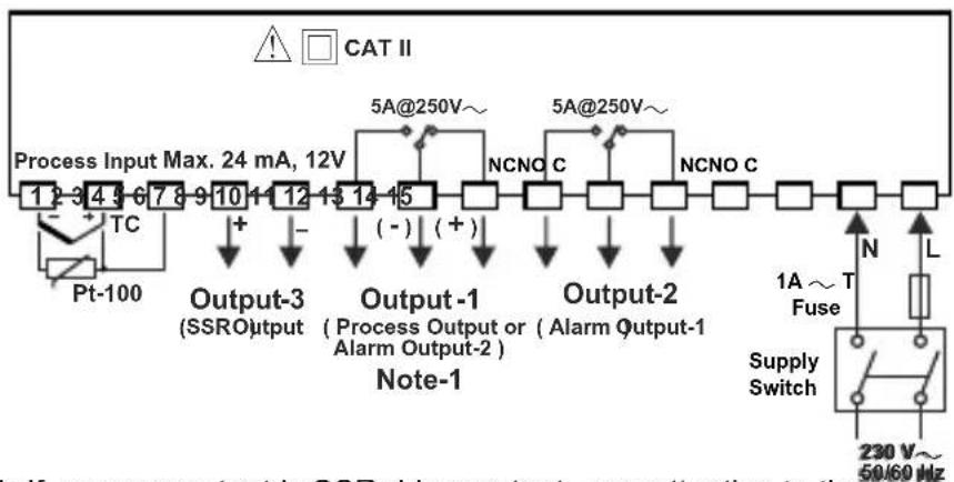
Electrical Wirings
ESM-4420
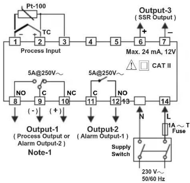
flowchart
graph TD
    A["Pt-100"] --> B["Process Input"]
    B --> C["1"]
    B --> D["2"]
    B --> E["3"]
    C --> F["4"]
    D --> G["5"]
    E --> H["6"]
    F --> I["7"]
    G --> I
    H --> I
    I --> J["Output-3 (SSR Output)"]
    J --> K["Max. 24 mA, 12V"]
    K --> L["Output-2 (Alarm Output-1)"]
    L --> M["Supply Switch"]
    M --> N["230 V~ 50/60 Hz"]
    N --> O["L 1A ~ T Fuse"]
    O --> P["Output-1 (Process Output or Alarm Output-2)"]
    P --> Q["Note-1"]
    Q --> R["8"]
    Q --> S["9"]
    R --> T["(-)"]
    S --> U["(+)"]
    T --> V["NO"]
    U --> W["NC"]
    V --> X["5A@250V~"]
    W --> Y["5A@250V~"]
    X --> Z["11"]
    Y --> AA["12"]
    Z --> AB["13"]
    AA --> AC["14"]
    AB --> AD["N"]
    AC --> AE["L"]
ESM-4920
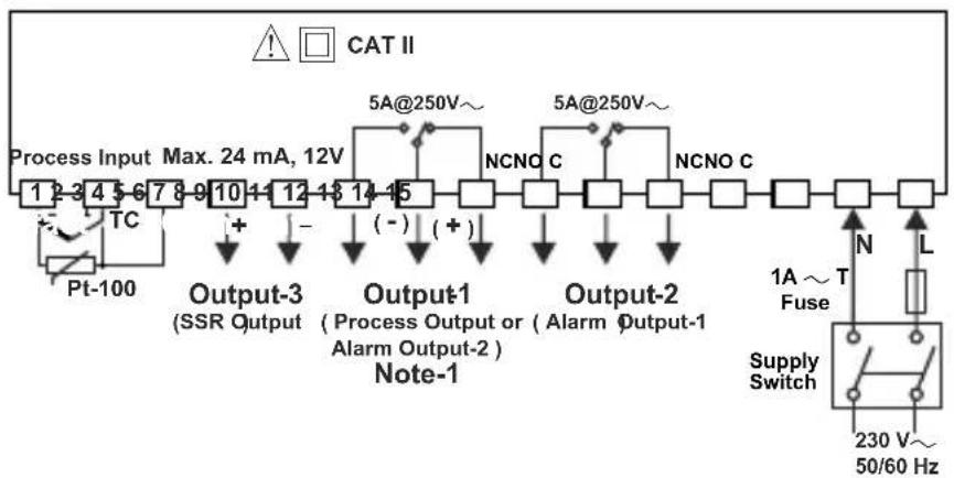
flowchart
graph TD
    A["Process Input"] --> B["Max. 24 mA, 12V"]
    B --> C["5A@250V~"]
    C --> D["Output-3 (SSR Output)"]
    D --> E["Output-1 (Process Output or Alarm Output-2) Note-1"]
    E --> F["Output-2 (Alarm Output-1)"]
    F --> G["Output-2"]
    G --> H["NCNO C"]
    H --> I["NCNO C"]
    I --> J["Output-2"]
    J --> K["Supply Switch"]
    K --> L["230 V~ 50/60 Hz"]
    M["PT-100"] --> N["TC"]
    N --> O["+"]
    O --> P["-"]
    P --> Q["(-)"]
    Q --> R["(+)"]
    R --> S["5A@250V~"]
    S --> T["5A@250V~"]
    T --> U["N"]
    U --> V["L"]
    V --> W["1A ~ T Fuse"]
    W --> X["Output-2"]
    X --> Y["Output-3"]
ESM-7720
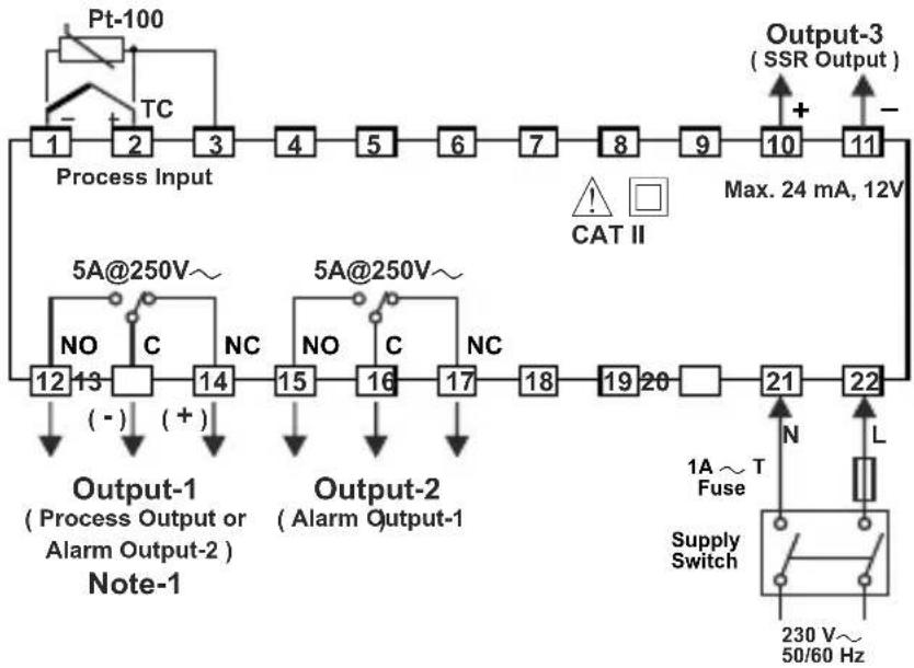
flowchart
graph TD
    A["Process Input"] --> B["1"]
    B --> C["2"]
    C --> D["3"]
    D --> E["4"]
    E --> F["5"]
    F --> G["6"]
    G --> H["7"]
    H --> I["8"]
    I --> J["9"]
    J --> K["10"]
    K --> L["11"]
    L --> M["Output-3 (SSR Output)"]
    M --> N["Max. 24 mA, 12V"]
    O["5A@250V~"] --> P["12"]
    P --> Q["13"]
    Q --> R["14"]
    R --> S["15"]
    S --> T["16"]
    T --> U["17"]
    U --> V["18"]
    V --> W["19"]
    W --> X["20"]
    X --> Y["21"]
    Y --> Z["22"]
    AA["NO"] --> AB["(-)"]
    AC["C"] --> AD["(+)"]
    AE["NC"] --> AF["(-)"]
    AG["NO"] --> AH["(-)"]
    AI["C"] --> AJ["(+)"]
    AK["NC"] --> AL["(-)"]
    AM["NO"] --> AN["(-)"]
    AO["C"] --> AP["(+)"]
    AQ["NC"] --> AR["(-)"]
    AS["NO"] --> AT["(-)"]
    AU["C"] --> AV["(+)"]
    AW["NO"] --> AX["(-)"]
    AY["5A@250V~"] --> AZ["12"]
    BA["5A@250V~"] --> BB["13"]
    BC["Output-1 (Process Output or Alarm Output-2) Note-1"] --> BD["(-)"]
    BE["Output-2 (Alarm Output-1)"] --> BF["(+)"]
    BG["1A ~ T Fuse"] --> BH["N"]
    BI["L"] --> BJ["L"]
    BK["Supply Switch"] --> BL["230 V~ 50/60 Hz"]
ESM-9420
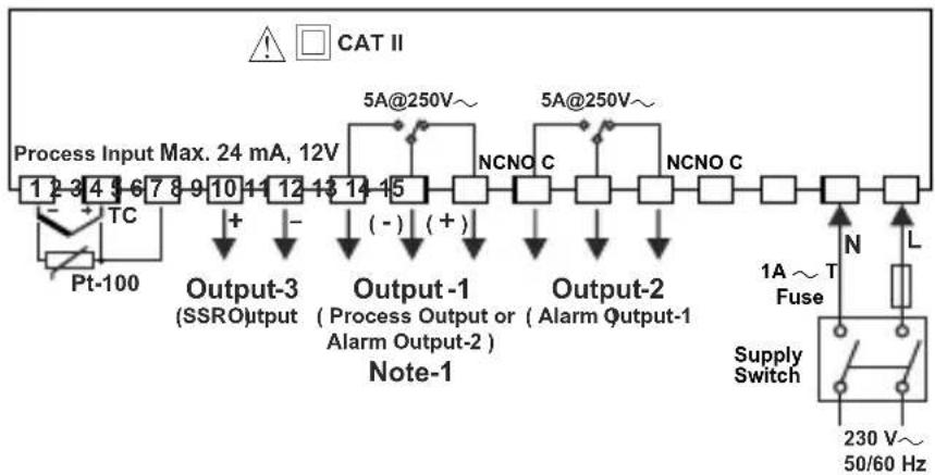
flowchart
graph TD
    A["Process Input Max. 24 mA, 12V"] --> B["Output-3 (SSRO)"]
    B --> C["Output-1 (Process Output or Alarm Output-2)"]
    C --> D["Output-2 (Alarm Output-1)"]
    D --> E["Supply Switch"]
    E --> F["1A ~ T Fuse"]
    F --> G["230 V~ 50/60 Hz"]
    H["Pt-100"] --> I["TC"]
    I --> J["+"]
    J --> K["-"]
    K --> L["(-)"]
    L --> M["NCNO C"]
    M --> N["5A@250V~"]
    N --> O["5A@250V~"]
    O --> P["NCNO C"]
    P --> Q["NCNO C"]
    Q --> R["Output-1"]
    R --> S["Note-1"]
    style A fill:#f9f,stroke:#333
    style E fill:#ccf,stroke:#333
    style F fill:#cfc,stroke:#333
    style G fill:#fcc,stroke:#333
    style H fill:#ffc,stroke:#333
    style I fill:#fcc,stroke:#333
    style J fill:#fff,stroke:#333
    style K fill:#fff,stroke:#333
    style L fill:#fff,stroke:#333
    style M fill:#fff,stroke:#333
    style N fill:#fff,stroke:#333
    style O fill:#fff,stroke:#333
    style P fill:#fff,stroke:#333
    style Q fill:#fff,stroke:#333
    style R fill:#fff,stroke:#333
    style S fill:#fff,stroke:#333
    style T fill:#fff,stroke:#333
    style U fill:#fff,stroke:#333
    style V fill:#fff,stroke:#333
    style W fill:#fff,stroke:#333
    style X fill:#fff,stroke:#333
    style Y fill:#fff,stroke:#333
    style Z fill:#fff,stroke:#333
ESM-9920
flowchart
graph TD
    A["Process Input Max. 24 mA, 12V"] --> B["TC"]
    B --> C["Pt-100"]
    C --> D["Output-3 (SSRO)"]
    D --> E["+"]
    E --> F["Output-1 (Process Output or Alarm Output-2)"]
    F --> G["(-)"]
    G --> H["Output-2"]
    H --> I["NCNO C"]
    I --> J["5A@250V~"]
    J --> K["5A@250V~"]
    K --> L["NCNO C"]
    L --> M["Output-2"]
    M --> N["1A ~ T Fuse"]
    N --> O["Supply Switch"]
    O --> P["230 V~ 50/60 Hz"]
    style A fill:#f9f,stroke:#333
    style P fill:#ccf,stroke:#333
Note-1: If process output is SSR driver output, pay attention to the (+) and (-) pins while doing the connection of the device
Dimension
ESM-4420
text_image
ESM-4420 Temperature Controller PSET P ASET 8.8.8.8 8.8.8.8 PO PS AO1 AS1 AO2 AS2 48 mm/ 1.89 inch Maximum 5mm / 0.2 inch 11 ± 1 mm /0.43 inch 84 mm / 3.31 inch 48 mm/ 1.89 inchESM-4920
text_image
Temperature Controller ESM - 4920 °C 8.8.8.8 °F PO P8 A51 A01 A52 A02 PSET A3ET P A3ET 48mm/ 1.89 inch 96mm / 3.78 inch Maksimum 15mm / 0.59 inch 84mm / 3.31 inch10.5 ± 1 mm /0.43 inchESM-7720
text_image
ESM-7720 °C 8.8.8.8 °F PO PS AO1 AS1 8.8.8.8 AO2 AS2 PSCT ASCT Temperature Controller 72mm / 2.83 inch 72mm / 2.83 inch Maximum 15mm / 0.59 inch 11.5 ± 1 mm /0.45 inch 84 mm / 3.31 inch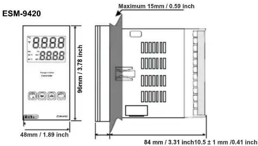
text_image
ESM-9420 Temperature Controller 96mm / 3.78 inch 48mm / 1.89 inch Maximum 15mm / 0.59 inch 84 mm / 3.31 inch10.5 ± 1 mm /0.41 inch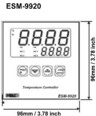
text_image
ESM-9920 8.8.8.8 °C °F PRO PSE AO 1 AS 1 8.6.8.8 AO 2 AS 2 PSET P ASSET ASSET Temperature Controller ESM-9920 96mm / 3.78 inch 96mm / 3.78 inch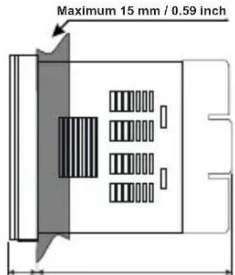
text_image
Maximum 15 mm / 0.59 inch84 mm / 3.31 inch12 ± 1 mm /0.47 inch
Panel Mounting
text_image
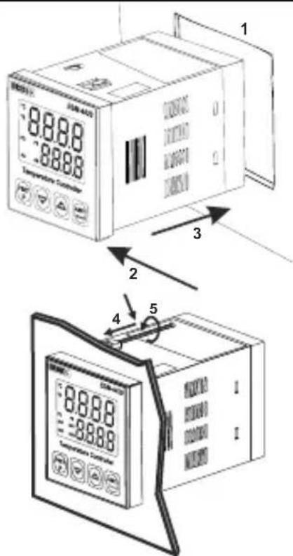
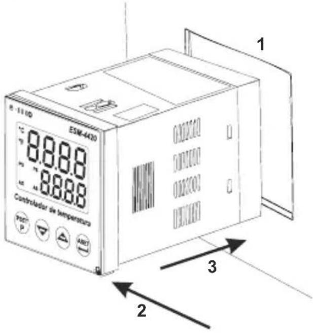
8.8.88 8.8.88 Temperature Control 1 2 3 4 51-Before mounting the device in your panel, make sure that the cutout is of the right size.
2-Check front panel gasket position
3-Insert the device through the cutout. If the mounting clamps are on
the unit, put out them before inserting the unit to the panel.
4-Insert the unit in the panel cut-out from the front side.
5- Insert the mounting clamps to the holes that located top and bottom sides of device and screw up the fixing screws until the unit completely immobile within the panel.
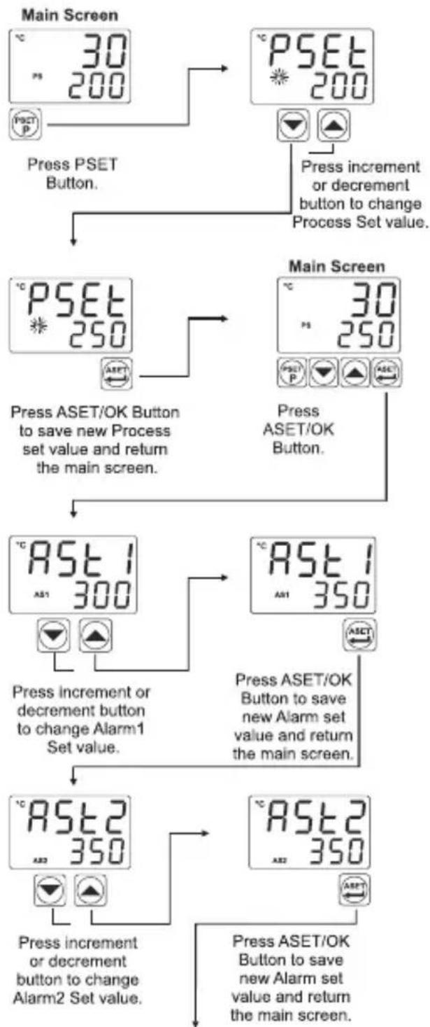
Access and Change Set Values
flowchart
graph TD
    A["Main Screen"] --> B["Press PSET Button."]
    B --> C["Press increment or decrement button to change Process Set value."]
    C --> D["Main Screen"]
    D --> E["Press ASET/OK Button to save new Process set value and return the main screen."]
    E --> F["Press increment or decrement button to change Alarm1 Set value."]
    F --> G["Press ASET/OK Button to save new Alarm set value and return the main screen."]
    G --> H["Press increment or decrement button to change Alarm2 Set value."]
    H --> I["Press ASET/OK Button to save new Alarm set value and return the main screen."]
Note: User can exit from Set Value section without saving the values by pressing 📄 button.
If no operation for 120 seconds, device automatically exits from Set Value section.
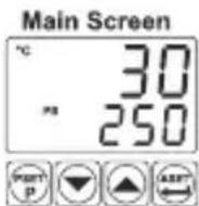
Easy Access Diagram For Program Parameters
flowchart
graph TD
    A["30 200"] --> B["PSET 200"]
    B --> C["ProG"]
    C --> D["PrPS 0"]
    D --> E["PrPS 100"]
    E --> F["To enter Program menu press & button for 5 seconds."]
    F --> G["After 5 sec."]
    G --> H["Press ASET/OK Button to access Password Screen."]
    H --> I["Enter Password with increment or decrement buttons."]
    I --> J["Approve password with ASET/OK Button."]
    J --> K["ProS"]
    K --> L["Cont"]
    L --> M["Cout rLy"]
    M --> N["PrtS HEAT"]
    N --> O["PrtS Cool"]
    O --> P["RtS 1 PH,R"]
    P --> Q["RLr"]
    Q --> R["Prot"]
    R --> S["PrPS 100"]
    S --> T["PrPS Main Screen"]
    T --> U["PLoL -200"]
    U --> V["PuPL 900"]
    V --> W["SU-L -200"]
    W --> X["SU-u 900"]
    X --> Y["PUoF 0"]
    Y --> Z["SSCT 1"]
    Z --> AA["SSCT 100"]
    AA --> AB["tCon 10"]
    AB --> AC["AtET 100"]
    AC --> AD["tdEr 250"]
    AD --> AE["AtET 100"]
    AE --> AF["Ron 1 0"]
    AF --> AG["RuP 1 500"]
    AG --> AH["RuF 1 0"]
    AH --> AI["AtET 100"]
    AI --> AJ["AtET 100"]
    AJ --> AK["AtET 100"]
    AK --> AL["AtET 100"]
    AL --> AM["AtET 100"]
    AM --> AN["AtET 100"]
Note: If user does not do anything for 120 seconds while device is on programming section, device turns to operation screen.
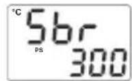
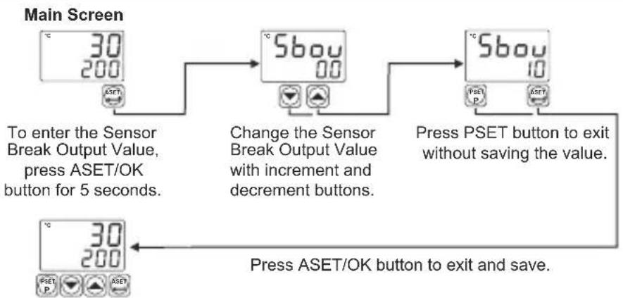
Easy Access Diagram For Sensor Break Output Value
flowchart
graph TD
    A["Main Screen"] --> B["To enter the Sensor Break Output Value, press ASET/OK button for 5 seconds."]
    B --> C["Change the Sensor Break Output Value with increment and decrement buttons."]
    C --> D["Press PSET button to exit without saving the value."]
    D --> E["Press ASET/OK button to exit and save."]
Note: If user does not do anything for 120 seconds while device is on this section, device turns to operation screen.
Note-2: Sensor Break Output Value can be adjusted on programming section too.
Tune Operation
Starting the Tune operation
1-Enter to the programming section
2- Select YES, Text parameter in Cont menu. Press ASET/OK button for saving the parameter and turn to the main operation screen.
3- Observe that "Lune" blinks in set display.
Note- For starting the Tune operation,
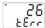
Heating Tune Operation: Process value must be lower than process set value at least 5% of full scale tErr
Cooling Tune Operation :Process value must be greater than process set value at least 5% of the full scale. If this condition is not okay, Blinks on the screen for 10 seconds.
Canceling Self Tune operation :
1- If sensor breaks ;
2- If Self Tune operation can not be completed in 8 hours ;
3- While heating Self Tune is running, if process value becomes greater than Process Set value
4- While cooling Self Tune is running, if process value becomes less than Process Set value;
5- While Self Tune operation is running, if user changes the process set value;
Then Self Tune operation is canceled, device continues to run with former PID parameters without changing PID parameters.
Pro5 : Process Menu Parameters
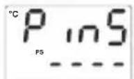
text_image
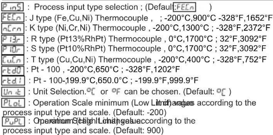
P_inS : Process input type selection ; (Default:FEEn) FEEn : J type (Fe,Cu,Ni) Thermocouple , ; -200°C,900°C -328°F,1652°F nCrn : K type (Ni,Cr,Ni) Thermocouple , -200°C,1300°C ; -328°F,2372°F P13r : R type (Pt13%RhPt) Thermocouple , 0°C,1700°C ; 32°F,3092°F P10r : S type (Pt10%RhPt) Thermocouple , 0°C,1700°C ; 32°F,3092°F CuCn : T type (Cu,Cu,Ni) Thermocouple , -200°C,400°C ; -328°F,752°F rtdU : Pt - 100 , -200°C,650°C ; -328°F,1202°F rtdI : Pt - 100,-199.9°C,650.0°C ; -199.9°F,999.9°F Unit : Unit Selection.°C or °F can be chosen. (Default: °C ) PLoL : Operation Scale minimum (Low Limit) averages according to the process input type and scale. (Default: -200) PuPL : Operation Scale Minimum values according to the process input type and scale. (Default: 900)SU-L : Process Set value Low Limit. Minimum set value is defined with this parameter. It changes according to the process input type and scale. (Default: -200)
SU-u : Process Set value High Limit. Maximum set value is defined with this parameter. It changes according to the process input type and scale. (Default: 900)
P_UoF : Display offset for process value. It can be adjusted from -10% of scale to 10% of scale. It is added to the process display value. (Default: 0)
Note: If process input type selection( P inS ) is changed, PLoL , PuPL

parameters may need to be updated according to the input type selection.
Cont : Control Menu Parameters
This parameter determines, which output will be Process control output. If rLY is chosen, process output is relay output, if SSr is chosen, process output is SSR output. (Default: Ssr)
Pr-ES : Process Type Selection. It can be HERE or Cool .(Default: HERE)
CntS : Process Control Type Selection. It can be onoF or P_id .(Default: onoF )
tunE : If tune parameter is set to YES, device start to calculate PID parameters automatically. This parameter is shown if 5 = _id . (Default: no)
Prbn : Proportional band. It can be adjusted from %1 to %100. If Cn≤S = P_id, then this parameter can be observed. (Default: 10.0)
t : Integral Time. 0 can 360 asjaced. from = , the m5 P rd this parameter can be observed. (Default: 100)
tdEr : Derivative Time. It can be adjusted from = , then Cnt5 P_id this parameter can be observed. (Default: 25.0)
Con : Output Control Period. If can 150 adjusted from If then this parameter can be observed. (Default: 10)
HYS: Hysteresis value. It of the Scal adjusted from %0 ile %50 ( - If CntS=oneF, then this parameter can be observed (Default: 3)
5bou : Sensor Break Output Value. %0 to %100. It can be adjusted from (Default: 0.0)
SSET : Soft Start Set value. Device operates in Soft Start mode, until the temperature reaches Soft Start set value. (Default: no)
SSCo : Soft Start Control Output. This parameter determines soft start mode control output percentage. (Default: 10.0)
SSCt : Soft Start Control time. This parameter determines soft start mode control time (Default:1)
ALAB : Alarm Menu Parameters
RHS1 : Alarm Hysteresis value.It.can be adjusted from %0 ile %50 of the Scale( R_uPL - R_LoL ) (Default: 0)
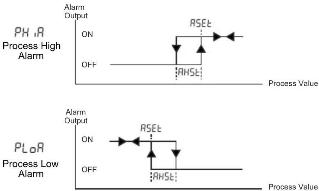
RES1 : Alarm Type selection. (Default: PH,R)
ALo1 : Alarm Set Low Limit parameter. It can be adjusted from Operation Scale minimum to Alarm Set High Limit. (Default: 0)
_uP! : Alarm Set High Limit parameter. It can be adjusted from Alarm Set Low Limit to Operation Scale maximum. (Default: 500)
: Alarm on Delay Time. It can be adjusted from 0 to 9999 seconds. (Default: 0)
RoFi : Alarm off Delay Time. It can be adjusted from 0 to 9998 seconds. If it is higher than 9998, LECH, is seen on the screen and Alarm Latching Output is selected. (Default: 0)
RH52: Alarm Hysteresis value. It can be adjusted from %0 ile %50 of the Scale (RuPL - RLoL). (Default: 0)
AtS2 : Alarm Type selection. (Default: PH,R)
ALo2 : Alarm Set Low Limit parameter. It can be adjusted from Operation Scale minimum to Alarm Set High Limit. (Default: 0)
R_uP2 : Alarm Set High Limit parameter. It can be adjusted from Alarm Set Low Limit to Operation Scale maximum. (Default: 500)
_one2 : Alarm on Delay Time. It can be adjusted from 0 to 9999 seconds. (Default: 0)
RoF2 : Alarm off Delay Time. It can be adjusted from 0 to 9998 seconds. If it is higher than 9998, LCH is seen on the screen and Alarm Latching Output is selected. (Default: 0)
NOTE: Alarm-2 parameters(AHS2, AtS2, Alo2, AuP2, Aon2, AoF2) are active, if Cout parameter is set as SSR.
Prot : Protection Menu Parameter
PrPS : Password for accessing to the programming section. It can be adjusted from 0 to 9999. If PrPS is 0, password screen is not observed. If PrPS is different from 0 and user enters to the menu pages without entering the password, all the menus can be observed except protection menu Prot. But device does not allow to do any changes in parameters. (Default value is 0)
Alarm Types
line
| Phase | Process Value | Event Type | Label | |-------|---------------|------------|-------| | PH.1A | High | ON | | | PH.1A | High | OFF | | | PH.1A | High | AHSE | | | PLoR | Low | ON | | | PLoR | Low | OFF | | | PLoR | Low | AHSE | |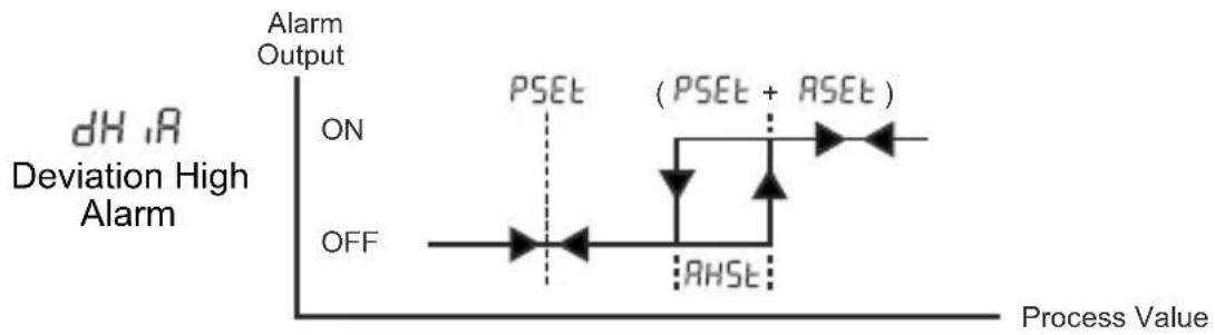
line
| Process Value | Alarm Output | | ------------- | ------------ | | ON | OFF | | PSEt | ON | | AHST | ON | | (PSEt + AHST)| Peak |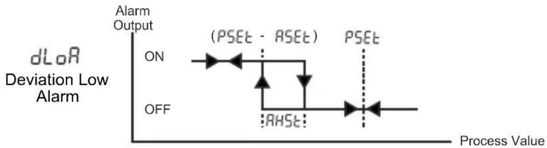
line
| Process Value | Alarm Output | | ------------- | ------------ | | ON | ON | | AHST | AHST |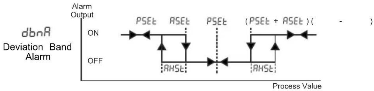
other
| Phase | Description | |-------------|--------------------------------| | ON | PSET | | ON | ASET | | ON | PSET | | ON | (PSET + ASET) ( - ) | | OFF | RHST | | OFF | RHST |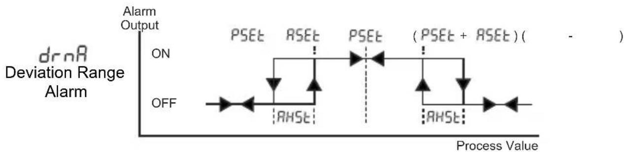
line
| Process Value | Alarm Output | | ------------- | ------------ | | ON | PSET | | ON | RSET | | ON | PSET + RHST | | ON | (PSET + RSET)| | OFF | | | OH | |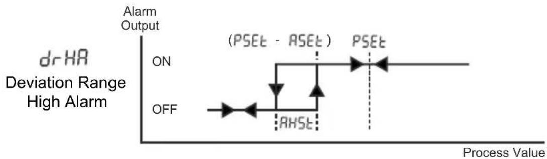
line
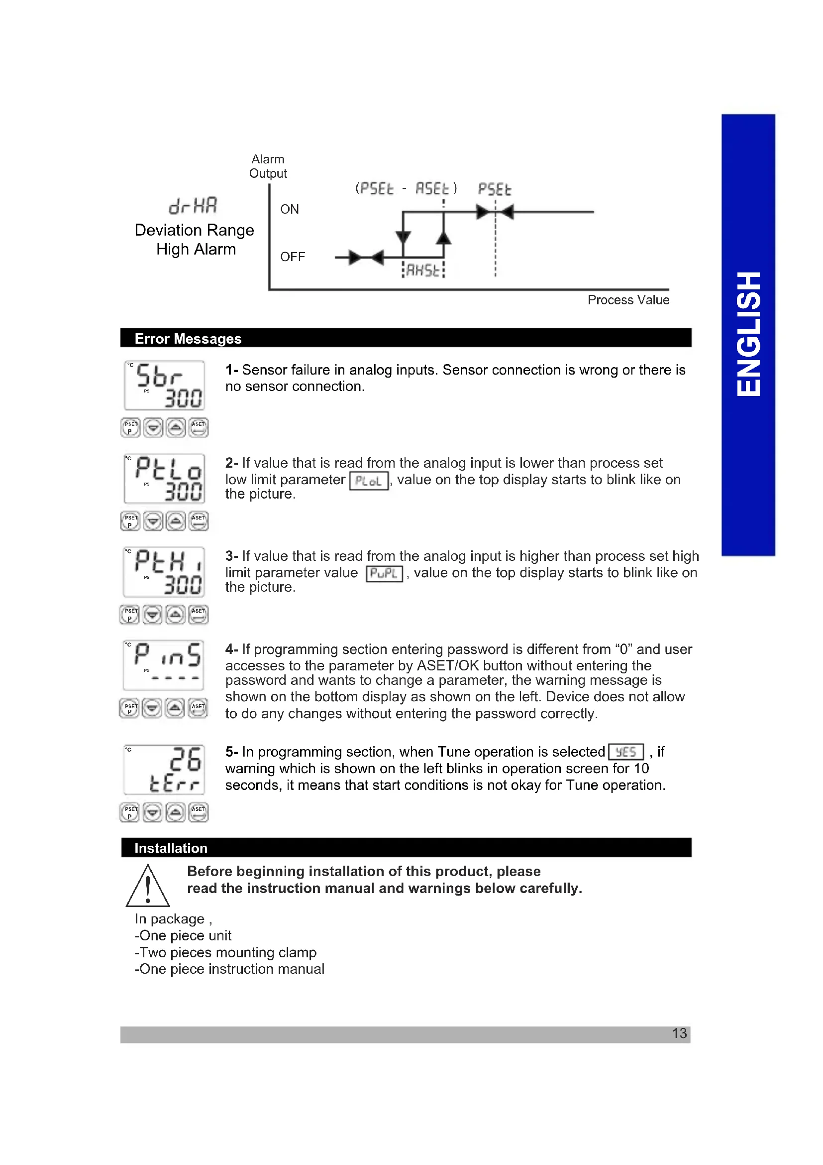
| Process Value | Alarm Output | | ------------- | ------------ | | ON | ON | | (PSEt - ASEt) | (PSEt - ASEt) | | PSEt | PSEt | | RHSE | RHSE |Error Messages


1- Sensor failure in analog inputs. Sensor connection is wrong or there is no sensor connection.
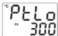
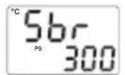
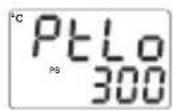
2- If value that is read from the analog input is lower than process set low limit parameter P_LoL , value on the top display starts to blink like on the picture.
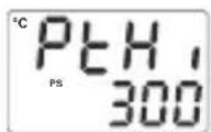
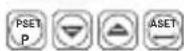
3- If value that is read from the analog input is higher than process set high limit parameter value P_UPL , value on the top display starts to blink like on the picture.
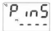
4- If programming section entering password is different from "0" and user accesses to the parameter by ASET/OK button without entering the password and wants to change a parameter, the warning message is shown on the bottom display as shown on the left. Device does not allow to do any changes without entering the password correctly.
5- In programming section, when Tune operation is selected YES, if warning which is shown on the left blinks in operation screen for 10 seconds, it means that start conditions is not okay for Tune operation.
Installation

Before beginning installation of this product, please read the instruction manual and warnings below carefully.
In package,
-One piece unit
-Two pieces mounting clamp
-One piece instruction manual
A visual inspection of this product for possible damage occurred during shipment is recommended before installation. It is your responsibility to ensure that qualified mechanical and electrical technicians install this product.
If there is danger of serious accident resulting from a failure or defect in this unit, power off the system and the electrical connection of the device from the system.
The unit is normally supplied without a power switch or a fuse. Use power switch and fuse as required.
Be sure to use the rated power supply voltage to protect the unit against damage and to prevent failure.
Keep the power off until all of the wiring is completed so that electric shock and trouble with the unit can be prevented.
Never attempt to disassemble, modify or repair this unit. Tampering with the unit may results in malfunction, electric shock or fire.
Do not use the unit in combustible or explosive gaseous atmospheres. During the equipment is putted in hole on the metal panel while mechanical installation some metal burrs can cause injury on hands, you must be careful.
Montage of the product on a system must be done with it's mounting clamp. Do not do the montage of the device with inappropriate mounting clamp. Be sure that device will not fall while doing the montage.
It is your responsibility if this equipment is used in a manner not specified in this instruction manual.
Warranty
EMKO Elektronik warrants that the equipment delivered is free from defects in material and workmanship. This warranty is provided for a period of two years. The warranty period starts from the delivery date.
This warranty is in force if duty and responsibilities which are determined in warranty document and instruction manual performs by the customer completely.
Maintenance
Repairs should only be performed by trained and specialized personnel. Cut power to the device before accessing internal parts. Do not clean the case with hydrocarbon-based solvents (Petrol, Trichlorethylene etc.). Use of these solvents can reduce the mechanical reliability of the device. Use a cloth dampened in ethyl alcohol or water to clean the external plastic case.
Other Information:
Manufacturer Information:
Emko Elektronik Sanayi ve Ticaret A.Ş.
Repair and Maintenance Service Information:
Emko Elektronik Sanayi ve Ticaret A.Ş.
| A | BC | D | E | / | FG | HI | / | U | V | W | Z |
| 0 | / | 01 | 02 | / | 0 | 0 | 0 | 0 |
| A | Supply Voltage |
| 2 | 24V ~ 50/60Hz or 24V= ( ± %15 ) |
| 3 | 24V ~ ( ± %15 ) 50/60Hz |
| 4 | 115V ~ ( ± %15 ) 50/60Hz |
| 5 | 230V ~ ( ± %15 ) 50/60Hz |
| 9 | Customer |
| BC | Input Type | Scale |
| 20 | Configurable (Table-1) | (Table-1) |
| D | Serial Communication | |
| 0 | None | |
| E | Output-1(Process or Alarm) | |
| 1 | Relay Output (5A@250V~ Resistive Load) | |
| 2 | SSR Driver Output (Max. 24mA, Max.12V = = = ) | |
| FG | Output-2(Alarm) | |
| 01 | Relay Output (5A@250V~ Resistive Load) | |
| HI | Output-3(Process) | |
| 02 | SSR Driver Output (Max. 24mA, Max.12V = = = ) | |
Table-1
| BC | Input Type(TC) | Scale(°C) | Scale(°F) |
| 23 | J ,Fe CuNi IEC584.1(ITS90) | -200°C,1300°C | -328°F,2372°F |
| 25 | K ,NiCr Ni IEC584.1(ITS90) | 0°C,1700°C | 32°F,3092°F |
| 27 | R ,Pt13%Rh Pt IEC584.1(ITS90) | 0°C,1700°C | 32°F,3092°F |
| 28 | S ,Pt10%Rh Pt IEC584.1(ITS90) | 0°C,1700°C | 32°F,3092°F |
| 29 | T ,Cu CuNi IEC584.1(ITS90) | -200°C,400°C | -328°F,752°F |
| BC | Input Type(RTD) | Scale(°C) | Scale(°F) |
| 39 | PT 100 , IEC751(ITS90) | -200°C,650°C | -328°F,1202°F |
| 40 | PT 100 , IEC751(ITS90) | -199.9°C,650.0°C | -199.9°F,999.9°F |


natural_image
Five black industrial control unit units with digital displays and buttons, displayed against a gradient orange background (no readable text or symbols on devices)PID TEMPERATURREGLER ESM-XX20
ESM-9920, ESM-9420, ESM-7720, ESM-4920, ESM-4420 PID Temperaturregler
line
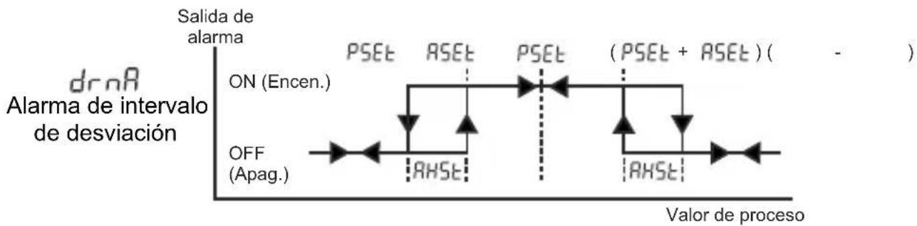
| Process | Signal | |---------|--------| | ON | ON | | Off | OFF |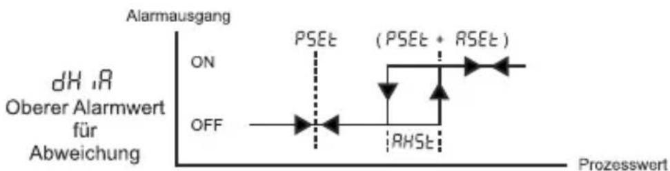
line
| Prozesswert | dH, rR Oberer Alarmwert für Abweichung | | ----------- | -------------------------------------- | | Low | ON | | High | Off |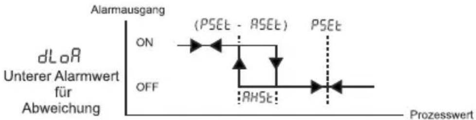
line
| Phase | Value | |-------|-------| | ON | ON | | RHSt | RHSt |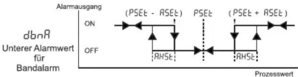
other
| State | Label | Description | |-------|---------------|--------------------------| | ON | (PSEt - ASET) | (PSEt - ASET) | | OFF | RHSE | (PSEt + ASET) |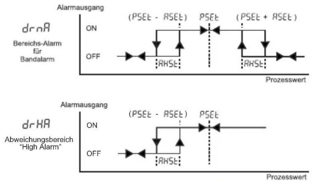
| A | BC | D | E | / | FG | HI | / | U | V | W | Z |
| 0 | 1 | / | 01 | 02 | / | 0 | 0 | 0 | 0 |
| A | Versorgungsspannung |
| 2 | 24V ~ 50/60Hz or 24V==( ± %15 ) |
| 3 | 24V ~ ( ± %15 ) 50/60Hz |
| 4 | 115V ~ ( ± %15 ) 50/60Hz |
| 5 | 230V ~ ( ± %15 ) 50/60Hz |
| 9 | Kundenspezifisch |
natural_image
Five black industrial control unit units with digital displays and indicator lights, displayed against a plain orange background (no readable text or symbols on devices)RÉGULATEURS DE TEMPÉRATURE PID ESM-XX20
ESM-4420, ESM-7720, ESM-9920
TENSION D'ALIMENTATION
230V ∼ (±15%) 50/60 Hz - 3VA
115V ∼ (±15%) 50/60 Hz - 3VA
24V ∼ ( ±15% ) 50/60 Hz - 3VA
natural_image
Diagram of a room interior with ventilation grilles and a green wall-mounted unit (no text or symbols)12 ± 1 mm /0,47 pouce 84 mm / 3,31 pouce
MONTAGE SUR PANNEAU

text_image
E3M-4420 °C 8.8.8 T F P0 P1 8.8.8 A0 A1 Régulétaur de température 1 3 2natural_image
Five black industrial control unit blocks with digital displays and buttons, displayed against a plain orange background (no readable text or symbols on main devices)natural_image
Diagram of a room layout with door, vent, and window (no text or labels)12 ± 1 mm /0,47 pulgadas
84 mm / 3,31 pulgadas
MONTAJE DEL PANEL
text_image
E3M-4420 8.8.8.8 8.8.8.8 7.8.8.8 6.8.8.8 6.8.8.8 6.8.8.8 6.8.8.8 6.8.8.8 6.8.8.8 6.8.8.8 6.8.8.8 6.8.8.8 6.8.8.8 6.8.8.8 6.8.8.8 6.8.100 6.8.100 6.8.100 6.8.100 6.8.100 6.8.100 6.8.100 6.8.100 6.8.100 6.8.100 6.8.100 6.8.100 6.8.100 6.5 10 2 3line
| Event | Value | |-------|-------| | ON (Encen.) | 0 | | OFF (Apag.) | 0 | | PSEt | 0 | | AHST | 0 | | (PSEt + RSEt) | 0 |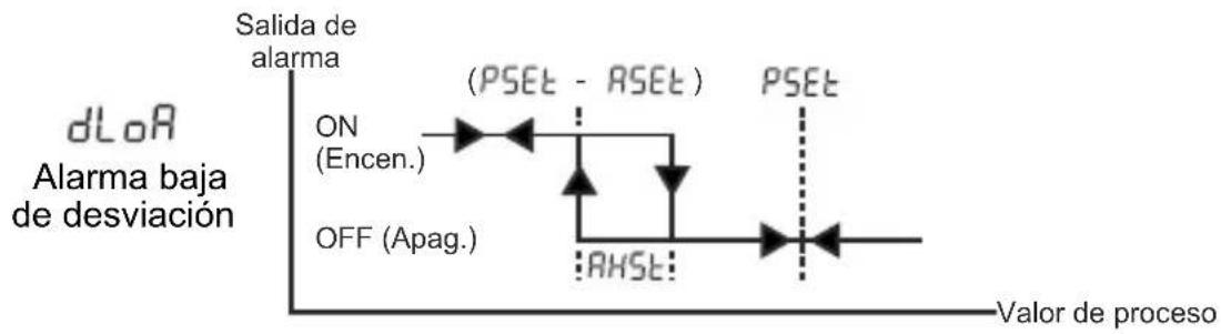
line
| Event | Value | |-------|-------| | ON (Encen.) | (PSEt - RSEt) | | OFF (Apag.) | AHST | | Salida de alarma | (PSEt - RSEt) | | Valor de proceso | PSEt |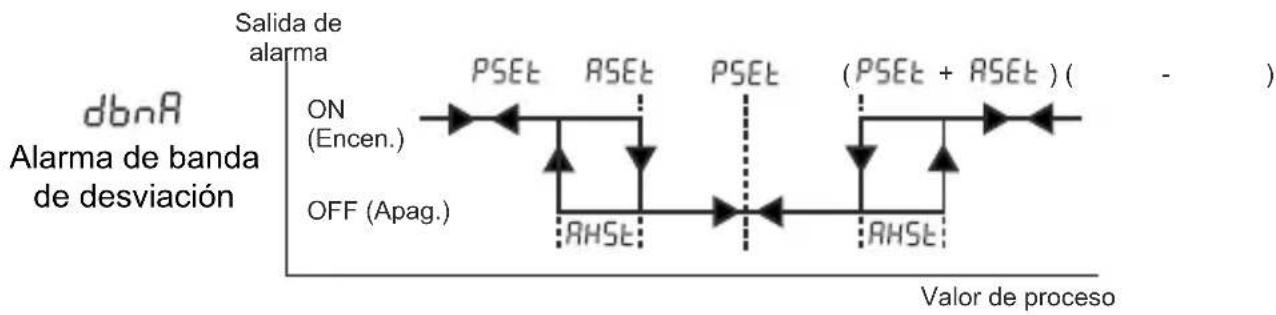
flowchart
graph LR
    A["Salida de alarma"] --> B["ON (Encen.)"]
    B --> C["PSEt"]
    C --> D["RSEt"]
    D --> E["PSEt"]
    E --> F["(PSEt + RSEt) ( - )"]
    F --> G["RHSE"]
    G --> H["OFF (Apag.)"]
    H --> I["Off (Apag.)"]
    I --> J["Off (Apag.)"]
other
| State | Description | |-------------|--------------------------| | ON (Encen.) | ON (Encen.) | | PSET | PSET | | RSET | RSET | | PSET | PSET | | (PSET + RSET) | (PSET + RSET) | | OFF (Apag.) | OFF |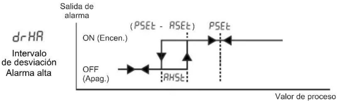
line
| Event | Value | |-------|-------| | ON (Encen.) | (PSEt - RSEt) | | RHST | (PSEt - RSEt) | | PSEt | (PSEt - RSEt) | | Off (Apag.) | (PSEt - RSEt) |Mensajes de error