
21076 - Compressor EAL - Free user manual and instructions
Find the device manual for free 21076 EAL in PDF.
| Product type | Dual power compressor |
| Brand | EAL |
| Model | 21076 |
| Power supply | 230 V ~ 50 Hz AC or 12 V DC (vehicle battery) |
| Maximum pressure | 8.3 bar / 120 psi |
| Flow rate | 25 L/min |
| Dimensions (L x W x H) | approx. 14.5 x 23 x 24 cm |
| Weight without accessories | approx. 2.14 kg |
| Pneumatic hose length | 65 cm |
| Included items | Compressor, 12 V cable, 230 V cable, 2 fuses (15 A 250 V and 2 A 250 V), adapters ∅ 5 mm, ∅ 8 mm and for balloons, user manual |
| Use | Inflation of tires (car, motorcycle, bicycle), balloons, mattresses, inflatable boats |
| Protection | IP20 (indoor use, dry environment) |
| Protection class | II (double insulation) |
| Storage temperature | -30°C to +30°C |
| Continuous operation time | 5 minutes max, then cooling 20 minutes minimum |
| Maintenance and cleaning | Clean with a soft dry cloth; do not use solvents; do not immerse |
| Fuses | 12 V fuse: fast 15 A 250 V (in the plug); 230 V fuse: 2 A 250 V (in the compartment) |
| Included accessories | Adapters for valves (5 mm, 8 mm) and balloons |
| Safety | Do not use on people or animals; do not exceed recommended pressure; do not block ventilation openings |
| General information | Suitable for domestic use, not industrial; supplied with multilingual manual (FR, DE, EN, IT, NL) |
Frequently Asked Questions - 21076 EAL
User questions about 21076 EAL
0 question about this device. Answer the ones you know or ask your own.
Ask a new question about this device
Download the instructions for your Compressor in PDF format for free! Find your manual 21076 - EAL and take your electronic device back in hand. On this page are published all the documents necessary for the use of your device. 21076 by EAL.
USER MANUAL 21076 EAL

GB DUAL POWER COMPRESSOR with 12V and 230V connections
Item number 21076
Contents
- Proper use of the product 6
- Scope of delivery 6
- Specifications 6
- Safety precautions 7
- Explanations of symbols 7
- Operating instructions 8 6.1 Overview 8 6.2 Operating the compressor 8 6.2.1 Filling a tyre using the car valve (Schrader valve) 8 6.2.2 Using the adapter 9 6.2.3 Conversion table psi / bar 9 6.3 Replacing the fuses 9 6.3.1 Replacing the fuse for the 12 V system 9 6.3.2 Replacing the fuse for the 230 V system 9 6.4 Troubleshooting 10
- Maintenance and care 10 7.1 Maintenance 10 7.2 Care 10
- Notes regarding environmental protection 10
- Contact information 10
WARNING

Read the operating instructions carefully prior to initial use and observe all of the safety notes! Not observing such may lead to personal injuries, damages to the device or to your property! Store the original packaging, the receipt and these instructions so that they may be consulted at a later date! When passing on the product, please include these operating instructions as well. Please check the contents of package for integrity and completeness prior to use!
1. Proper use of the product
The dual power compressor is designed for universal use e.g. for pumping car, motorbike and bicycle tyres, sport balls, inflatable toys, air beds and inflatable boats.
It may be connected to the 12 V on-board network of a vehicle or the 230 V household network. The manometer can be used during the filling process to monitor the pressure.
This device is not designed to be used by children or persons with limited mental abilities or without experience and/or lack of required specialist knowledge. Keep children away from the device.
The device is not designated for commercial use.
Use according to the intended purpose also includes the observance of all information in these operating instructions, particularly the observance of the safety notes. Any other utilisation is considered to be contrary to the intended purpose and may lead to material damages or personal injuries. EAL GmbH assumes no liability for damages resulting from improper use.
2. Scope of delivery
- 1x Dual Power Compressor
- 1x Adapter ø 5 mm
- 1x Operating instructions
- 1x Fuse, fast 15 A 250 V, 6 x 30
- 1x Adapter ø 8 mm
- 1x Fuse 2 A 250 V, 5 x 20
- 1x Ball adapter
3. Specifications
| Input voltage: | 230 V 50 Hz AC | Weight (without accessories): | Approximately 2.140 kg |
| 12 V DC | Length of air hose: | 0.65 cm | |
| Maximum pressure: | 8.3 bar / 120 psi | Length of 12 V – cable: | 3.50 m |
| Volume flow: | 25 l/min | Length of 230 V – cable: | 1 m |
| Dimensions (L x W x H): | Approximately 14.5 x 23 x 24 [cm] |
4. Safety precautions

- The warning symbol indicates all instructions which are important for safety. Always follow these, otherwise you could injure yourself or damage the device. • Children may not play with the device.
- Cleaning and user maintenance may not be carried out by children without supervision.
- Do not treat packaging material carelessly. This may become a dangerous plaything for a child!
- Only use this product for its designated purpose!
- Do not manipulate or disassemble the device!
- For the objects to be inflated, do not increase the air pressure beyond the recommendations of the manufacturer!
- Protect the compressor and its components from damp!
- Do not leave an operating compressor unattended!
- Keep children away and do not allow children to operate this device!
- Never cover the ventilation slots of the compressor during operation.
- If the compressor emits unusual noises or overheats, switch it off immediately and give it at least 20 minutes to cool down!
- Check the compressor before use. Damaged, cracked or broken components should be repaired only by qualified technicians!
- Never expose the compressor to frost, rain or temperatures above 30°C or below -30°C!
- Never use on people or animals!
- Make sure that the hose and cable are not exposed to sharp edges, oil or objects that are too hot!
- When filling, always pay attention to the correct air pressure (consult the operating instructions of your vehicle for information). The compressor is able to supply a pressure of up to 8.3 bar. If the pressure is too high, there is a risk of explosion and injury.
- Never allow the compressor to operate for longer than 5 minutes without a pause, otherwise there is a risk of overheating. Switch the compressor off after 5 minutes of use and allow it to cool down fully (at least 20 minutes) before starting it up again.
- Never leave the compressor to operate unattended.
- The compressor may discharge the battery of your vehicle if the motor is switched off.
- If you use the compressor with the vehicle motor running, ensure good ventilation in the garage or hall. There is a risk of poisoning!
- Separate the compressor from the power supply when it is not in use.
- For your own safety, only use accessories and spare parts that are stated in these instructions or that are recommended by the manufacturer!
5. Explanations of symbols

€ Complies with EC directives

Labelled electrical products may not be disposed of in the household waste

Devices with this symbol may only be operated indoors (dry environment)

Insulated housing (protection class II).

Read the operating instructions
6. Operating instructions
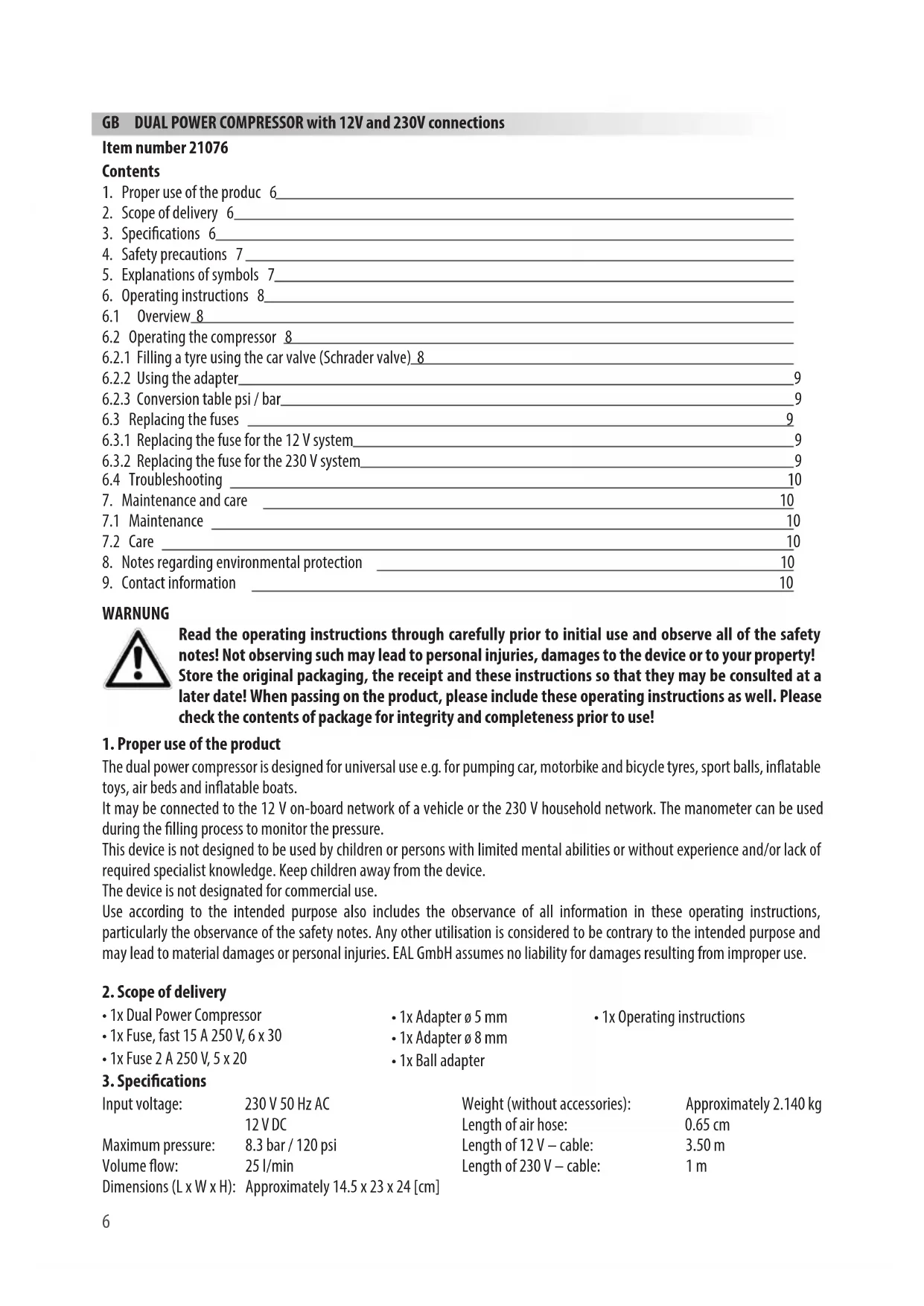
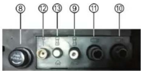
6.1 Overview
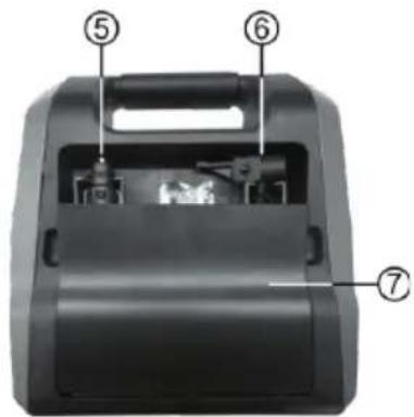
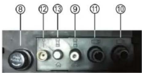
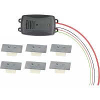
Figure 3: View of adapters and fuses
Figure 4: Side view. Figure 1: Front view. Figure 2: Rear view.
1 Carry handle, 2 Manometer, 3 On/Off switch for 12 V mode, 4 On/Off switch for 230 V mode, 5 Cable for 12 V vehicle connection (230 V cable not visible in image), 6 Valve connection for air hose, 7 Storage compartment lid, 8 Fuse holder (230 V)
9 Replacement fuse (12 V), 10 Adapter ∅ 8 mm, 11 Adapter ∅ 5 mm, 12 Ball adapter, 13 Replacement fuse (230 V), 14 Ventilation slots
6.2 Operating the compressor
In order to be able to work with the compressor, first take the air hose (Position 6 in the overview) and the connection cable (Position 5 in the overview) from the storage compartment (Position 7 in the overview).

Make sure that the compressor is switched off before connecting it (both switches, Positions 3 and 4 in the overview, may not be pressed).
6.2.1 Filling a tyre using the car valve (Schrader valve)
Open the lock on the valve connection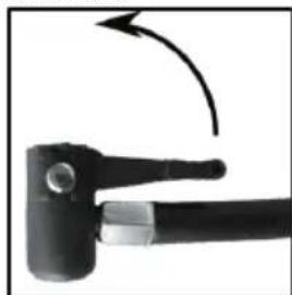
on the valve
Lock the valve connection. Place the valve connection. You can now fill the tyre using the compressor.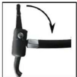

Figure 5, Figure 7, Figure 6, Figure 8
Connect the compressor to the power supply. Either to the 12V connection in your vehicle or to a 230V household connection.

CAUTION: Do not connect the compressor to both the 230 V household connection and the 12 V socket of your vehicle at the same time.
Switch the compressor on to fill. When connecting to a 12 V vehicle socket, press the right switch (Position 3 in the overview) on the front of the device. When connecting the compressor to the 230 V household network, press the left switch (Position 4 in the overview).
The manometer (Position 2 in the overview) is designed to monitor the air pressure. When the desired air pressure is reached, switch off the compressor by pressing the appropriate On/Off switch. Remove the valve connection in reverse order (Figures 8 – 5).

When filling, always pay attention to the correct air pressure (consult the operating instructions of your vehicle for information). The compressor is able to supply a pressure of up to 8.3 bar. If the pressure is too high, there is a risk of explosion and injury.

Never allow the compressor to operate for longer than 5 minutes without a pause, otherwise there is a risk of overheating. Switch the compressor off after 5 minutes of use and allow it to cool down fully (at least 20 minutes) before starting it up again.
Never leave the compressor to operate unattended

The compressor may discharge the battery of your vehicle if the motor is switched off.
If you use the compressor with the vehicle motor running, ensure good ventilation in the garage or hall. There is a risk of poisoning!
After filling a tyre, check the tyre pressure again using a separate air pressure tester (e.g. at a filling station, vehicle workshop).
6.2.2 Using the adapter
Open the lock of the valve connection (Figure 5). Insert the appropriate adapter for the required purpose into the valve connection. Lock the valve connection (Figure 7). Insert the adapter into the filling connection of your leisure equipment (ball, air bed etc.). Depending on version, it is possible that the adapter will need to be held firmly during the filling process. Now you can switch on the compressor and start the filling process. When the desired air pressure is reached, switch off the compressor by pressing the appropriate On/Off switch. Remove the adapter from the valve connection by proceeding in reverse order, as described above.
6.2.3 Conversion table psi / bar
The units are converted as follows:
1 psi = 0.069 bar 1 bar = 14.504 psi
6.3 Replacing the fuses
6.3.1 Replacing the fuse for the 12 V system
Rotate the tip (Position 17 in Figure 8) of the 12 V plug (Position 15 in Figure 8) anti-clockwise until it comes away from the plug and then remove. The fuse (Position 16 in Figure 8) is exposed and can be removed from the plug. Replace the fuse with another of the same strength and screw the tip back into the plug, Figure 8.

Figure 8: Fuse in 12 V plug
6.3.2 Replacing the fuse for the 230 V system
Open the storage compartment lid on the rear of the device. Remove the connection cable and the air hose. See also Figure 3 in the overview. Rotate the end cap (Position 18 in Figure 9) and remove. Remove the fuse (Position 19 in Figure 9) from the holder (Position 20 in Figure 9). Replace it with a new fuse of the same strength. Rotate the end cap back into the holder.
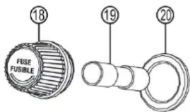
Figure 9: 230 V fuse in storage compartment
6.4 Troubleshooting
| Error | Possible cause Measure | |
| The compressor is not functioning | The connection cable is not connected correctly. | Check the cable connection and connect correctly. |
| When operating using a vehicle: No voltage to the on-board socket. | Switch on the ignition of your vehicle. Check the fuse for the on-board socket and replace if necessary. | |
| The fuses in the compressor have been triggered. | Replace the faulty fuse, see section 6.3 |
7. Maintenance and care
7.1 Maintenance: When used according to the instructions, the Dual Power Compressor is maintenance-free. Store the compressor in a dry, frost-free location.
7.2 Care: Switch the compressor off before cleaning, separate from the power supply. Clean the housing of the compressor with a soft, dry cloth. Do not use any aggressive cleaning agents or solvent-based cleaners. Never allow liquids to penetrate the housing.
8. Notes regarding environmental protection

Do not dispose of electrical devices with the household waste! Electrical and electronic scrap must be collected separately and disposed of in an environmentally responsible manner for recycling. Please contact your community or city administration regarding disposal options for electrical and electronic scrap.
9. Contact information
EAL GmbH

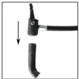

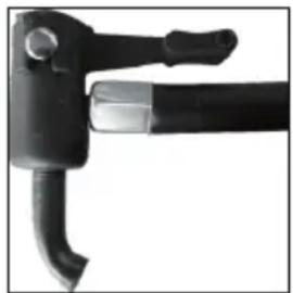

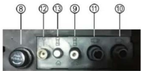
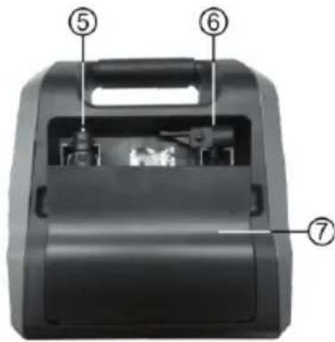
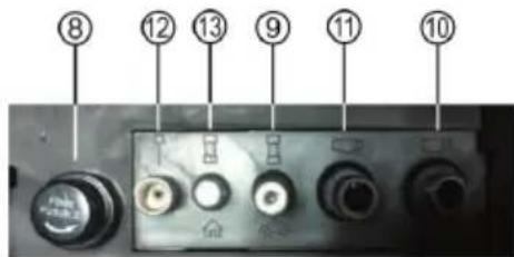
Figure 4: Side view
Figure 5 Figure 7 Figure 6 Figure 8


- GB DUAL POWER COMPRESSOR WITH 12V AND 230V CONNECTIONS
- ITEM NUMBER 21076
- CONTENTS
- WARNING
- PROPER USE OF THE PRODUCT
- SCOPE OF DELIVERY
- SPECIFICATIONS
- SAFETY PRECAUTIONS
- EXPLANATIONS OF SYMBOLS
- OPERATING INSTRUCTIONS
- 6.2 OPERATING THE COMPRESSOR
- 6.2.1 FILLING A TYRE USING THE CAR VALVE (SCHRADER VALVE)
- CAUTION: DO NOT CONNECT THE COMPRESSOR TO BOTH THE 230 V HOUSEHOLD CONNECTION AND THE 12 V SOCKET OF YOUR VEHICLE AT THE SAME TIME
- 6.2.2 USING THE ADAPTER
- 6.2.3 CONVERSION TABLE PSI / BAR
- 6.3 REPLACING THE FUSES
- 6.3.1 REPLACING THE FUSE FOR THE 12 V SYSTEM
- 6.3.2 REPLACING THE FUSE FOR THE 230 V SYSTEM
- 6.4 TROUBLESHOOTING
- MAINTENANCE AND CARE
- NOTES REGARDING ENVIRONMENTAL PROTECTION
- CONTACT INFORMATION
- EAL GMBH
Brand : EAL
Model : 21076
Category : Compressor