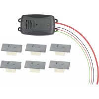
16277 - Ultrasonic repellent EAL - Free user manual and instructions
Find the device manual for free 16277 EAL in PDF.



| Product type | Ultrasonic marten repellent with high voltage |
| Brand | EAL |
| Model | 16277 |
| Dimensions (L x W x H) | Approx. 112 x 59 x 27 mm |
| Weight | Approx. 0.280 kg |
| Operating voltage | 12 V (vehicle battery) |
| Power consumption | 19 mA ±15% |
| Ultrasonic frequency | 23 kHz ±10% pulsed |
| High voltage | 250 - 350 V |
| Beam angle | 160° |
| Sound pressure | Max. 100 dB ±20% |
| Speaker | Piezo dome |
| Fuse | F 200 mA, L, 250 V |
| Function indicator | Red LED (on), yellow LED (high voltage flashing) |
| Number of high voltage plates supplied | 6 |
| Main functions | Pulsed ultrasonic emission and electric shock via contact plates to repel martens |
| Intended use | Protection of vehicles and campers against damage caused by martens |
| Mounting | In the engine compartment, away from heat and moving parts |
| Electrical connection | Red: + permanent (terminal 30), Black: ground (terminal 31), Green: + ignition (terminal 15) |
| Maintenance | Clean the contact plates with a damp cloth after removing the fuse |
| Cleaning | Use a soft, damp cloth, no aggressive cleaners or solvents |
| Safety | Disconnect battery before mounting; do not allow children to use; turn off before maintenance |
| Spare parts and repairability | Replaceable fuse (F 200 mA, L, 250 V); contact plates available as an option |
| General information | Manufactured by EAL GmbH, 42115 Wuppertal, Germany |
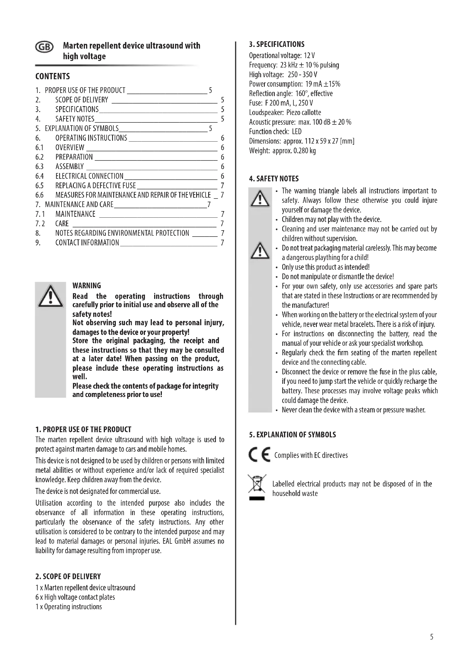
| Package contents | 1 device, 6 contact plates, 1 instruction manual |
Frequently Asked Questions - 16277 EAL
User questions about 16277 EAL
0 question about this device. Answer the ones you know or ask your own.
Ask a new question about this device
Download the instructions for your Ultrasonic repellent in PDF format for free! Find your manual 16277 - EAL and take your electronic device back in hand. On this page are published all the documents necessary for the use of your device. 16277 by EAL.
USER MANUAL 16277 EAL
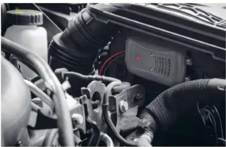
Marten repellent device ultrasound with high voltage
Operating instructions .... 5

Réf. 16277
WARNUNG
Bild 1: Übersicht
6.2 VORBEREITUNG
Bild 2: Montage
Read the operating instructions through carefully prior to initial use and observe all of the safety notes!
Not observing such may lead to personal injury, damages to the device or your property!
Store the original packaging, the receipt and these instructions so that they may be consulted at a later date! When passing on the product, please include these operating instructions as well.
Please check the contents of package for integrity and completeness prior to use!
1. PROPER USE OF THE PRODUCT
The marten repellent device ultrasound with high voltage is used to protect against marten damage to cars and mobile homes.
This device is not designed to be used by children or persons with limited metal abilities or without experience and/or lack of required specialist knowledge. Keep children away from the device.
The device is not designated for commercial use.
Utilisation according to the intended purpose also includes the observance of all information in these operating instructions, particularly the observance of the safety instructions. Any other utilisation is considered to be contrary to the intended purpose and may lead to material damages or personal injuries. EAL GmbH assumes no liability for damage resulting from improper use.
2. SCOPE OF DELIVERY
1 x Marten repellent device ultrasound
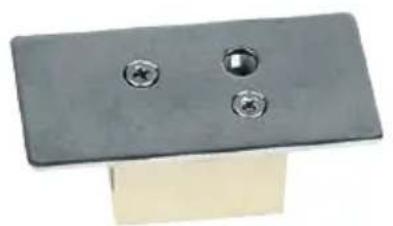
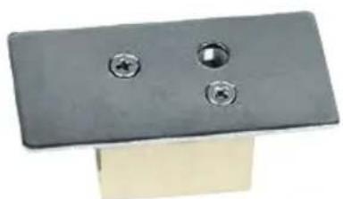
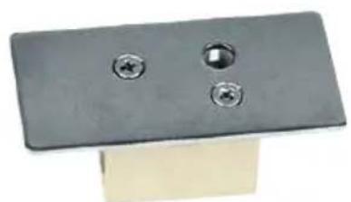
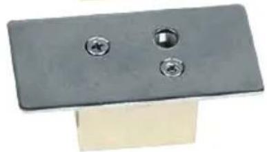
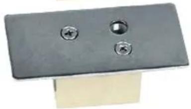
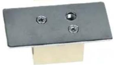
6 x High voltage contact plates
1 x Operating instructions
3. SPECIFICATIONS
Operational voltage: 12 V
Frequency: 23 kHz ± 10 % pulsing
High voltage: 250 - 350 V
Power consumption: 19 mA ±15%
Reflection angle: 160°, effective
Fuse: F 200 mA, L, 250 V
Loudspeaker: Piezo callotte
Acoustic pressure: max. 100 dB ± 20 %
Function check: LED
Dimensions: approx. 112 x 59 x 27 [mm]
Weight: approx. 0.280 kg
4. SAFETY NOTES

- The warning triangle labels all instructions important to safety. Always follow these otherwise you could injure yourself or damage the device.
• Children may not play with the device. - Cleaning and user maintenance may not be carried out by children without supervision.
- Do not treat packaging material carelessly. This may become a dangerous plaything for a child!
• Only use this product as intended! - Do not manipulate or dismantle the device!
- For your own safety, only use accessories and spare parts that are stated in these Instructions or are recommended by the manufacturer!
- When working on the battery or the electrical system of your vehicle, never wear metal bracelets. There is a risk of injury.
- For instructions on disconnecting the battery, read the manual of your vehicle or ask your specialist workshop.
- Regularly check the firm seating of the marten repellent device and the connecting cable.
- Disconnect the device or remove the fuse in the plus cable, if you need to jump start the vehicle or quickly recharge the battery. These processes may involve voltage peaks which could damage the device.
- Never clean the device with a steam or pressure washer.
5. EXPLANATION OF SYMBOLS

Complies with EC directives
Labelled electrical products may not be disposed of in the household waste
6. OPERATING INSTRUCTIONS
6.1 OVERVIEW
1 Control lamp high voltage
2 Control lamp operation
3 Loudspeaker opening
4 Mounting lugs
5 Control cable, green
6 Plus (+) cable, red
7 Minus (-) cable, black
8 High voltage cable
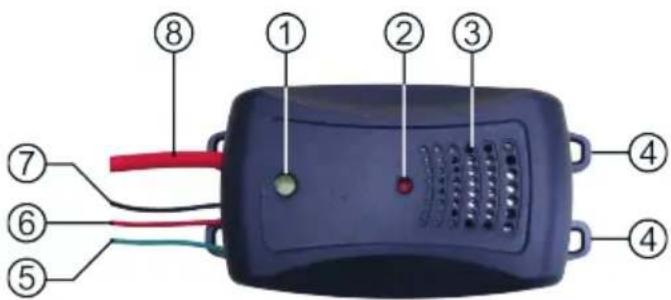
Figure 1: Overview
6.2 PREPARATION
Clean the engine compartment thoroughly or use the primer spray for removing marten scent marks, item number: 16265 before installing the ultrasound marten repellent device. We also recommend cleaning the underside of the vehicle and the site on which it stands.

CAUTION
Before starting with the installation of the ultrasound marten repellent device, read the instructions in the manual of your vehicle regarding disconnecting the battery. Disconnecting the battery may result in information in the on-board computer and radio settings being lost.
6.3 ASSEMBLY
Install the ultrasound marten repellent device in such a way that the sound is able to spread freely, similar to the light cone of a torch. Select a position, fig.2, that is as high up as possible in the engine compartment to prevent the risk of influence from dirt and water. Ensure a good distance is left between the device and heat sources such as the exhaust, catalytic converter and rotating parts. Make sure that the fuse in the connecting cable is easily accessible. In very tight engine compartments, it may be necessary to install multiple martin repellent devices since the ultrasound can be shielded considerably by obstacles.
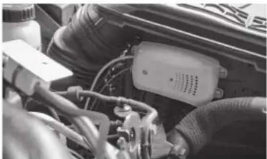
Figure 2: Mounting
Lay the high-voltage cable in such a way that there are bare metal parts with a ground connection nearby, (fig. 3). The repelling effect is only guaranteed if the marten touches a contact plate and grounded parts at the same time.
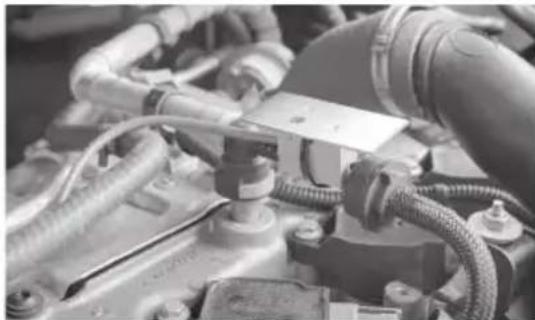
Figure 3: High voltage cable
6.4 ELECTRICAL CONNECTION
Disconnect the battery.

Lay the cables so that they are not under tension and cannot be kinked or crushed. Keep away from heat sources such as exhaust, catalytic converter and rotating parts. Secure the cables well and safely.
Plus (+) connecting cable, red (6) to permanent plus (terminal 30)
Minus (-) connection cable, black (7) to earth (terminal 31)
Control cable, green (5) to ignition plus (terminal 15)
The control cable is connected to the ignition plus and ensures that the unit switches off when the vehicle is started. If you do not connect this cable, the unit is in continuous operation. This continuous operation is not permitted within the scope of the German Road Traffic Licensing Regulations (StVZO).
Remove the screw above the hole for the high-voltage cable from each contact plate (Fig. 4).
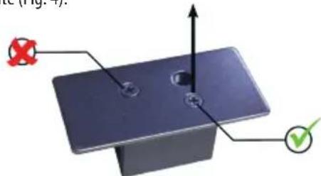
Figure 4: Remove screw
Pass the high-voltage cable through the small hole in the insulator on all contact plates (Fig. 5).
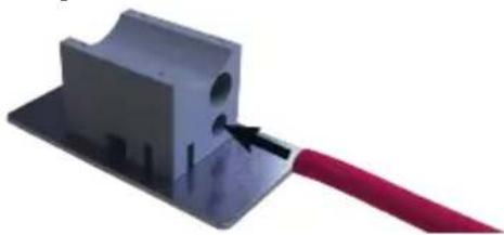
Figure 5: High-voltage cable through insulator
When you have fixed all contact plates, put the screws back in (picture 6). Screw the screws all the way in. The screw penetrates the insulation of the high-voltage cable. This makes an electrical connection between the cable and the contact plate.

Figure 6: Screw in the screw
Reconnect the battery and check that the terminals are tight. The marten repellent is now in operation. The operating indicator light (position 2 in the overview) lights up red, the high-voltage indicator light (position 1 in the overview) lights up yellow at intervals.

Ultrasound cannot be perceived by humans. Use the indicator light as a guide when checking the function.

CAUTION
High voltage is now applied to the contact plates.
Make sure that the installation of the marten repellent ultrasonic does not interfere with any other functions of the vehicle.
Check that the marten repellent is switched off when the ignition is switched on, the indicator lights go out.

CAUTION
When the vehicle stands for a long time, the battery may discharge.
6.5 REPLACING A DEFECTIVE FUSE
Unscrew the housing of the fuse holder in the plus cable. Replace the defective fuse with a new, fuse of the same type F 200 mA, L, 250V. Screw the fuse holder back together again.

Figure 7: Replace fuse
6.6 MEASURES FOR MAINTENANCE AND REPAIR OF THE VEHICLE

Inform the workshop about the installation of the marten repellent device.
Switch off the Marder repellent unit by removing the fuse (see section 6.5) before starting maintenance or repair work.
7. MAINTENANCE AND CARE

Touching the contact plates with a damp cloth will cause an electric shock when the unit is switched on.
Therefore, switch off the marten repellent device by Remove the fuse (see section 6.5) before starting work.
7.1 MAINTENANCE
The marten repellent itself is maintenance-free when used as intended. Regularly check the device, the high-voltage cables and the contact plates for firm and correct fit.
7.2 CARE
Keep the bare surfaces of the contact plates clean.
Use a soft, maximally damp cloth for this purpose. Do not use any sharp cleaners or cleaners containing solvents. The frequency of cleaning depends on the weather, season and road surface. the road surface.
Replace the fuse after completing the work.
8. NOTES REGARDING ENVIRONMENTAL PROTECTION

Do not dispose of electrical devices with the household waste! Electrical and electronic scrap must be collected separately and disposed of in an environmentally responsible manner for recycling. Please contact your community or city administration regarding disposal options for electrical and electronic scrap.
9. CONTACT INFORMATION
EAL GmbH
42115 Wuppertal, Germany
+49 (0)202 42 92 83 0
AVERTISSEMENT
Figure 1: Sommaire
6.2 PRÉPARATION
Figure 2: Montage
Figure 6 : Visser la vis
Figure 7: Remplacer le fusible
6.6 MESURES À PRENDRE LORS DE L'ENTRETIEN ET DE LA RÉPARATION DU VÉHICULE

WAARSCHUWING
EAL GmbH



- WARNUNG
- 6.2 VORBEREITUNG
- PROPER USE OF THE PRODUCT
- SCOPE OF DELIVERY
- SPECIFICATIONS
- SAFETY NOTES
- EXPLANATION OF SYMBOLS
- OPERATING INSTRUCTIONS
- 6.1 OVERVIEW
- 6.2 PREPARATION
- CAUTION
- 6.3 ASSEMBLY
- 6.4 ELECTRICAL CONNECTION
- 6.5 REPLACING A DEFECTIVE FUSE
- 6.6 MEASURES FOR MAINTENANCE AND REPAIR OF THE VEHICLE
- MAINTENANCE AND CARE
- 7.1 MAINTENANCE
- 7.2 CARE
- NOTES REGARDING ENVIRONMENTAL PROTECTION
- CONTACT INFORMATION
- EAL GMBH
- AVERTISSEMENT
- 6.2 PRÉPARATION
- 6.6 MESURES À PRENDRE LORS DE L'ENTRETIEN ET DE LA RÉPARATION DU VÉHICULE
- WAARSCHUWING
Brand : EAL
Model : 16277
Category : Ultrasonic repellent