CM E1 - Multimeter BENNING - Free user manual and instructions
Find the device manual for free CM E1 BENNING in PDF.
| Product type | Earth ground clamp meter |
| Brand | BENNING |
| Model | CM E1 |
| Category | Multimeter |
| Dimensions (L x W x H) | 276 x 100 x 47 mm |
| Weight | Approx. 750 g (with batteries) |
| Power supply | 9 V battery (IEC 6 LR 61) |
| Jaw opening | 38 mm |
| Display | Digital LCD, 4 digits (9999 counts) |
| Measurement functions | Earth loop resistance (0.025 Ω - 1500 Ω), AC current / leakage current (0.300 mA - 35.00 A) |
| Measurement accuracy (resistance) | ± (1.5% to 20%) depending on range |
| Measurement accuracy (current) | ± (2.0% to 3.0%) depending on range |
| Special functions | Data logging (116 values), HI/LO alarm thresholds, HOLD function, auto power off (APO), self-calibration |
| Overvoltage category | CAT III 300 V |
| Pollution degree | 2 |
| Protection rating | IP30 |
| Operating temperature | 0 °C to 50 °C (humidity < 85%) |
| Storage temperature | -20 °C to +60 °C (humidity < 75% without batteries) |
| Standards | DIN VDE 0411 Part 1/EN 61010-1, DIN VDE 0413 Part 5/EN 61557-5 |
| Maintenance | Cleaning with dry cloth and mild detergent; avoid solvents |
| Repairability | Repair by qualified personnel only; calibration recommended annually |
| Package contents | Device, carrying case, reference resistive loop, 9 V battery, instruction manual |
Frequently Asked Questions - CM E1 BENNING
User questions about CM E1 BENNING
0 question about this device. Answer the ones you know or ask your own.
Ask a new question about this device
Download the instructions for your Multimeter in PDF format for free! Find your manual CM E1 - BENNING and take your electronic device back in hand. On this page are published all the documents necessary for the use of your device. CM E1 by BENNING.
USER MANUAL CM E1 BENNING
text_image
J I G F E REC NO. NOISE H 8.8.8.8 Ω C A B Ω m VA AP K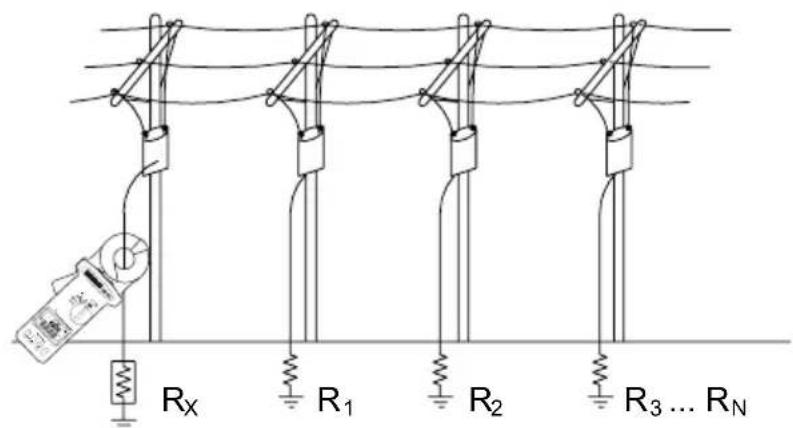
text_image
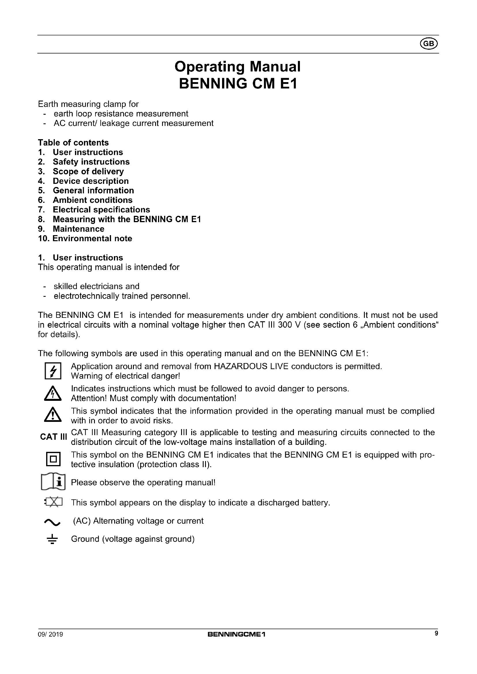
Rx R1 R2 R3 ... RN
text_image
RI R₁ R₂ ... Rₙ Rₓ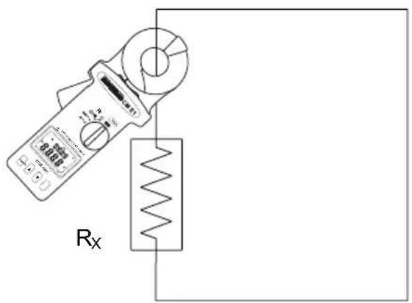
text_image
RxFig. 3: Earth loop resistance measurement
text_image
Technical diagram showing a measurement device connected to an electric motor, with digital display and control buttons visible.Bild 4: Wechselstrom-/ Ableitstrommessung
Fig. 4: AC current/leakage current measurement
Fig. 4: Mesure du courant alternatif / du courant de fuite
Fig. 4: Wisselstroom-/ lekstroommeting
natural_image
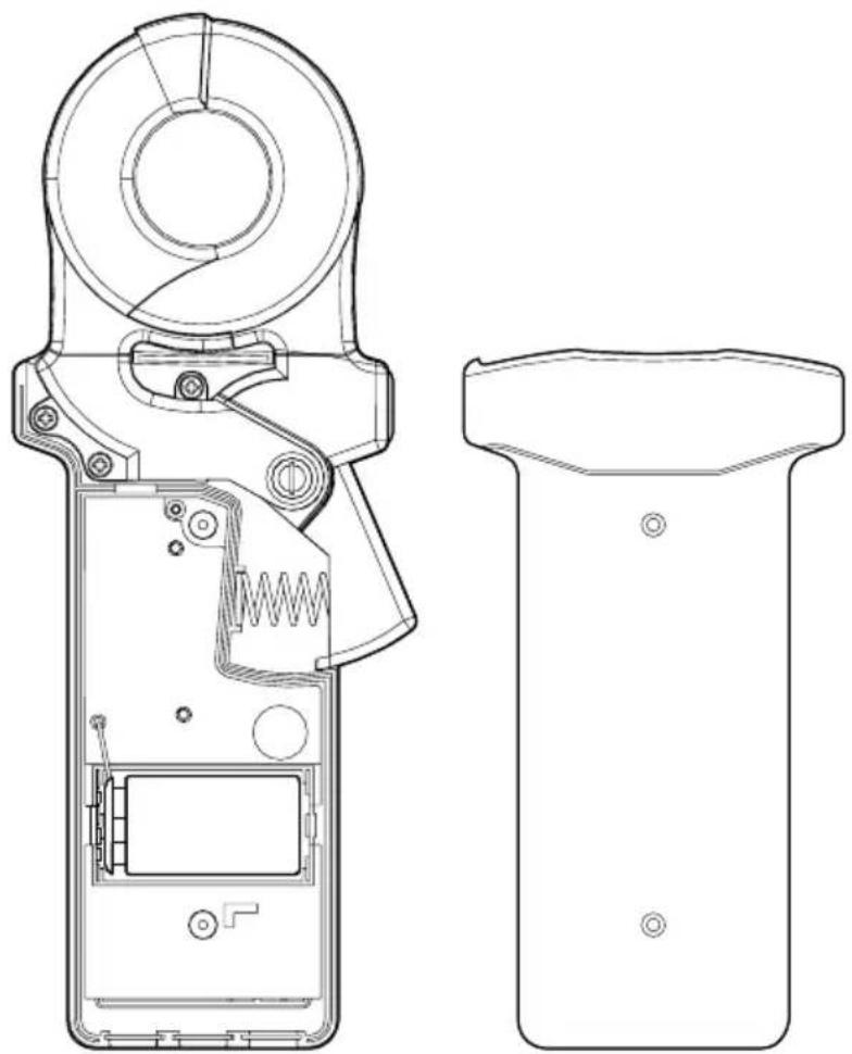
Technical line drawing of a handheld device with internal components and external casing (no text or symbols)Bild 5: Batteriewechsel
Fig. 5: Battery replacement
Fig. 5: Remplacement de la pile
Fig. 5: Vervanging van de batteri
$$ R s = E / I \quad w o b e i g i l t: \quad R s = R x + (R 1 I I R 2 \dots I I R N) + R b + R I $$
Earth measuring clamp for
- earth loop resistance measurement
- AC current/ leakage current measurement
Table of contents
- User instructions
- Safety instructions
- Scope of delivery
- Device description
- General information
- Ambient conditions
- Electrical specifications
- Measuring with the BENNING CM E1
- Maintenance
- Environmental note
1. User instructions
This operating manual is intended for
- skilled electricians and
- electrotechnically trained personnel.
The BENNING CM E1 is intended for measurements under dry ambient conditions. It must not be used in electrical circuits with a nominal voltage higher than CAT III 300 V (see section 6 „Ambient conditions“ for details).
The following symbols are used in this operating manual and on the BENNING CM E1:

Application around and removal from HAZARDOUS LIVE conductors is permitted. Warning of electrical danger!

Indicates instructions which must be followed to avoid danger to persons. Attention! Must comply with documentation!

This symbol indicates that the information provided in the operating manual must be complied with in order to avoid risks.

CAT III Measuring category III is applicable to testing and measuring circuits connected to the distribution circuit of the low-voltage mains installation of a building.

This symbol on the BENNING CM E1 indicates that the BENNING CM E1 is equipped with protective insulation (protection class II).

Please observe the operating manual!

This symbol appears on the display to indicate a discharged battery.

(AC) Alternating voltage or current

Ground (voltage against ground)
2. Safety instructions
The instrument is built and tested in accordance with
DIN VDE 0411 Part 1/ EN 61010-1
DIN VDE 0411 Part 2-032/EN 61010-2-032
and has left the factory in perfectly safe technical condition.
To preserve this condition and to ensure safe operation of the device, the user must observe the notes and warnings given in these instructions at all times. Improper handling and non-observance of the warnings might involve severe injuries or danger to life.

WARNING! Be extremely careful when working with bare conductors or main line carrier! Contact with live conductors will cause an electric shock!

Before starting the current clamp multimeter, always check the device as well as all measuring leads for damages.
If it can be assumed that safe operation is no longer possible, switch the device off immediately and secure it against unintended operation.
Safe operation can be assumed to be no longer possible, if
- the device exhibit visible damages,
- the device no longer works,
- the device has been stored under unfavourable conditions for a longer period of time,
- the device was exposed to extraordinary stress during transport, or
- if the device is are exposed to moisture.

Maintenance:
Do not open the multimeter, because it contains no components which can be repaired by the user. Repair and service must be carried out by qualified personnel only!

Cleaning:
Regularly wipe the housing by means of a dry cloth and cleaning agent. Do not use any polishing agents or solvents!
3. Scope of delivery
The scope of delivery of the BENNING CM E1 comprises:
3.1 One BENNING CM E1
3.2 One transport case with shoulder strap (10217859)
3.3 One reference earth resistance loop (10217860)
3.4 One 9 V block battery (IEC 6 LR 61)
3.5 One operating manual
Parts subject to wear:
- The BENNING CM E1 is supplied by means of one 9 V block battery (IEC 6 LR61).
4. Device description
see figure 1: Appliance front face
The display and operating elements shown in figure 1 are designated as follows:
① Measuring clamp, for clamping the earthing conductor/earth connection
② HOLD key, storage of the indicated measured value
3 Rotary switch, for selecting the measurement function
4 Digital display
⑤ REC key, for starting the data logger/storage
6 ▼ key, decreases the setting value
⑦ Opening lever, for opening and closing the current prongs
8 ▲ key, increases the setting value
9 FUNC key, function key for selecting alarm thresholds, sampling rate and storage location number
see figure 2: Digital display
The symbols shown in fig. 2 are designated as follows:
A Secondary display, for function selection and storage location number
B Digital display, for measured value, alarm threshold, sampling rate
© Ω Ohm, unit of loop resistance measurement
D mA, unit of current/ leakage current measurement
E ,hop resistance measurement with acoustic alarm function
F NOISE, detection of interfering signals, measurement might be affected
G, measuring clamp is not closed correctly
H battery status indication
① NO., storage location number
J REC, data logger is enabled
K AP, automatic switch-off is enabled (APO active)
5. Functions of the earth measuring clamp
5.1 General information
5.1.1 The digital display B is a 4-digit LC display with a font size of 11 mm and a decimal point. The highest numerical value to be displayed is 9999.
5.1.2 The range exceedance is indicated by „OL“. Attention, no other indication and warning in case of overload!
5.1.3 The rotary switch ③ is intended for selecting the measuring function. The selection of the measuring range is automatic.
5.1.4 HOLD key function: The measuring result can be stored by pressing the HOLD key ②. The "H" symbol simultaneously appears on the display ④.
5.1.5 REC key function: for starting the data logger or storing a measured value in the internal memory
5.1.6 FUNC function key: function key for selecting the alarm thresholds "HI" (high), "LO" (low), the sampling rate "SEC" (seconds) and storage location number "NO." (1-116)
5.1.7 The nominal measuring rate of the BENNING CM E1 is 2 measurements per second.
5.1.8 The BENNING CM E1 is switched on and off with the rotary switch ③. Shutdown position "OFF".
5.1.9 The BENNING CM E1 switches off automatically after approx. 4 min. to 6 min. (APO, Auto-Power-Off is enabled if the "AP" symbol K is shown on the display ④). It switches on again as soon as the rotary switch ③ is switched on again from switch position "OFF". Automatic switch-off can be deactivated by pressing the FUNC key and by simultaneously switching on the BENNING CM E1 from the switching position "OFF". The symbol AP K disappears from the display ④.
5.1.10 The BENNING CM E1 is supplied by a fitted 9 V block battery (IEC 6 LR 61).
5.1.11 If the battery voltage drops below the specified operating voltage of the BENNING CM E1, then a battery symbol Ⓗ appears in the display 4.
5.1.12 The battery life depends on the measuring function used and is intended for approx. 3000 measurements.
5.1.13 Temperature coefficient of the measured value: 0.1 x (stated measuring accuracy)/ °C < 18 °C or > 28 °C, related to the value for the reference temperature of 23 °C.
5.1.14 Dimensions of unit (length x width x height) = 276 x 100 x 47 mm Weight of unit: approx. 750 g (incl. battery)
5.1.15 Widest prong opening: 38 mm
5.2 Setting the alarm thresholds of the earth loop resistance
To measure the earth loop resistance, an upper (HI) and lower (LO) alarm threshold can be set. Use the rotary switch ③ to select the function Ω and press the FUNC key ⑨ until the "HI" symbol or "LO" symbol appears on the secondary display A. By pressing the ▼ key ⑥ and the ▲ key ⑧, the alarm threshold can be set from 0 ohms to 1510 ohms or "OL" respectively. After having set one alarm threshold or both, press the FUNC key ⑨ until the symbols on the secondary display A disappear.
As soon as the rotary switch position +· is selected, the earth measuring clamp compares the displayed value with the upper and lower alarm thresholds.
If the displayed value is higher than the upper alarm threshold, a pulsating acoustic signal is emitted and the "HI--" symbol is displayed.
If the displayed value is lower than the lower alarm threshold, a pulsating acoustic signal is emitted and
the "LO--" symbol is displayed.

Note:
- To disable the alarm thresholds, set the upper alarm (HI) to "OL" and the lower alarm (LO) to "0".
- The upper alarm (HI) cannot be lower than the lower alarm (LO), and the lower alarm (LO) cannot be higher than the upper alarm (HI).
- When the data logger is enabled, the acoustic alarm function is disabled.
- The alarm thresholds set remain stored until they are changed the next time.
5.3 Data logger function
The data logger function allows the automatic and manual storage of series of measurements (Funktion / ), mA/ A) with a predefined measuring interval (sampling rate) and up to 116 measured values. The measuring interval can be set from 1 s to 255 s. The measured values can be read out later by means of the display 4.
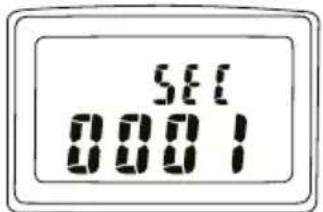
5.3.1 Setting the sampling rate
Press the FUNC key ⑨ several times until the “SEC” symbol appears on the secondary display A. The digital display B shows the sampling rate in seconds. Use the ▼ key ⑥ und the ▲ key ⑧ to set the sampling rate from 1 s to 255 s. Press and hold the keys to accelerate the setting process. Then, press the FUNC key ⑨ several times until the symbols on the secondary display A disappear.
Note:
To store only a single measured value, select a sampling rate of 0 s. Each time the REC key ⑤ is pressed, another measured value is stored in the internal memory and the storage location number is briefly shown on the secondary display ⚠.
text_image
SET 00015.3.2 Starting and stopping the data logger
Press the REC key ⑤ to start the data logger. At the same time, the REC symbol ① appears on the digital display ④. The measured values are stored in the internal memory taking into account the sampling rate set. The data logger can be stopped by pressing the REC key ⑤ and stops automatically as soon as the measured value memory is full. The REC icon ① on the digital display ④ disappears.
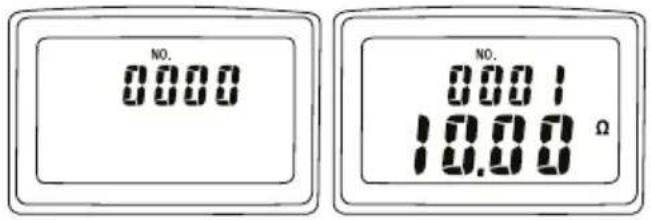
5.3.3 Calling measured values
Press the FUNC key ⑨ several times until the "NO." symbol ① appears on the digital display ④. By pressing the ▼ key ⑥ and the ▲ key ⑧, the storage location number is selected via the secondary display ④ and the corresponding measured value is shown on the digital display ⑧.
text_image
NO. 0.000 NO. 10.00 Ω5.3.4 Deleting the measured value memory
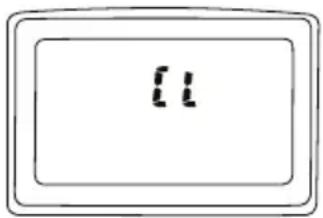
Delete the complete measured value memory by pressing the REC key ⑤ and by simultaneously switching on the BENNING CM E1 from the switching position "OFF". The "CL" symbol being shown on the display ④ means that the measured value memory has been deleted.
text_image
115.4 Functional principle of earth loop resistance measurement
Earth loop resistance measurement is one of the methods of measuring the earth resistance without using rods. It offers the advantage that no additional probes/auxiliary earth electrodes have to be installed and the earth connection itself does not have to be disconnected. The method is used, among other things, in electrical installations with several parallel earthing connections, such as overhead line networks with pole-type earth electrodes, lightning protection and street lighting systems.
The BENNING CM E1 has a specially shielded measuring clamp ① with integrated excitation winding and sensor winding. The excitation winding induces a current flow in the clamped earthing conductor/earth connection via a defined AC voltage E. The current flow I is measured via the sensor winding and the resistance of the entire earth loop Rs is calculated and displayed via the BENNING CM E1.
$$ R s = E / I \quad \text { provided that: } \quad R s = R x + (R 1 \text { II } R 2 \dots \text { II } R N) + R b + R l $$
$$ \text { with } (R 1 \text { II } R 2 \dots \text { II } R n) < < R x \text { and } (R b + R I) < R x \quad \text { results in } R s \approx R x $$
This means that the earth loop resistance Rs measured by the BENNING CM E1 is always higher than the searched earth loop resistance Rx. The higher the number of parallel earth connections, the more accurate the displayed value Rs corresponds to the searched earth resistance Rx. If the displayed resistance value is too high, check the earth connection.
Rs: Earth loop resistance (entire earth loop)
Rx: Searched earth resistance
R1 ... RN: Parallel earth connections, negligible the higher the number
Rb: Resistance of the soil, usually <1 Ω
RI: Resistance of the earthing lines, usually <1 Ω
see figure 3: Earth loop resistance measurement
6. Ambient conditions
- The BENNING CM E1 is intended for measurements under dry ambient conditions
- Maximum barometric height for measurements: 2000 m
- Overvoltage category / installation category: IEC 60664/ IEC 61010 → 300 V category III
- Contamination class: 2 according to EN 61010-1
- Protection class: IP 30 (DIN VDE 0470-1, IEC/ EN 60529)
IP 30 means: Protection against access to dangerous parts and protection against solid impurities of a diameter > 2.5 mm, (3 - first index). No protection against water, (0 - second index).
- Operating temperature and relative humidity:
For operating temperatures from 0 °C to 50 °C: relative air humidity lower than 85 %, noncondensing.
- Storage temperature: The BENNING CM E1 can be stored at temperatures between - 20 °C and + 60 °C, at a relative air humidity lower than 75 % without batteries.
7. Electrical specifications
Note: The measuring accuracy is specified as the sum of:
- a relative part of the measured value and
- a number of digits (i.e. counting steps of the last digit).
This measuring accuracy applies to temperatures from 23 ^ ± 5 ^ and a relative air humidity lower than 80 %.
7.1 Loop resistance ranges
| Measuring range Resolution Measurement accuracy | *1 | ||
| 0.025 Ω - 0.250 Ω 0.002 Ω ± (1.5 % ± 0.05 Ω) | |||
| 0.251 Ω - 1.000 Ω 0.02 Ω ± (1.5 % ± 0.05 Ω) | |||
| 1.001 Ω -10.00 Ω 0.02 Ω ± (1.5 % ± 0.1 Ω) | |||
| 10.01 Ω - 50.00 Ω 0.04 Ω ± (2.0 % ± 0.3 Ω) | |||
| 50.01 Ω -100.0 Ω 0.04 Ω ± (2.0 % ± 0.5 Ω) | |||
| 100.1 Ω - 200.0 Ω 0.4 Ω ± (3.0 % ± 1.0 Ω) | |||
| 200.1 Ω - 400.0 Ω 2 Ω ± (5.0 % ± 5 Ω) | |||
| 400.1 Ω - 600.0 Ω 5 Ω | ± (10 % ± 10 Ω) | ||
| 600.1 Ω - 1500 Ω | 20 Ω | ± (20 %) | |
*1 valid for purely ohmic resistances, external magnetic field <30 A/m, external electric field <1 V/m
Measuring frequency: 3.333 kHz
Accuracy of the reference resistance loop: approx. ± 1 %
| Alarm threshold Range | Resolution | |
| Upper alarm (HI) | 0 - 1510 Ω | 1 Ω |
| Lower alarm (LO) | 0 - 1510 Ω | 1 Ω |
7.2 AC current/ leakage current
The measured value is obtained and displayed as real r.m.s. value (True RMS, AC coupling). Its calibration is adapted to sinusoidal curves. In case of deviations from this curve shape, the accuracy of the displayed value decreases. Crest factor < 3.5
| Measuring range Resolution | Measurement accuracy in frequency range 50 Hz - 60 Hz | |
| 0.300 mA - 1.000 mA | 0.001 mA | ± (2.0 % ± 0.05 mA) |
| 1.00 mA - 10.00 mA | 0.01 mA | ± (2.0 % ± 0.03 mA) |
| 10.0 mA - 100.0 mA | 0.1 mA | ± (2.0 % ± 0.3 mA) |
| 100 mA - 1000 mA | 1 mA | ± (2.0 % ± 3 mA) |
| 0.200 A - 4.000 A | 0.001 A | ± (2.0 % ± 0.03 A) |
| 4.00 A - 35.00 A | 0.01 A | ± (3.0 % ± 0.03 A) |
Overload protection: 100 A
8. Measuring with the BENNING CM E1
8.1 Preparation for measuring
Operate and store the BENNING CM E1 at the specified storage and operating temperatures only! Do not permanently expose the device to sunlight.
- Strong sources of interference in the vicinity of the BENNING CM E1 might involve unstable readings and measuring errors.
8.2 Loop resistance measurement

Do not exceed the maximum permitted voltage with respect to earth potential! Electrical danger!
- Open the measuring clamp and check whether the metallic contact surfaces inside the clamp are free of dust and contamination.
- Let the jaws of the measuring clamp snap together several times (open and close them) in order to establish a safe contact.
-
Use the rotary switch ③ to select the function (loop resistance) or ( + 1)) (loop resistance with alarm). Wait until the end of the self-calibration (CAL 7, CAL 6, ..., CAL 2, CAL 1) is confirmed by an acoustic signal and the ".OL" symbol appears on the digital display ⑧.
-
Open the measuring clamp and clamp the earthing conductor/earth connection to be tested. Let the jaws of the measuring clamp snap together again several times.
- The measured value of the earth loop resistance can be read on the digital display B.
Note:
- During self-calibration, do not place the measuring clamp ① around a conductor or open the measuring clamp.
- If self-calibration does not stop, check whether the metallic contact surfaces inside the clamp are free of dust and contamination.
- If interfering signals (current >3 A, voltage >30 V) are detected during the measurement, the "NOISE" symbol F appears on the digital display ④ and the measurement might be affected.
- If the clamp was not closed correctly during the measurement, the C symbol G appears on the digital display 4.
see fig. 3: Earth loop resistance measurement
8.3 AC current/ leakage current measurement

Do not exceed the maximum permitted voltage with respect to earth potential! Electrical danger!
- Use the rotary switch ③ of the BENNING CM E1 to select the desired function mA or A.
- Open the measuring clamp ① and clamp the earthing conductor/earth connection to be tested.
- The measured value of the leakage current can be read on the digital display Ⓑ.
see figure 4: AC current/ leakage current measurement
9. Maintenance

Before opening the BENNING CM E1, strictly observe that the device is free of voltage! Electrical danger!
9.1 Securing the device
Under certain circumstances, safe operation of the BENNING CM E1 might no longer be ensured, e.g. in case of:
- visible damage of the casing.
- incorrect measuring results,
- recognizable consequences of prolonged storage under inadmissible conditions and
- recognizable consequences of extraordinary stress due to transport.
In such cases, immediately switch off the BENNING CM E1, disconnect it from the measuring points and secure it against further use.
9.2 Cleaning
Clean the exterior of the device with a clean dry cloth (exception: special cleaning wipers). Do not use any solvents and/or abrasives to clean the device. Make sure that the battery compartment and the battery contacts are not contaminated by leaking battery electrolyte.
If there are electrolyte contamination or white deposits in the area of the battery or the battery compartment, clean these areas as well by means of a dry cloth.
9.3 Battery replacement

Before opening the BENNING CM E1, strictly observe that the device is free of voltage! Electrical danger!
The BENNING CM E1 is fed by a 9 V block battery.
The battery must be replaced (see fig. 5) when the battery symbol ☐ appears in the display ④. When the BENNING CM E1 is switched on, a battery test is carried out.
Proceed as follows to replace the battery:
- Switch off the BENNING CM E1.
- Put the BENNING CM E1 face down and unscrew the screws of the bottom part of the housing.
- Lift the bottom part of the housing off the front part.
-
Lift the discharged battery from the battery compartment and disconnect the battery supply lines from the battery.
-
The new battery have to be connected to the battery supply lines, and arrange these such that they are not crushed between the housing parts. Then, insert the new battery into the front part at the provided place.
- Lock the bottom part of the housing into place on the front part and tighten the screws.
see figure 5: Battery replacement

Make your contribution for environmental protection! Do not dispose of discharged batteries via the household waste. Instead, return them to a collecting point for discharged batteries or spezial waste. Please look for information in your community's facilities.
9.4 Calibration
Benning guarantees compliance with the technical and accuracy specifications stated in the operating manual for the first 12 months after the delivery date.
To maintain accuracy of the measuring results, the device must be recalibrated in regular intervals by our factory service. We recommend recalibrating the device once a year. For this purpose, send the device to the following address:
10. Environmental note

At the end of product life, dispose of the unserviceable device via appropriate collecting facilities provided in your community.