Titanium 230 ACDC FV - Welding machine GYS - Free user manual and instructions
Find the device manual for free Titanium 230 ACDC FV GYS in PDF.

| Product type | TIG AC/DC and MMA welding machine |
| Brand | GYS |
| Model | Titanium 230 ACDC FV |
| Power supply | Single-phase 110-240 V, 50-60 Hz (Flexible Voltage) |
| TIG DC welding current | 5 - 230 A |
| TIG AC welding current | 10 - 230 A |
| MMA welding current | 10 - 230 A |
| TIG welding modes | Standard, Pulsed, FastPulse, Spot, Tack, Multi-Spot, Multi-Tack, Synergic, Wizard, AC Mix, E-TIG |
| MMA welding modes | Standard, Pulsed, AC |
| Starting type | Lift, HF, Touch HF |
| VRD function (Voltage Reduction Device) | Yes, internally activatable |
| User interface | Color screen HMI with knobs and push buttons |
| Connectivity | USB, remote control connector, cooling unit connector |
| Thermal protection | Yes, with automatic detection |
| Protection rating | IP23 |
| Standards | IEC 61000-3-11, IEC 61000-3-12 |
| Generator compatibility | Yes (subject to voltage and frequency conditions) |
| Cooling | Smart ventilation, external cooling unit option (KOOLWELD 1) |
| Warranty | 2 years parts and labor |
| Maintenance | Regular dusting with compressed air, checking connections, annual maintenance by qualified personnel |
| Available spare parts | Electrodes, torches, nozzles, dust filter (ref. 046580), cooling unit (ref. 070820) |
Frequently Asked Questions - Titanium 230 ACDC FV GYS
User questions about Titanium 230 ACDC FV GYS
0 question about this device. Answer the ones you know or ask your own.
Ask a new question about this device
Download the instructions for your Welding machine in PDF format for free! Find your manual Titanium 230 ACDC FV - GYS and take your electronic device back in hand. On this page are published all the documents necessary for the use of your device. Titanium 230 ACDC FV by GYS.
USER MANUAL Titanium 230 ACDC FV GYS
FR 2-3/4-19/86-96
EN 2-3/20-35/86-96
DE 2-3/36-52/86-96
NL 2-3/53-69/86-96
IT 2-3/70-85/86-96
TITANIUM 400 AC/DC
TITANIUM 230 AC/DC FV
Générateur TIG AC/DC - MMA TIG AC/DC - MMA welding machine Schweissgerät für WIG AC/DC - E-Hand Equipo de soldadura TIG AC/DC - MMA TIG AC/DC - MMA lasapparaat Dispositivo saldatura TIG AC/DC - MMA
1ÈRE UTILISATION / ERSTE VERWENDUNG / FIRST USE / INEPBOE INCNOJIb3OBAHNE / I° UTILIZZO / EERSTE GEBRUIK / PRIMERA UTILIZATION / 1° USO / 首次使用/初てご使用にの前に
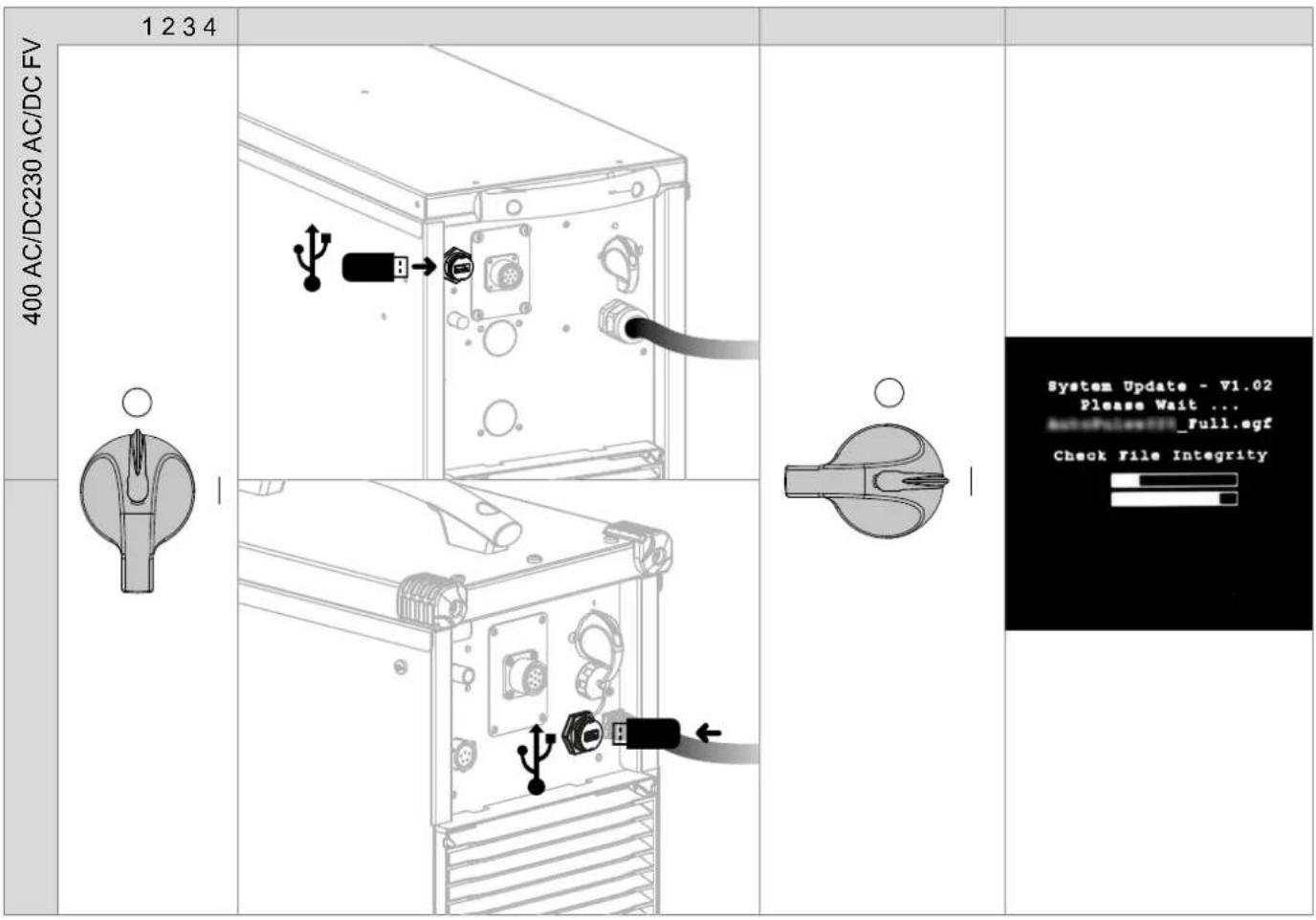
Avant la premiere utilise de votre apparéil, merci de vérifier la présence de nouvelles mises à jour.
Before using your device for the first time, please check for new updates.
Vor der ersten Anwendung des Gerätesitte prufen Sie,ob neue Softwareaktualisierungen verfugbar sind.
13 Antes del primer uso de su aparato, compruebe la presencia de新品asactualizaciones.
TpeTeKAKNcnoJIb3OBAb annapa npoBepbTe HeTo6HOBHeHn npOrpAMMHoro 6ecneueHn.
Voordat u het apparaat voor de eerste keer gebruikt, moet u de aanwezigheid van neue updates controeren.
Prima di utilizzare per la primaolta il vosto appearecchio, vogliate verificare se ci sono nuovi aggiornamenti.
Antes deutilizar o seu dispositorio pela primeira vez,verifique se existem novas atualizacoes.
首次使用设备前,请检查是否存在更新。
初載使用前、デバイスが最新にアツ徴ートをてるか確認てくだい。
Avant la premiere utilisation de vous appeareil, procedez à la calibration des cables de soudage.
Before using the machine for the first time, calibrate the welding cables.
Kalibrieren Sie die Schweizkabel vor der ersten Benutzung Ihres Geräts.
13 Antes de utiliser su aparato por primera vez, calibre los cables de soldadura.
19 Ppeid nepBbIM nCOnb3OBAHnem npoBeaIte KaIb6pOByc BApOuHbIX Ka6eJIe.
Voordat u dit apparaat voor de eerste keer gebruikt要去en de laskabels gekalibreerd worden.
Prima di effettuare il primo utilizzato del vosto apparecchio, procedere alla calibrazione dei cavi di salatura.
Antes deutilizar o seu aparelho pela primarya vez,proceda a calibracao dos cabos de soldadura.
首次使用设备前,请先校准焊接电缆
D. ニーダバイスを最初使用する前に、溶接ケームルを較正てくだき。

1
230 AC/DC FV
400 AC/DC
E
AVERTISSEMENTS - RÉGLES DE SECURITÉ
CONSIGNE GÉNÉRALE
INSTALLATION - FONCTIONNEMENT PRODUIT
INTERFACE HOMME-MACHINE (IHM)

Standard (courant constant)
E-TIG (energie constante)
Wizard Lab
CONDITIONS DE GARANTIE
WARNING - SAFETY REGULATIONS
GENERAL INFORMATION

These instructions must be fully read and understood before operating the machine.
Do not carry out any modifications or maintenance work that is not included in the user manual.
Any personal injury or material damage due to use that does not comply with the instructions in this manual cannot be held at the expense of the manufacturer.
If you have a problem or query, please consult a qualified technician to set up the device correctly.
THE ENVIRONMENT
This equipment should only be used for welding operations within the limits indicated on the rating plate and/or in the user manual. The safety regulations must be observed. In the event of improper or dangerous use, the manufacturer shall not be held liable.
The device must be set up and operated in a location that is free of dust, acids, flammable gases and other corrosive substances. The same applies to the device's storage. Make sure there is sufficient air circulation when in use.
Temperature ranges:
Use between -10 and +40^ (+14 and +104^)
Store between -20 and +55^ (-4 and 131^
Air humidity:
Less than or equal to 50% at 40^ (104^)
Less than or equal to 90% at 20^ (68^)
Altitude:
Up to 1,000 m above sea level (3,280 feet)
PROTECTING YOURSELF AND OTHERS
Arc welding can be dangerous and cause serious injury or death.
Welding exposes people to a dangerous source of heat, light and radiation from the arc as well as electromagnetic fields (caution to those with pacemakers), risk of electrocution, noise and gaseous fumes.
To protect yourself and others, follow these safety instructions:

To protect yourself from burns and radiation, wear insulating, dry, fireproof clothing in good condition without lapels; the clothing must cover the whole body.

Wear gloves that provide electrical and thermal insulation.

Use welding PPE and/or a welding helmet with a sufficient protection level (depending on the application). Protect your eyes during cleaning operations. Wearing contact lenses is strictly forbidden.
It is sometimes necessary to enclose the welding area with fireproof curtains to protect it from arc radiation, spatter and incandescent waste.
Inform people in the welding area not to look at the arc rays or the molten parts and to wear the appropriate clothing to protect themselves.

Wear noise-cancelling headphones if the welding process reaches a noise level above the permissible limit (these must be worn by anyone in the welding area).
Keep hands, hair and clothing away from moving parts (the fan).
Never remove the cooling unit's protective casing when the welding power source is on; the manufacturer cannot be held responsible in the event of an accident.
Newly welded parts are hot and can cause burns when handled. When carrying out maintenance on the torch or electrode holder, make sure that it has sufficiently cooled by waiting at least 10 minutes before starting any work. The cooling unit must be switched on when using a water-cooled torch to make sure that the liquid does not cause burns.
It is important to secure the work area before leaving it, this is to protect people and property.
WELDING FUMES AND GASES

The fumes, gases and dusts emitted by welding are health hazards. Sufficient ventilation must be provided and an air supply may be required. An air-fed mask could be a possible solution if there is inadequate ventilation.
Check that the extraction system is operating effectively by checking it against relevant safety standards.
Caution: welding in confined environments requires remote monitoring for safety reasons. Furthermore, welding certain materials that contain lead, cadmium, zinc, mercury or even beryllium, can be particularly harmful; it is important to thoroughly degrease the parts before welding them.
Gas cylinders must be stored in an open or well-ventilated area. They must be in an upright position and held on a support or on a trolley.
Do not weld near grease or paint.
FIRE AND EXPLOSION RISK

Fully shield the welding area; flammable materials should be kept at least 11 metres away. Fire fighting equipment must be nearby during welding operations.
Beware of hot material or sparks being projected, even through cracks; they can cause a fire or explosion.
Keep people, flammable objects and pressurised containers at a safe distance.
Welding in closed containers or tubes should be avoided and if they are open they should be emptied of any flammable or explosive material (oils, fuels and gas residues, etc.).
Grinding operations must not be directed towards the welding power source or towards any flammable materials.
GAS CYLINDERS
The gas coming out of the gas cylinders can cause suffocation if it becomes concentrated in the welding area (ventilate well). Transportation must be done carefully and safely: gas cylinders must be shut off and the welding power source must be switched off. They must be stored vertically and supported to limit the risk of falling.
Close the gas cylinder between uses. Beware of temperature variations and sun exposure.
The gas cylinder must not come into contact with flames, electric arcs, torches, earth clamps or any other heat or incandescent sources.
Be sure to keep it away from electrical and welding circuits and, therefore, never weld a pressurised cylinder.
Be careful when opening the gas cylinder's valve, keep your head away from the valve and make sure that the gas used is suitable for the welding process.
ELECTRICAL SAFETY

The electrical power supply must be earthed. Use the fuse size recommended on the information panel. Electric shocks can cause serious direct or indirect accidents and even death.
Never touch live parts inside or outside the live power source (torches, clamps, cables and electrodes) as these parts are directly connected to the welding circuit.
Before opening the welding current source, it must be disconnected from the mains and wait 2 minutes. so that all the capacitors are discharged. Do not touch the torch or electrode holder and the earth clamp at the same time.
Make sure to have the cables and torches replaced by a qualified and authorised technician if they become damaged. Select the cable's cross-section size according to the intended application. Always wear dry, undamaged clothing to insulate yourself from the welding circuit. Wear insulated footwear in all work environments.
THE EQUIPMENT'S EMC CLASSIFICATION

This Class A equipment is not suitable for use in a residential setting where power is supplied from the public, low voltage, supply network. There may be difficulties in ensuring electromagnetic compatibility at these sites, this is due to both conducted and radiated radio frequency interference.
TITANIUM 230 AC/DC FV: Provided that the public, low-voltage, supply-network impedance at the point of common coupling is less than Z_max = 0.173 . Ohms, this equipment complies with standard IEC 61000-3-11 and can be connected to public, low-voltage supply networks. The installer or user of the equipment is responsible for ensuring that the network impedance complies with the impedance restrictions, this may involve consulting with the distribution network operator if necessary.
TITANIUM 400 AC/DC:
This material complies with IEC 61000-3-11.
TITANIUM 230 AC/DC FV:
This material complies with IEC 61000-3-12.
TITANIUM 400 AC/DC: This equipment does not comply with IEC 61000-3-12 and is intended to be connected to private, low-voltage networks that are connected to the public supply network only at medium- and high-voltage levels. If connected to a public, low voltage supply network, it is the installer's or user's responsibility to ensure that the equipment can be connected to the power supply by consulting with the distribution network operator.
ELECTRO-MAGNETIC EMISSIONS
An electric current passing through any conductor produces localised electric and magnetic fields (EMF). The welding current produces an electromagnetic field around the welding circuit and the welding equipment.
Electromagnetic fields (EMF) can interfere with some medical implants, such as pacemakers. Protective measures must be taken for people with medical implants. For example, restricted access for passers-by or an individual risk assessment for welding professionals.
All welders must carry out the following procedures to minimise exposure to electromagnetic fields from the welding circuit:
- position the welding cables together and secure them with a clamp, if possible
- position yourself (head and torso) as far away from the welding circuit as possible
- never wrap the welding cables around your body
- do not position your body between the welding cables - keep both welding cables on the same side of your body
- connect the return cable to the workpiece as close as possible to the area to be welded
- do not work next to, sit on or lean against the welding power source
- do not weld when transporting the welding power source or the wire-feed reel

Those with pacemakers should consult a physician before using this equipment.
Exposure to electromagnetic fields during the welding process may have other health effects that are not yet known.
RECOMMENDATIONS FOR EVALUATING THE WELDING AREA AND SET UP
General Information
The user is responsible for setting up and using the arc-welding equipment according to the manufacturer's instructions. If electromagnetic interference is detected, it is the arc-welding equipment user's responsibility to resolve the situation with the manufacturer's technical assistance. In some cases, this corrective action may be as simple as earthing the welding circuit. In other cases, an electromagnetic shield may need to be constructed around the welding power source as well as the entire workpiece with input filters installed. In all instances, electromagnetic interference should be reduced until it is no longer a concern.
Assessing the Welding Area
Before setting up arc-welding equipment, the user must assess the potential electromagnetic issues in the surrounding area. The following should be taken into account:
(a) the presence of other power, control, signal and telephone cables either above, below or next to the arc-welding equipment
(b) radio and television receivers and transmitters
(c) computers and other control equipment
(d) safety-critical equipment, such as industrial equipment safeguarding
(e) the health of people nearby, for example, those with pacemakers or hearing aids
(f) the calibration or measurement equipment used
(g) the immunity of other equipment located nearby
The user must verify that the other equipment used in the surrounding environment is compatible. This may require additional protective measures:
(h) the time of day when welding or other activities are to be carried out
The size of the surrounding area to be taken into account depends on the structure of the building and other activities taking place there. The surrounding area may extend beyond the facility's boundaries.
Assessing the Welding Equipment
In addition to assessing the surrounding area, the arc-welding equipment can also be assessed to identify and resolve instances of disturbance. The emissions assessment should include in situ readings as specified in Article 10 of CISPR 11. In situ readings can also be used to confirm whether the mitigation measures are effective.
RECOMMENDATIONS ON METHODS FOR REDUCING ELECTROMAGNETIC EMISSIONS
a. Public power supply network: Arc-welding equipment should be connected to the public power supply following the manufacturer's recommendations. If interference occurs, it may be necessary to take additional preventive measures such as filtering the public power supply. Consider shielding the power cable within a metal conduit or equivalent for permanently set up arc-welding equipment. The shielding must be electrically continuous along its entire length. The shielding should be connected to the welding power source to ensure good electrical contact between the conduit and the welding power source's casing.
b. Maintaining arc-welding equipment: Arc-welding equipment must undergo routine maintenance according to the manufacturer's recommendations. All accesses, service doors and covers should be closed and properly locked when the arc-welding equipment is in use. The arc-welding equipment must not be modified in any way, except for those modifications and adjustments specified in the manufacturer's instructions. In particular, the arc ignition and stabiliser's spark gap must be adjusted and maintained according to the manufacturer's recommendations.
c. Welding cables: The welding cables should be as short as possible and placed close together near or on the ground.
d. Equipotential bonding: Consider linking together all metal objects in the surrounding area. However, metal objects connected to the workpiece will increase the risk of electric shocks to the user if they touch both the metal objects and the electrode. Therefore, the operator must be isolated from such metal objects.
e. Earthing the workpiece: Where the part to be welded is not earthed for electrical safety reasons or because of its size and location, e.g. a ship's hulls or a building's structural steel framework, an earthed connection can, in some cases but not always, reduce emissions. Care should be taken to avoid earthing parts which could increase the risk of injury to users or damage to other electrical equipment. If necessary, the workpiece's earth connection should be made directly. However, in certain countries where this direct connection is prohibited, the connection should be made with a suitable capacitor chosen in accordance with national regulations.
f. Protective and shielding measures: Selectively protecting and shielding other cables and equipment in the surrounding area can limit interference issues. Protecting the entire welding area could be an option for special applications.
TRANSPORTING AND MOVING THE WELDING MACHINE

The welding power source is equipped with a top handle allowing it to be carried by hand. Be careful not to underestimate the weight of the machine. The handle is not intended as a means of hoisting or suspending the machine.
Do not use the cables or torch to move the welding current source. It must be moved in an upright position.
Do not carry the welding machine over people or objects.
Never lift a gas cylinder and the welding current source at the same time. They have different transportation requirements.
SETTING UP THE EQUIPMENT
- Place the welding power source on a floor with a maximum inclination of 10^ .
- Provide a sufficient area to properly ventilate the source of the welding current and access the machine's controls.
- Do not use in an environment with conductive metal dust.
- The welding power source must be protected from heavy rain and out of direct sunlight.
- The equipment has an IP23 protection rating, meaning:
- it is protected against dangerous access by solid bodies with a diameter >12.5 ~mm
- it is protected against rain falling at 60^ to the vertical
This equipment is, therefore, suitable for outdoor use in accordance with its IP23 protection rating.
Power, extension and welding cables must be fully unwound to avoid overheating.

The manufacturer assumes no responsibility for damage to persons and objects caused by improper or dangerous use of this equipment.
MAINTENANCE/ADVICE


- Maintenance should only be carried out by a qualified technician. Annual maintenance is recommended.
-
Switch off the power supply by disconnecting the plug and waiting for two minutes before carrying out work on the equipment. Inside, the voltages and intensities are high and dangerous.
-
Regularly remove the cover and blow out the dust. Take the opportunity to have the electrical connections checked by a qualified technician using an insulated tool.
- Check the power cable's condition regularly. If the power cable is damaged, it must be replaced by the manufacturer, their after-sales service department or a similarly qualified technician to avoid hazards.
- Leave the welding power source's vents free to allow air to enter and exit the machine.
- Do not use this welding power source for thawing pipes, recharging batteries/accumulators or starting motors.
SETUP - OPERATING THE PRODUCT
Only experienced persons, authorised by the manufacturer, may set up the device. During setup, ensure that the power source is disconnected from the mains system. Serial or parallel power source connections are not allowed. It is recommended to use the welding cables supplied with the unit in order to achieve the product's optimum settings' configuration.
DESCRIPTION
This equipment is a power source for TIG welding with a direct current (DC TIG) or an alternating current (AC TIG) as well as for coated-electrode welding (MMA).
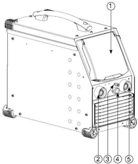
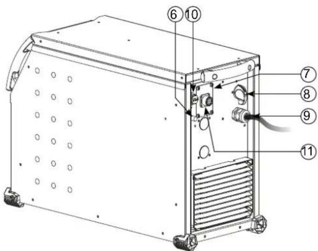
EQUIPMENT DESCRIPTION (I)
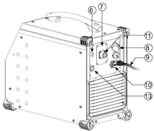
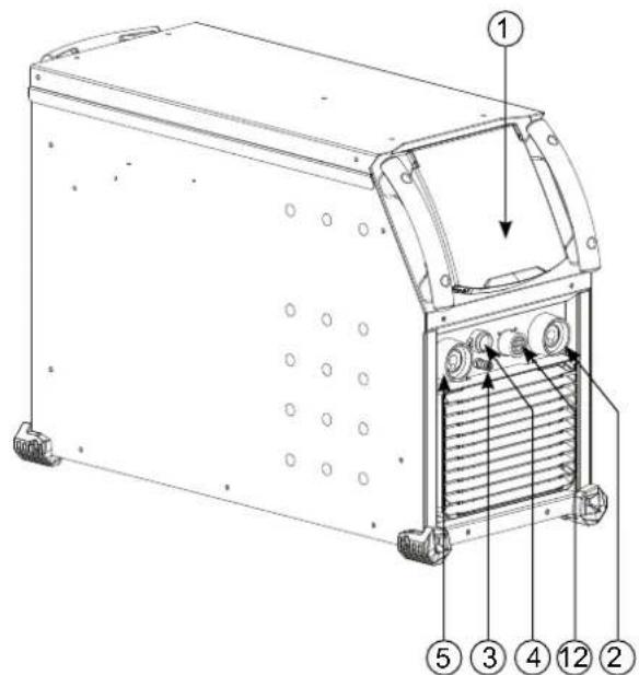
1) Human Machine Interface (HMI) 7
Digital TIG-1 kit connection (optional extra, P.N. 037960)
NUM-1 kit connection (option ref. 063938) = 230 AC/DC FV only
2) Positive polarity socket 8) ON/OFF Switch
3) Torch gas connection 9) Power supply cable
4) Torch button connection 10) USB connection
5) Negative polarity socket 11) Analogue connection
6) Cylinder gas connection 12) Reel or remote HMI connection = 400 AC/DC only
13 Power supply connection and cooling unit management connection
HUMAN-MACHINE INTERFACE (HMI)

Please read the Human Machine Interface (HMI) user manual which forms part of the complete hardware documentation.
HMI
POWER SUPPLY-START-UP
TITANIUM 230 AC/DC FV:
This equipment is delivered with a single-phase, three-pin (E/N/L), 230 V/16 A, CEE17 socket. It comes equipped with «Flexible Voltage» technology and can be supplied from an earthed electrical installation between 110 - 240 V (50 - 60 Hz).
TITANIUM 400 AC/DC:
This equipment is fitted with a 32 A, EN 60309-1 socket and should only be used on a three-phase, 400V (50 - 60 Hz), four-wire electrical network with an earthed neutral pin.
The effective absorbed current (11eff) for the ideal operating conditions is indicated on the equipment. Check that the power supply and its safeguards (the fuse and/or circuit breaker) are compatible with the required current. It may be necessary to change the plug in some countries to allow the product to operate at its optimum conditions.
- The welding current source will go into a protective mode if the supply voltage goes below or above 15% of the specified voltage(s) (a fault code will appear on the display).
- Switching the device on is done by turning the ON/OFF switch (1-8) to the I position; conversely, switching it off is done by turning it to the 0 position. Warning! Never turn off the power supply when the machine is charging.
Fan performance: This equipment is fitted with an intelligent ventilation management system to minimise the machine's noise level. The fans will adapt their speed to match the device's current application and the ambient temperature. The fan will run continuously in MMA mode. In TIG mode, the fan will only run during the welding phase and then stop after cooling. - Warning: increasing the length of the torch or return cables beyond the maximum length specified by the manufacturer will increase the risk of electric shock.
- Arc ignition and arc stabilising are both designed for manual and mechanically guided operations.
CONNECTING TO THE POWER SOURCE
This equipment can be operated using battery-based power sources provided that the auxiliary power meets the following requirements:
-
The voltage must be alternating, set as specified and with a peak voltage of less than 700V for the TITANIUM 400 AC/DC and 400V for the TITANIUM 230 AC/DC FV
-
The frequency must be between 50 - 60 Hz
Checking these conditions is crucial as many power sources produce high voltage spikes that can damage equipment.
USING ELECTRICAL EXTENSION CABLES
All extension cables must be of an appropriate length and cross-section for the equipment's voltage. Use an extension cable that complies with national regulations.
| Input voltage | Length - Extension cable cross-section | ||
| < 45 m > 45 m | |||
| TITANIUM 400 AC/DC 400 V | 6 mm² | ||
| TITANIUM 230 AC/DV FV | 110 V 2.5 mm² 4 mm² | ||
| 230 V 2.5 mm² | |||
GAS CONNECTION
This equipment is equipped with two couplings. A cylinder coupling for putting gas into the device and a torch gas coupling for releasing gas from the end of the torch. We recommend that you use the adaptors supplied with the welding machine to ensure optimum connections.
ACTIVATING THE VRD FEATURE (VOLTAGE REDUCTION DEVICE)
The voltage reducing device (or VRD) is only available for the TITANIUM 230 AC/DC.
This device protects the welder. The welding current is delivered only when the electrode makes contact with the workpiece (low resistance). The VRD function lowers the voltage as soon as the electrode is removed.
The voltage reduction device is deactivated by default. In order to activate it, the user must first open the product and complete the following procedure:
1.) DISCONNECT THE PRODUCT FROM THE POWER SUPPLY and wait for five minutes to ensure that it is safe.
2.) Remove the power source's side panel (see page 89).
3.)Locate the control board and VRD switch (see page 89).
4.) Turn the switch to the ON position.
5.) The VRD function is now activated.
6.) Replace the power source's side panel.
7.) The VRD icon on the device's user interface (HMI) will now be lit up.
To deactivate the VRD function, simply switch the switch back to the OFF position.
RECOMMENDED COMBINATIONS
| DC TIG | (mm) | Amps (A) Electrode | Ø (mm) Nozzle Ø (mm) Argo | Flow Rate (L/min) | |
| 0.3 - 3 | 3 - 75 | 1 | 6.5 | 6 - 7 | |
| 2.4 - 6 | 60 - 150 | 1.6 | 8 | 6 - 7 | |
| 4 - 8 | 100 - 200 | 2 | 9.5 | 7 - 8 | |
| 6.8 - 8.8 | 170 - 250 | 2.4 | 11 | 8 - 9 | |
| 9 - 12 | 225 - 300 | 3.2 | 12.5 | 9 - 10 | |
| ACTIG | 0.5 - 1.5 5 - 50 1 | 6.5 6 - 7 | |||
| 1.5 - 2 50 - 80 1 | 1.6 8 6 - 7 | ||||
| 2 - 3 80 - 110 2 | 9.5 7 - 8 | ||||
| 3 - 4 110 - 150 | 2.4 11 8 - 10 | ||||
| 4 - 5 150 - 180 | 3.2 12.5 | 10 - 12 | |||
| 5 - 6 180 - 240 | 4 | 16 | 12 - 16 | ||
| 6 - 10 | 240 - 400 4.8 19 | 15 - 18 |
TIG WELDING MODE (GTAW)
CONNECTIONS AND ADVICE
TIG welding requires gas shielding (argon).
- Connect the earth clamp to the positive (+) connector. Connect the torch's power cable to the negative (-) connection as well as to the torch and gas button(s) connections.
Make sure that the torch is well fitted and that the consumables (vice grip, collar support, diffuser and nozzle) are not worn out.
- The choice of electrode depends on the TIG welding current.
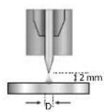
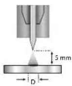
SHARPENING THE ELECTRODE
For optimum performance, it is recommended to use an electrode sharpened in the following way:
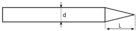
L = 3× d for a low current
L = d for a strong current
PROCESS SETTINGS
| Welding processes | ||||||
| Parameter settings | Settings | Synergy | DC | AC | Wizard | |
| - | Standard | - | ✓ | ✓ | - | Smooth current |
| Pulsed | - | ✓ | ✓ | - | Pulsed current | |
| Fast Pulse | ✓ | - | - | Inaudible pulsed current | ||
| Spot welding | - | ✓ | ✓ | - | Smooth tack welding | |
| Tack welding | - | ✓ | - | - | Pulsed tack welding | |
| Multi-Spot | ✓ | ✓ | - | Repeated smooth spot welding | ||
| Multi-Tack | ✓ | - | - | Repeated pulsed tack welding | ||
| AC Mix | - | ✓ | AC/DC current mixing | |||
| Material type | Fe, Al, etc. | ✓ | - | - | - | Choosing the material to be welded |
| Tungsten electrode diameter | 1 - 4 mm | ✓ | ✓ | ✓ | ✓ | Choosing the electrode's diameter Allows HF ignition currents and synergies to be refined. |
| Ignition type | Lift, HF and Touch. HF | ✓ | ✓ | ✓ | ✓ | Choosing the ignition type |
| Trigger mode | 2T, 4T and 4T LOG | ✓ | ✓ | ✓ | 2T, 4T | Choosing the trigger welding management mode |
| E-TIG | OFF - ON | ✓ | ✓ | ✓ | - | Constant energy welding mode with arc length correction |
| Energy | Hold Thermal coefficient | - | ✓ | ✓ | ✓ | See «Energy» chapter on the following pages. |
| Parameter settings (advanced) | ✓ | ✓ | ✓ | ✓ | HF ignition adjustment | |
Accessing certain welding parameters is dependent on the selected display mode: Settings/Display mode: Easy, Expert or Advanced. Refer to the HMI manual.
WELDING PROCESSES
- Synergy TIG
No longer based on the chosen DC current or the welding cycle's parameter settings but, instead, incorporates welding rules/synergies based on experience. As a result, this mode restricts the number of settings to three basic ones: Material type, welding thickness and welding position.
TIG DC
Suitable for welding ferrous metals such as steel and stainless steel as well as copper, its alloys and titanium.
AC TIG
Suitable for welding aluminium, its alloys and copper.
TIG Wizard
Wizard Lab:
see «Wizard Lab» chapter on the subsequent pages.
Aluminum Wizard, Stainless Steel Wizard, Steel Wizard, Copper Wizard:
This mode is used for pre-assembling or welding parts made of light alloys (AlSi, AlMg and Al99), stainless steel (CrNi), steel (Fe) and copper (CuZn and Cu). The relevant settings, in the form of pre-installed synergies, are the thickness of the parts to be welded and the joint type (butt welding (BW), fillet weld (FW), interior angle (BP), exterior angle or fusing wires together when butt welding. To switch from one mode to the other, press button n°4 on the keyboard (see HMI user manual).
SETTINGS - DC TIG
Standard
This welding method enables high-quality welding on most ferrous materials such as steel, stainless steel, copper, its alloys and titanium. The various current and gas management options offer the user perfect control of the welding operation, from the very start of the welding process to the final cooling of the weld bead.
Pulsed
This pulsed current welding mode combines strong current pulses (I, welding pulse) with weak current pulses (I_Cold, cooling pulse). This pulsed mode allows parts to be assembled whilst limiting both the temperature rise and amount of distortion. Also ideal for in-position welding.
Example:
The welding current (I) is set to 100 A and % (I_Cold) is set to 50%, i.e. cold current = 50% x 100 A = 50 A.
F(Hz) is set to 10Hz , the frequency of the pulse will be 1 / 10Hz = 100ms ; this means that every 100ms , there will be a pulse at 100A , then another at 50A will follow.
- FastPulse
This very high-frequency, pulsed-current welding mode combines high current pulses (I, welding pulse) with low current pulses (I_Cold, workpiece cooling pulse). FastPulse mode maintains the arc when using the high-frequency pulsed welding mode, however, it operates at frequencies that are less unpleasant, or even inaudible, to the welder.
- Spot welding
This spot welding mode allows parts to be pre-assembled before welding. Spot welding can be controlled manually using the trigger or by a predefined time delay. This spot welding time makes it easier to reproduce and produce non-oxidised spot welds.
Multi-Spot
This is a spot welding mode similar to SPOT TIG but with defined spot welding and stopping times as long as the trigger is held down.
- Tack welding
The machine's tack welding mode can also be used to pre-assemble parts before welding but this time in two phases: the first phase of pulsed DC welding concentrates the arc for better penetration; this is followed by a second phase of standard DC welding, which widens the arc and therefore the weld pool to ensure the tack weld.
The times of the two tack welding phases are adjustable which makes it easier to reproduce and carry out non-oxidised tack welds.
Multi-Tack
It is a pointing mode similar to TIG Tack, but with a sequence of pointing times and stop times defined as long as the trigger is pressed.
SETTINGS-AC TIG
Standard
This welding mode is dedicated to welding aluminium and its alloys (Al, AlSi, AlMg and AlMn). The alternating current allows the aluminium to be stripped clean, which is essential for welding properly.
Balance (%T_AC):
During the positive wave, any oxidation is removed. During the negative wave, the electrode cools down and the parts are welded together, this is called penetration.
By changing the ratio between the two alternations via the balance setting, either cleaning is favoured or penetration (the default setting is 30% ).
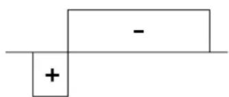
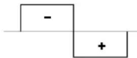
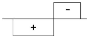
20%: Max. penetration 50% 60%: Max. cleaning
Pulsed
This pulsed current welding mode combines strong current pulses (I, welding pulse) with weak current pulses (I_Cold, cooling pulse). This pulsed mode allows parts to be assembled whilst limiting both the temperature rise and amount of distortion. Also ideal for in-position welding.
Example:
The welding current (I) is set to 100 A and % (I_Cold) is set to 50%, i.e. cold current = 50% x 100 A = 50 A.
F (Hz) is set to 10Hz , the frequency of the pulse will be 1 / 10Hz = 100ms ; this means that every 100ms , there will be a pulse at 100A , then another at 50A will follow.
- SPOT WELDING
This spot welding mode allows parts to be pre-assembled before welding. Spot welding can be controlled manually using the trigger or by a predefined time delay. This spot welding time makes it easier to reproduce and produce non-oxidised spot welds.
Multi-Spot
This is a spot welding mode similar to SPOT TIG but with defined spot welding and stopping times as long as the trigger is held down.
- AC Mixed
This AC welding method is used to weld aluminium and its thick alloys. It mixes DC sequences during AC welding processes which increases the energy delivered to the workpiece. The ultimate goal is to accelerate the work flow rate and, therefore, subsequent productivity when assembling aluminium. This mode cleans the workpiece less, so it is important to work on clean sheet metal.
E-TIG
This mode allows welding with a constant power supply by measuring the arc length variations in real time to ensure a weld bead with consistent width and penetration. In cases where the assembly process requires the welding energy to be controlled, E-TIG mode guarantees that the welder will respect the welding power regardless of the torch's position in relation to the workpiece.
Standard (constant current)
E-TIG (constant energy)
Wizard Lab
This welding mode allows complex (non-standard) welding cycles to be carried out with a series of steps. Each step is characterised by a current ramp, a step and a particular current type (DC, AC or pulsed).
Wizard Lab is configured in three stages:
- welding cycle sequence (number of steps, repetition loops, etc.)
- each step's parameter settings (ramp and current type, etc.)
- specific, advanced parameter settings
STEP: each step can be customised by changing the current type (DC or AC), the current form (standard or pulsed) as well as the ramp up to the set welding current (see «Setting a STEP» section). Each step can be fully customised.
Welding cycle: a welding cycle consists of a Pre-Gas stage, one or more welding steps (see «Welding Cycle Definition» section) and a Post-Gas stage.
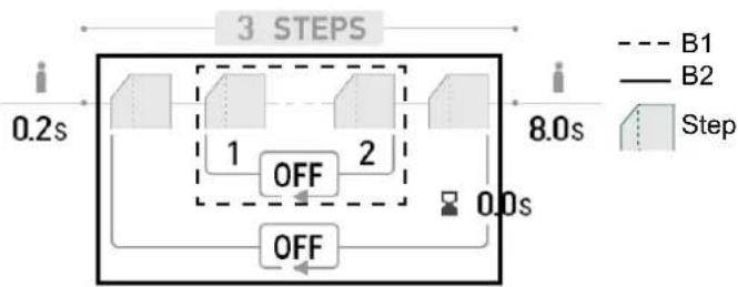
Loops: there are two different loops (see «Definition of the welding cycle» section):
- The welding cycle's inner loop (B1). Within the cycle, the user can choose to make one or more loops (repeating two or more of the welding
steps); the user can even carry out infinite loops depending on the application, for example, AC MIX welding, which repeats two DC and AC steps. - Cycle loops (B2). The user can choose to repeat the cycle (excluding the Pre-Gas and Post-Gas phases) once or several times (or even infinitely).
They can also adjust the delay period between two repeated welding steps if necessary (e.g. MULTITACK welding, which repeats the TACK welding cycle with a delay period between two points as long as the trigger is held down).
Defining the welding cycle:
| Unit | ||
| Number of steps - The number of steps defines the welding cycle | ||
| Pre-Gas s Time for purging the torch and establishing the gas shielding before ignition | ||
| Number of loop steps - Repeat loops in the welding cycle (B1) | ||
| Input step - The repeat loop's starting step in the cycle (B1) | ||
| Output step - The repeat loop's ending step in the cycle (B1) | ||
| Number of loops of the cycle | - Repeat loops in the entire welding cycle (B2) | |
| Inter-loop time s The time between two repetitions of the whole welding cycle (B2) | ||
| Post Gas | s | Gas shielding duration after extinguishing the arc. It protects the part and the electrode against oxidation. |
Setting up a STEP:
| Unit | ||
| STEP 1/x Selecting a STEP to be configured. | ||
| MODE | DC-DC+AC | Selecting the step welding current type |
| PULSED | OFFON | Pulses the set current |
| AC waveform - Waveform in AC. | ||
| Welding frequency Hz Polarity reversal welding frequency- cleaning | ||
| Cleaning percentage % | Welding time dedicated to cleaning (%) | |
| Current surge | s | Transition ramp between the previous step and the active step's current levels |
| Welding current | A | Welding current |
| Waveform | - Pulsed part waveform | |
| Cooling current | % | Second «cooling» welding current |
| Cooling time | % | The pulse's hot current (I) time balance |
| Pulse frequency | Hz Pulse frequency | |
| The step's time duration | min. | Step or trigger mode* welding-current duration |

*In 2T mode, the step duration settings control allows the user to control for how long the configured step will go on when the trigger is released; the cycle will end between the chosen exiting step and the last one.

*The step time setting allows the user to switch from step-to-step by pressing and releasing button 2 in 4T mode or with a two-button torch.
Advanced settings, only available in «Advanced» display mode:
| Advanced settings | Settings | Description |
| HF level | 1 - 10 Index | setting the voltage from 5 - 14 kV |
| HF duration | 0.01 - 3 s | HF time before stopping |
| Breakdown voltage | OFF, 0 - 50 V | Higher arc voltage before stopping the welding machine |
| Time to breakdown | 0 - 10 s | Duration of breakdown voltage |
| Bonding voltage | OFF, 0 - 50 V | Lower arc voltage before stopping the welding power source (Anti-Stick) |
| Delay before bonding | 0 - 10 s | Duration of breakdown voltage |
CHOOSING THE ELECTRODE'S DIAMETER
| Electrode Φ (mm) | DC TIG | AC TIG | ||
| Pure tungsten | Tungsten with oxides | Pure tungsten | Tungsten with oxides | |
| 1 | 10 > 75 | 10 > 75 | 15 > 55 A | 10 > 70 A |
| 1.6 | 60 > 150 | 60 > 150 | 45 > 90 A | 60 > 125 A |
| 2 | 75 > 180 | 100 > 200 | 65 > 125 A | 85 > 160 A |
| 2.5 | 130 > 230 | 170 > 250 | 80 > 140 A | 120 > 210 A |
| 3.2 160 > 310 | 225 > 330 150 > 190 A 150 > | 250 A | ||
| 4 275 > 450 | 350 > 480 180 > 260 A 240 > | 350 A | ||
| Approximately = 80 A per Ø mm Approximately = 60 A per Ø mm | ||||
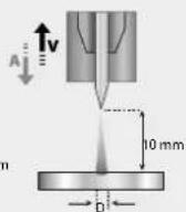
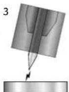
CHOOSING THE IGNITION TYPE
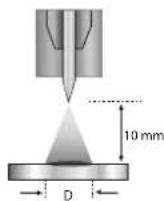
Lift: Arc-Lift ignition (for HF-sensitive environments).
HF: non-contact, high-frequency ignition system for tungsten electrodes
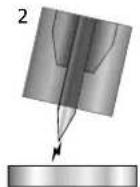
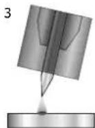
Touch HF: Delayed, high-frequency ignition after the tungsten electrode has made contact with the workpiece.
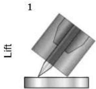
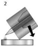
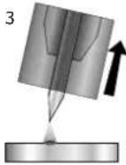
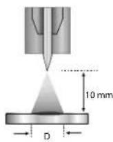
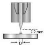
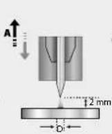
1.) Position the torch's nozzle and the electrode tip on the workpiece and activate the torch's button.
2- Tilt the torch until a gap of about 2 - 3 mm separates the electrode's tip from the workpiece. The arc will start.
3.) Return the torch to its normal position to start the welding cycle.
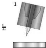
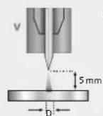
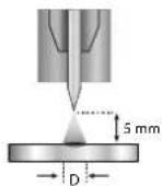
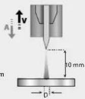
1.) Place the torch in the welding position above the workpiece (with a distance of about 2 - 3 mm between the electrode's tip and the workpiece).
2.) Press the torch's button (the arc will ignite without contact using high voltage [HF] ignition pulses).
3.) The initial welding current circulates, the welding continues according to the welding cycle.
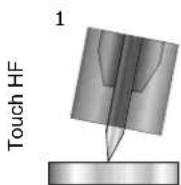
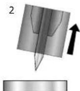
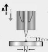
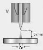
1.) Position the electrode's tip on the workpiece and press the torch button.
2.) Lift the electrode from the workpiece.
3.) After a delay of 0.2s , the arc will ignite without contact using high voltage (HF) ignition pulses; the initial welding current will flow and the welding will continue according to the welding cycle.
Advanced settings, only available in «Advanced» display mode:
| Advanced settings Settings Description |
| HF duration 0.01 - 3 s HF time before stopping |
| HF level 0 - 10 Index setting the voltage from 5 - 14 kV |
COMPATIBLE TORCHES AND TRIGGER ACTIONS
| Single trigger | Double button | Double button & potentiometer | Up & down |
| √ | DB | √ | UP Down |
For the one-button torch, the button is called the «main button».
On the two-button torch, the first button is called the «main button» and the second is called the «secondary button».
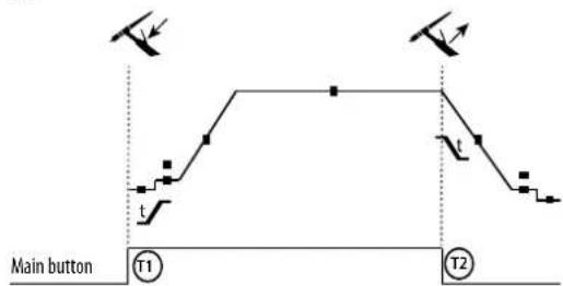
·2T
T1 - The main button is pressed, the welding cycle starts (Pre Gas, I_Start, UpSlope and welding).
T2 - The main button is released, the welding cycle is stopped (DownSlope, I Stop, Post Gas).
When the double-button torch is in 2T mode, the secondary button is operated in the same way as the main button.
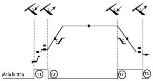
4T
-4TLOG
T1 - The main button is pressed, the cycle starts from the Pre Gas and stops in the I_Start phase.
T2 - The main button is released, the cycle continues to UpSlope and welding processes.
T3 - The main button is pressed, the cycle goes into DownSlope and stops in the I_Stop phase.
T4 - The main button is released, the cycle ends with Post Gas. NB: for torches, double-button torches and double-button torches with a potentiometer
«high/welding current» button and active potentiometer, «low» button inactive.
T1 - The main button is pressed, the cycle starts from the Pre Gas and stops in the Start phase.
T2 - The main button is released, the cycle continues in UpSlope and welding.
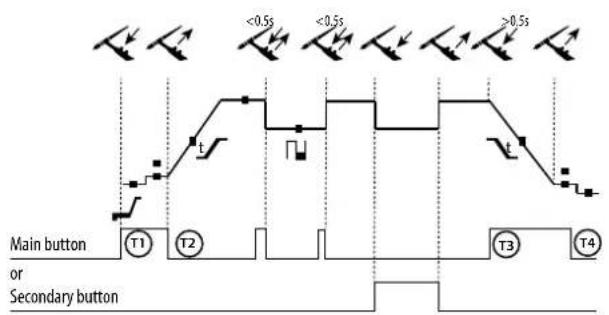
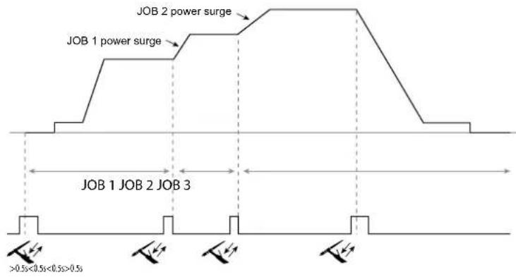
LOG: This operating mode is used in the welding phase:
-
A brief push of the main button (< 0.5 s) switches the current from I_Welding to I_Cold and vice versa.
-
When the secondary button is held down, the current switches from I_Welding to I_Cold.
-
When the secondary button is held down, the current switches from I Cold to I Welding.
T3 - Holding down the main button (> 0.5 s) makes the cycle go into DownSlope and then stop in the I_Stop phase.
T4 - The main button is released, the cycle ends with Post Gas.
For double-button or double trigger torches with a potentiometer, the «upper» trigger carried out the same function as the single-trigger torch. The «lower» trigger switches the machine to a cold current when it is held down. The torch's potentiometer, when present, allows the usedr to adjust the welding current from 50 - 100% of the displayed value. The «Up & Down» feature allows the current to be adjusted at the torch.
TRIGGER-CONTROL CONNECTION
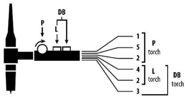
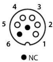
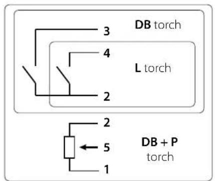
SRL18 torch wiring diagram Electrical diagram according to the type of torch
| Torch types Wire type | Associated connector pin | |||
| Double-button torche with potentiometer | Double-button torch Trigger | torch | Common/Mass Two | |
| Button 1 | Four | |||
| Button 2 | Three | |||
| Potentiometer com-mon/ground | Two | |||
| 10 V | One | |||
| Cursor | Five | |||
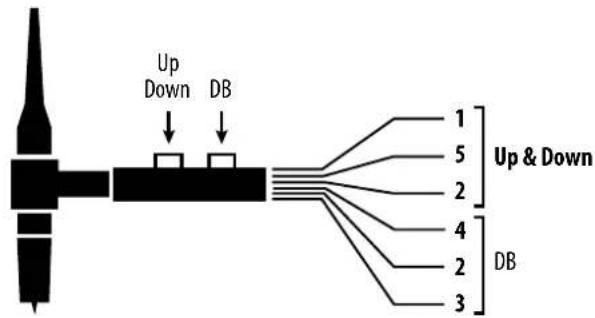
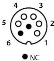
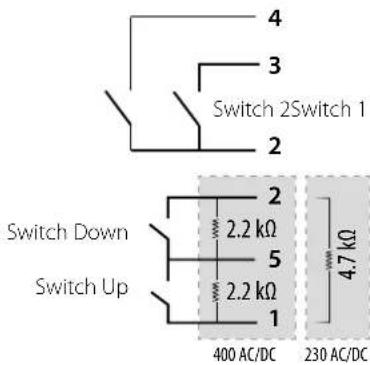
Up & Down torch wiring diagram Up & Down torch electrical diagram
| Torch type Wire type | Associated connector pin | |
| Up & Down Torch | Common Switch 1 & 2 | 2 |
| Switch 1 4 | ||
| Switch 2 3 | ||
| Common Up & Down Switch | 5 5 | |
| Up Switch 1 | 1 | |
| Down Switch 2 | 2 |
400 AC/DC 230 AC/DC
MANUAL GAS PURGE
Oxygen in the torch can lead to decreased mechanical performance and may result in a decreased corrosion-resistance level. To purge the gas from the torch, press and hold push-button n^1 (see HMI user manual) and follow the on-screen procedure.
CHOOSING THE SETTINGS
Unit
| Pre-Gas s Time for purging the torch and establishing the gas shielding before ignition | ||
| Current (starting) | %/A This start-up current is a warm-up phase before the current ramp-up. | |
| Time (starting) | s Dwell time at start-up before ramping up | |
| Current surge s Allows a gradual increase in welding current | ||
| Welding current | A | Welding current |
| Fade out | s | Avoids cratering at the end of welding process as well as the risk of cracking, particularly in light alloys. |
| Stopping current | %/A | This stopping current is the phase after the current ramp down. |
| Stopping time s Stopping time is a phase after the down ramp in running | ||
| Thickness | mm | Thickness of the workpiece to be welded |
| Position | - | Welding position |
| Post gas | s | Gas shielding duration after extinguishing the arc. It protects the part and the electrode against oxidation when cooling. |
| Waveform | - | Pulsed part waveform |
| AC waveform | - | Alternating current (AC) waveform |
| Cooling current | %/A Second «cooling» welding current | |
| Cooling time | % | The pulse's hot current (I) time balance. |
| Frequency (of pulses) | Hz | Pulse frequency between the welding current and the cold current: PARAMETER SETTING TIPS: • If welding with a manual filler metal, then F (Hz) is synchronised to the filler metal application movement. • If the sheet metal is thin without a filler metal (< 0.8 mm), F (Hz) > 10 Hz. • When welding in position, then F (Hz) < 100 Hz |
| Spot welding s Manual or a defined duration | ||
| Welding time | Manual /s | Welding time |
| Pulse duration s Manual | or time-dependent pulse phase | |
| Non-pulsed duration s Manual or time-dependent smooth current phase | ||
| Welding frequency % Polarity reversal welding frequency- cleaning | ||
| Percentage of cleaning | % Welding time dedicated to cleaning (30-35% by default) | |
| AC Time s Duration of AC TIG welding | ||
| DC Time s Duration of DC TIG welding | ||
| Duration between two points | s | The time between the end of a weld (excluding Post Gas) and the start of a new weld (including Pre Gas). |
Access to some welding parameter settings depends on the welding process used (synergy, AC or DC, etc.) and the selected display mode (Easy, Expert or Advanced). Refer to the HMI manual. Some settings in % or A depend on the display mode selected (Easy, Expert or Advanced).
MMA (SMAW) WELDING MODE
CONNECTIONS AND ADVICE
- Connect the cables, electrode holder and earth clamp to the socket connections.
- Respect the polarities and observe the welding currents indicated on the electrode's box.
- Remove coated electrodes from the electrode holder when the welding power source is not in use.
-
This device is equipped with three Inverter-specific features:
-
Hot Start provides an overcurrent at the beginning of the welding process.
-
Arc Force delivers an overcurrent that prevents the electrode from sticking to the workpiece when the electrode enters the weld pool.
- The Anti-Stick feature means the electrode can be easily detached without allowing it to turn red if it becomes stuck.
PROCESS SETTINGS
| Welding processes | |||||
| Parameter settings | Settings Standard Pulsed AC | ||||
| Electrode type | RutileBasicCellulosic | ✓ | ✓ | ✓ | The type of electrode determines specific parameters depending on the type of electrode used; this is in order to optimise its weldability. |
| Anti-Stick OFF - ON | ✓ | ✓ | ✓ | The Anti-Stick feature is recommended for safely removing an electrode, it prevents it from sticking to the workpiece (the current is automatically cut off). | |
| Polarity | Direct (+++ and -=)Inverted (++- and-=+) | ✓ | ✓ | - | The product's accessories are changed in the event of a direct or reverse polarity change. |
| Energy | HoldThermal coefficient | ✓ | ✓ | ✓ | See «Energy» chapter on the following pages. |
Accessing certain welding parameters is dependent on the selected display mode: Settings/Display mode: Easy, Expert or Advanced. Refer to the HMI manual.
WELDING PROCESSES
Standard
This welding mode is suitable for most applications. It can be used with all types of coated, rutile, basic and cellulosic electrodes and on all materials: steel, stainless steel and cast iron.
Pulsed
This welding mode is suitable for applications in the vertical up position (PF). Pulsing keeps the weld pool cold while promoting material transfer. Without pulsing, vertical up welding requires a «Christmas tree» movement, i.e. a difficult, triangular movement. Thanks to MMA pulsed welding, this movement is no longer necessary; depending on the thickness of your workpiece, a straight up movement may suffice. However, if you wish to enlarge the weld pool, a simple sideways movement, similar to flat welding, is adequate. In this instance, you can set the pulse current frequency on the display screen. This method offers greater control of the vertical welding process.
AC
This welding mode is used in very specific cases where the arc is not stable or straight, when it is subjected to magnetic blow-outs (magnetised parts or nearby magnetic fields, etc.). The alternating current leaves the welding arc unaffected by its electrical environment. It is necessary to check that your coated electrode can be used with an AC current.
CHOOSING COATED ELECTRODES
-
Rutile electrode: very easy to use in all welding positions.
-
Basic electrode: used in all positions, suitable for safety work due to its increased mechanical properties.
Cellulosic electrode: very dynamic arc with a high melting speed, its capacity for use in all positions makes it especially suitable for working on pipelines.
CHOOSING THE SETTINGS
| Unit | ||
| Percentage Hot Start | % | Hot Start is a feature that delivers an overcurrent upon ignition to prevent the electrode from sticking to the workpiece. The voltage (% of welding current) and time (seconds) can both be set. |
| Hot Start duration s | ||
| Welding current A | The welding current is set according to the selected electrode's diameter and type (refer to the electrode's packaging). | |
| Cooling current % Second «cold» welding current. | ||
| Arc Force % | Arc Force is an overcurrent delivered to prevent the electrode or molten metal from sticking it touches the weld pool. | |
| AC waveform % Waveform in AC. A trapezoid (or Christmas tree) motion is recommended. | ||
| Welding frequency Hz Polarity reversal welding frequency + or - | ||
| Pulse frequency | Hz Pulse mode pulse frequency. | |
Accessing certain welding parameters is dependent on the selected display mode: Settings/Display mode: Easy, Expert or Advanced. Refer to the HMI manual.
ADJUSTING THE WELDING CURRENT
The following settings correspond to the available current range depending on the type and diameter of the electrode. These ranges are quite wide as they depend on the application as well as the welding position.
| Electrodeø(mm)Rutile E6013(A)Basic E7018(A)Cellulosic E6010(A) | |||
| 1.6 30 - 60 30 - 55 - | |||
| 2.0 50 - 70 50 - 80 - | |||
| 2.5 | 60 - 100 | 80 - 110 | 60 - 75 |
| 3.15 | 80 - 150 | 90 - 140 | 85 - 90 |
| 4.0 | 100 - 200 | 125 - 210 | 120 - 160 |
| 5 150 -290 | 200 - 260 | 110 - 170 | |
| 6.3 | 200 - 385 | 220 - 340 - | |
ADJUSTING ARC FORCE
It is advisable to set the Arc Force to the middle position (0) when starting to weld and to adjust it according to the welding results and the user's preferences. Note: the Arc Force setting range is determined by the type of electrode selected.
HOT START SETTINGS
It is advisable to set the Hot Start feature low for thin sheet metal and to set it high for thicker and more difficult sheet metal (dirty or oxidised parts).
ENERGY
In addition to the weld bead's energy reading after welding, this mode, developed for welding with DMOS-supported energy control, allows the user to change the following settings:
- The thermal coefficient according to the standard used: 1 for ASME standards and 0.6 (TIG) or 0.8 (MMA) for European standards. The displayed energy is calculated taking into account this coefficient.
- The weld bead's length (OFF - mm): If a length is recorded, then the energy display is no longer in joules, but in joules/mm (the unit in the display «J» will flash).
SAVING AND RECALLING JOBS
Accessible through the «JOB» icon on the main screen.
The active settings are automatically saved and recalled the next time you turn on the machine.
In addition to the active settings, it is possible to save and recall JOB configurations.
There are 500 JOBS for TIG welding processes and 200 for MMA welding processes. Memory storage is based on the current process settings, the active settings and the user profile.
JOB mode
JOB mode allows you to create, save, recall and delete JOBS.
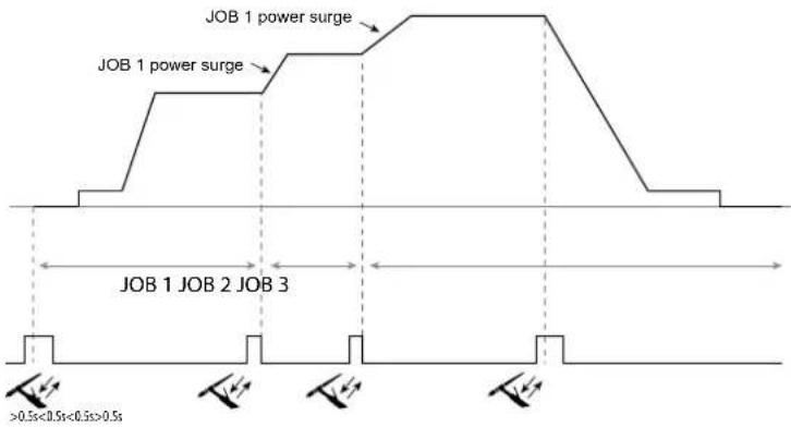
Quick Load - Recall JOBs from the trigger when not welding.
Quick Load is a non-welding JOB recall mode (20 JOBs max.) and is only available for TIG processes.
From a list of previously created JOBs, JOB recalls are done by short trigger presses. All trigger modes and welding modes are supported.
MultiJob - Recall JOBs using the trigger when welding.
From a MultiJOB list made up of previously created JOBs, this linking mode makes it possible to weld up to 20 JOBs in sequence with no interruption.
When the mode is activated, JOB N°1 in the list will be loaded and displayed. The trigger mode is forced to 4T.
During welding, this mode allows the JOBs in the uploaded list to be linked together by carrying out short presses on the torch's buttons.
The welding process is stopped by holding down the torch's buttons or, when the welding cycle is finished, JOB N°1 is reloaded for a future welding sequence.
When the mode is activated, JOB N°1 in the list will be loaded and displayed.
The JOBs recall sequence is looped: when the last JOB on the list is reached, the next one will be JOB N°1.
Activate the welding process by holding down the torch's buttons.
C5
From a previously created C5 list of 5 JOBs, this simple automation mode from the Remote Control connector allows the user to recall JOBs via a PLC (see note on the website - https://planet.gys.fr/pdf/spdoc/fr/CONNECT_5.pdf).
OPTIONAL REMOTE CONTROL
- Analogue remote control RC-HA1 (P.N. RC-HA1):
An analogue remote control can be connected to the power source via the connection (I-11).
This remote control allows the current to be adjusted between 50 - 100% of the set current. In this configuration, all of the power source's modes and features can be accessed and configured.
- Analogue remote control RC-MMA/DEGAUSS (P.N. 066496)
An analogue remote control can be connected to the power source via the connector (1-4).
In MMA only, the control allows the current to be varied from 50% to 100% of the current set via a potentiometer, the welding polarity to be reversed via the polarity switch and the welding current source to be activated or deactivated to protect the welder during handling.
- Remote control RC-MMA/TIG-FA1 pedal (P.N. 045682):
A remote-control pedal can be connected to the power source via the connection (I-11).
The pedal allows you to adjust the current from the minimum to 100% of the set welding current. In TIG mode, the power source will only work in 2T mode. Furthermore, the current's rise and fall are no longer managed by the power source (inactive functions) but by the user using the foot pedal.
- Remote HMI - RC-HD2 digital remote control (P.N. 062122):
400 AC/DC: A digital remote control can be connected to the power source via the connection (I-12).
230 AC/DC FV: A digital remote control can be connected to the power source via the optional NUM-1 kit (I-7).
This remote control is designed for MMA and TIG welding processes. It allows the user to remotely adjust the welding unit. An ON/OFF button is used to switch on or off the digital remote control. When the digital remote control is switched on, the power source's HMI will display the current and voltage values. As soon as the HMI is turned off or disconnected, the welding machin's HMI is reactivated.
Terminals
This product is equipped with a female remote control terminal.
The purposely designed, seven-prong, male connector (optional extra, PN: 045699) allows different types of remote control to be connected. For wiring, follow the diagram below.
| REMOTE CONTROL TYPE Wire type Associated connector pin | |||
| C5 | Foot pedal Manual remote control | 10 V A | |
| Cursor B | |||
| Common / Earth | C | ||
| Switch | D | ||
| AUTO-DETECT | E | ||
| ARC ON | F | ||
| REG I | G | ||
OPTIONAL COOLING UNIT
| Compatibility Part number Name Cooling power Capacity | Power-supply voltage | ||
| TITANIUM 230 AC/DC FV 070820 KOOLWELD 1 | 1,000 W | 3 L 24 V | |
| TITANIUM 400 AC/DC 013537 WCU 1KW C 5.5 L 400 V +/- 1 |
The machine will automatically detect the cooling unit. To deactivate the cooling unit (OFF), please refer to the HMI's user manual.
The following safeguarding measures are supported by the cooling unit to ensure that the torch and user are protected:
- Minimum coolant level
- Minimum coolant flow rate through the torch
Thermally protected coolant
Ensure that the cooling unit is switched off before disconnecting the torch's fluid inlet and outlet hoses.
Coolant is harmful and can irritate the eyes, mucous membranes and skin. Hot liquids can cause burns.
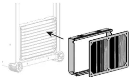
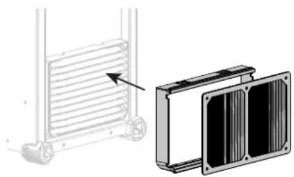
OPTIONAL FILTER KIT
Dust filter (P.N 046580) with fine filtration: 630~ m (0.63 mm).
Please note that using this filter reduces the welding machine's duty cycle.
The dust filter should be cleaned regularly to avoid the risk of overheating due to blocked air vents.
Unclip and clean with compressed air.
ADDING FEATURES
The manufacturer, GYS, offers a wide range of compatible products for your welding equipment.
To discover them, scan the QR code.
WARRANTY CONDITIONS
The warranty covers any defects or manufacturing faults for two years from the date of purchase (parts and labour)
The warranty does not cover:
Any other damage caused by transport
The parts' normal wear and tear (e.g. cables and clamps, etc.).
- Misuse-related incidents (misfeeding, dropping or disassembling the device)
- Environmental failures (pollution, rust and dust, etc.)
Should the appliance malfunction, return it to your distributor together with:
- dated proof of purchase (receipt or invoice, etc.)
- a note explaining the breakdown
WAARSCHUWINGEN - VEILIGHEIDSINSTRUCTIES
ALGEMENE INSTRUCTIES

MMA (SMAW) LASMODULE
AANSLUITING EN ADVIEZEN
KIT FILTER OPTIONEEL
Bilancimiento (%T_AC):
MODALITA DI SALDATURA MMA (SMAW)
COLLEGAMENTO E CONSIGLI
- IHM a distance - commande a distance digitale RC-HD2 (rif. 062122) :
Filiale / Subsidiary
Unit 3
Great Central Way
CV21 3XH - Rugby - Warwickshire
United Kingdom
www.gys-welding.com +44 1926 338 609 uk@gys.fr
GYS GmbH
Tolerance I (courant)
Identification - Options ON
This interface (HMI) manual forms part of the complete documentation. A general manual is included with the product. Read and follow the general manual's instructions, particularly the safety instructions!
Only for use with the following products:
TITANIUM

Version du calculi
This user manual describes the following software versions:
1.86.
The software's version can be found on the main menu: System / Information / MMI
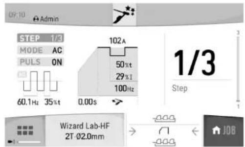
Using the device
The main screen contains all the necessary information for the entire welding process, including the pre-, mid- and post-welding phases (the interface may change slightly depending on the selected process).
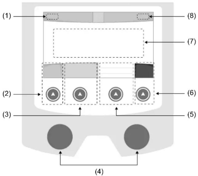
(1)User name/Traceability
(2) Push button n^1 : Main menu or return to the previous menu
(3) Push button n°2 : Current Welding Process Settings
(4) Navigation buttons
(5)Push button n^3 :Settings
(6)Push button n^4 :Job or Validation
(7) Current settings
(8) Current and Power Readings
Main menu
The main menu screen is displayed when the product is first started.
Navigating between the different sections is done using the dials and buttons.
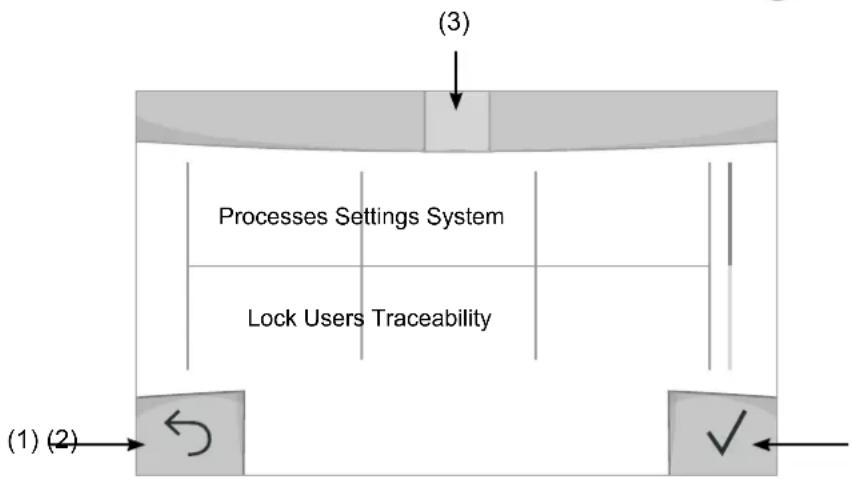
(1) Back
(2) Validation
(3) The current section's computer icon
Processes
Access to some welding processes depends on the product:
TIG (GTAW)
Arc welding with non-stick electrode, in a protective gas atmosphere
MMA(SMAW)
Arc welding with coated electrode
Settings (User settings)
User Level
- Easy: reduced display and functionality (no access to the welding cycle).
- Expert: full display, allows the user to adjust the timing of the different welding cycle phases.
- Advanced: full display, allows the user to adjust all the welding cycle settings.
Language
Choice of the interface language (English, French, German, etc).
Brightness
Adjusts the interface screen's brightness (setting from 1 [very dark] to 10 [very bright]).
User Code
Customise the user's access code to safely lock the machine (default 0000).
Tolerance I (current)
Current tolerance control:
OFF: Freely adjustable, the current setting is not limited.
± 0A : no tolerance, current limitation.
± 1A > ± 50A : The setting range at which the user can adjust their current.
System
Machine name
Information about the device's name and the option to customise it can be reached by pressing on the interface.
Clock
Setting the time, date and format (AM/PM).
Cooling system
- OFF : The cooling unit is switched off.
- ON : The cooling unit is permanently switched on.
- AUTO : automatic control (activated during welding and deactivated 10 minutes after welding has ended)
PURGE : a function designed to purge the cooling unit or to filling beams, during which the safeguards are disabled (see the cooling unit manual to purge your product safely).
Validation
The validation of welding equipment is an operation to check the performance of the product in relation to its settings.
The CALIWELD calibration case (option, ref. 060456) is used to issue a validation report and to verify the welding values.
Press push-button no. 3 ( ) to display the most recent validation date of the item.
You can also indicate the expiration of the validity period in months. When the validation date expires, a prompt appears on the screen to revalidate the product.
Information
Configuration data of the product's system components:
- Model
- Serial number
Device name - Software version

Press push-button no. 3:
Exporting the machine configuration to the USB stick (not supplied)
Productivity
Product usage data :
- Ignition time
Welding time
-etc.
Reset
Resetsthe product settings:
- Partial: defaults the values of the current welding process.
- Total: all the machine's configuration will be reset to the factory settings.
Lock
This machine's interface screen can be locked to protect any work in progress and prevent unintentional or accidental changes. The current settings window can still be modified with the settings chosen in the Settings menu (see previous page). All other functions are inaccessible.
To unlock the interface, press push button #1 and enter your 4-digit user code (default 0000).
Users
The user mode enables the machine to be shared between several users. The first time that the machine is started, it will be in Admin mode. The administrator can create user profiles. Each user has his own setup (mode, setting, process and JOBs etc.) and this cannot be modified by another user. Each user needs a personal four-digit code in order to sign in to the machine.
- The administrator has access to the entire general menu.
- Users have access to a simplified interface. Users do not have the ability to delete information (Tracking, Jobs, User profiles, etc).
User configuration interface (reserved for the administrator).
The left side of the screen lists the users. The administrator has the ability to sort these users by name or by date by quickly pressing button n°2. Pressing this button for a prolonged time will delete the active user(s) instead (although the Admin account cannot be deleted).
On the right side of the screen, you can see the details of all the users previously created with the following information: Avatar, Name, Team No. and Tolerance (%) .
Creating a user profile
Press button n°3 to create a new user.
- User: Customise the user's name by pressing push button n^3
-Avatar:Choice of avatar colour - Team : Assignment of the team number (10 max)
-Usercode:personalaccesscode(default0000) - Current setting tolerance I:
OFF: freely adjustable, the current setting is not limited.
± 0.0A : no tolerance, limiting the current (not recommended).
± 0.A > ± 50A : Setting interval at which the user can vary their current.
Changing a user profile
Select the user on the left side of the screen and press the push button n^4
Selecting users
If one or more user profiles are created, the user block displays all of the machine's users.
Select the user of your choice and press to confirm the choice. You will be asked for an unlock code.
The «Close» feature locks the machine on the user's choice so that no other settings are accessible. This screen remains the same when the machine is switched on (OFF -> ON switch).
User display
The active avatar and username are displayed at the top left of the screen.
Unlocking code
Each user profile is protected by a personal, four-digit code. The default code will be 0000 if not changed. After failing to correctly enter your personal code three times, the interface will be blocked and you will be asked for an unlock code.
This code is made up of six digits and cannot be changed. It is: 314159.
Traceability
This welding management interface allows you to track/record every step of the welding operation, bead by bead, during any industrial operation. This quality-driven approach ensures high post-production welding quality through analysis, evaluation, reporting and documentation of the recorded welding settings. This feature allows for the accurate and fast collection and storage of data required under EN ISO 3834. This data can be recovered and exported to a USB stick.
1- Start - Creating a tracking system
- Personalise the site's name by pressing push button n°3.
- Sampling interval :
- Hold: No recording of current/voltage values (average along the wire) during welding.
- 250 ms, 500 ms, etc.: Recording of the current/voltage values (average along the wire) every X milliseconds or seconds during welding.
- Options - OFF: simple tracking
- Options - ON : full tracking
Pass counter (ON/OFF)
Weld counter (ON/OFF)
Temperature (ON/OFF): Temperature of the part to be welded at the beginning of the weld bead.
Length (ON/OFF): Length of the wire (units of measurement are displayed according to the choices made in Settings/Units of Measurement).
Variable(s): allows you to add additional personalised information (weight, notes, etc.).
Press to start tracking.
Tracking display
At the top left of the screen, the job name and the bead number are displayed (the bead number goes up automatically and cannot be changed).
Identification - Options ON
At the end of each bead, an identification window appears: Pass N^ , Weld N^ , Part temperature and/or Bead length.
Validation
Confirmation can be done on the HMI or by pressing the torch's trigger.
Stop - Stop tracking
To stop tracking during a welding process, the user must return to the Tracking block and select «Stop».
Export
The recovery of this information is done by exporting the data to a USB stick.
The CSV data can be processed with a spreadsheet program (Microsoft Excel®, Calc OpenOffice®, etc).
The file name is linked to the machine name and serial number.
2- Start - Tracking management
The left-hand side of the screen lists previously created work sites.
The user has the possibility to sort these worksites by name or by date by quickly pressing button n°2. Holding down this button will delete the active job or all jobs.
The right-hand side of the screen shows the details of each of the previously created jobs with the following information: sampling frequency, number of recorded welds, total welding time, welding energy supplied, setup of each weld (process, timestamp, welding time and welding U-1).

Rec
Creation of a tracking system (see previous paragraph)
Start the active site's tracking system
Portability
Import Setup.
Upload the machine settings from a USB memory stick (directory: Removable Disk|PORTABILITY|CONFIG) to the machine. Press and hold to delete the settings on the USB stick.
Export Configuration
Export the machine settings to a USB stick (directory: Removable Disk\PORTABILITY\CONFIG)
Import Job
Importing Jobs to the machine according to the processes available in the USB key's Removable Disk directory.
Export Job
Exporting jobs from the machine to a USB stick according to the processes (directory: Removable Disk|PORTABILITY|JOB). Caution, older jobs on the USB stick may be deleted.
To prevent data loss during data import or export, do not remove the USB flash drive or turn off the machine. The file name is linked to the machine name and serial number.
Calibration
Calib. The Cable
Feature is also dedicated to the calibration of welding accessories such as the torch, cable and electrode holder, as well as the cables and earth clamp. The purpose of calibration is to compensate for the accessories' length changes in order to adjust the displayed voltage measurement and to refine the energy calculations.
The process, once started, is explained with an animation on the screen.
Important : The cable calibration must be repeated each time the torch, harness or earth cable is changed to guarantee optimal welding.
Job memories and reminders
Can be accessed via the «JOB» icon on the main screen.
The settings in use are automatically saved and remembered the next time you turn on the machine.
In addition to the current settings, it is possible to save and remember so-called «JOB» settings.
There are 500 JOBS for the TIG processes, as well as 200 for the MMA process. Data storage is based on the current process settings, the current settings and the user profile.
Job
This JOB mode enables JOBs to be created, saved, remembered and deleted.
Quick-Load - Recall JOBs from the trigger when not welding.
Quick Load is a non-welding JOB recall mode (20 max) and only possible in TIG processes.
From a list of previously created JOBs, JOB recalls are done by short trigger presses. All trigger modes and welding modes are supported.
MultiJob - Reminder of the JOBs to the trigger in welding.
From a MultiJOB list of previously created JOBs, this chaining mode allows you to weld by chaining up to 20 JOBs without interruption.
When the mode is activated, JOB N°1 in the list is loaded and displayed. The trigger mode is forced in 4T.
During welding, this mode allows you to sequence the JOBs in the loaded list by briefly pressing the buttons on the torch.
Welding stops by pressing the buttons on the torch for a long time and once the welding cycle is complete, JOB N°1 is
recharged for a future welding sequence.
When the mode is activated, JOB N°1 in the list is loaded and displayed.
The recall of the JOBs in the sequence is in loop: when the last JOB in the list is reached, the next one will be JOB N°1. Welding is activated by pressing and holding the buttons on the torch.
C5
From a C5 list of 5 JOBs previously created, this simple automation mode from the Remote Control connection allows JOBs to be recalled via a PLC (see note on the website - https://planet.gys.fr/pdf/spdoc/uk/CONNECT_5.pdf).
Error codes
The following table shows a non-exhaustive list of messages and error codes that may appear. Carry out these checks and controls before contacting an authorised GYS technician.

If the user needs to open the product, they must turn off the power supply by unplugging the electrical plug and waiting two minutes for safety.
| Error codes | Messages Solutions | |
| 001 | OVER VOLTAGE FAULTCheck the electrical installation | Have your electrical installation checked by an authorised person. |
| 002 | UNDERVOLTAGE FAULTCheck the electrical installation | |
| 006 | COOLING UNIT FAULTThe cooling unit can no longer be detected. | Check the connection between the undetected cooling unit and the power source. |
| 007 | FLOW RATE FAULTBlocked cooling system | Check the continuity of the coolant flow to the torch. |
| Check the fuse of the cooling unit. | ||
| 008 | WATER LEVEL FAULTCheck the water level | Fill the cooling unit's tank to the maximum (with coolant ref. 062511) |
| 009 | COOLING GROUPThermal protection | Wait a few minutes for the cooling unit to cool down.Take care not to exceed the recommended duty cycle for the welding current being used.Ensure that air inlets and outlets are not obstructed. |
| 010 | GENERATORThermal protection | Wait a few minutes for the power source to cool down.Ensure that the recommended duty cycle for the welding current used is not exceeded. Thermal protection Ensure that the air inlets and outlets are not obstructed.Installing a dust filter (ref. 046580). Please note that the dust filter reduces the duty cycle. |
| 011 | FanFan fault | Fan Switch off the power supply by unplugging the electrical plug and check the fan. Ensure that the fan is not blocked. |
| 020 | Welding start problemPlease check your welding parametersPress and release the trigger to clear. | Check the power source's settings and the machine's installation (filler wire, rollers, etc.)If the problem persists, carry out an update (Via Planet GYS). |
| 024 | USB overloadUnplug your USB. | Change the USB stick. |
| - | An internal system error has occurred.Please restart your machine | Restart your machine by turning the machine off and on again.If the problem persists, carry out update (via Planet GYS) |
| - Error during motor calibration Recalibrate the motor reel speed (Menu «Calibration») | ||
| - | Error during calibration Recalibrate the welding cables (Menu «Calibration») | |
| - | No more memory space in the machine Delete Jobs to free up the internal storage space. | |
| - | Unsupported files %sErr %dContinue anyway? | The data on the USB stick is corrupted. |
| - Unable to save to the USB stick | Free up space on the USB stick.If the problem persists, change the USB stick. | |
| - | Number of attempts exceeded.Unlock code required | Enter unlock code: 314159 |
| - Wrong user code | Wrong user code If the personal code is wrong, enter the correct code. By default, this code is 0000. | |
If an unlisted error code appears or your problems persist, contact your distributor.
Warning icons
The alert icons at the top right of the screen provide you with more information about your product.
| Warning Meaning | |
| DEMO | Alert meaning the machine is in Demonstration mode. Check your electrical installation (mains voltage). |
| Blocked cooling system. Check the continuity of the torch's coolant flow. | |
| End-of-life interface battery. Change the battery (CR2032) and update the [product's date and time (System / Clock). | |
| The fan is not running at the right speed. Check the fan's condition. | |

Export Job (Export von Jobs)
Co3dHne npoDnIy noIb3ObaTeJIa
Hakmte KhONky n°3 dny co3daHnna noJb3oBaTeJIa.
-Плбзовать:Насточе Имплбзоватя,нжав Кногку n°3.
-AaBap: Bb6op uBeta aBaTapa noIb3oBaTeTn
- Komahda: Ппсвоене Homepa Komahdi (10 max)
-KoJ nonb30BaTeTn: KoN NmHOrO DoCTyna (No yMOnuHaHH 0000)
- OTKNoHeHne no yctaHObKe ToKa I :
BbIKI:cbo6oHaHaHactpoKa,TeKyuHaHaCTpoKaHeOrpaHnueHa.
±0.0A:OTKIOHEHHe He DOnyCTHMO,ΦIKCnPOBaHHoe 3HaueHHe TOKa (He peKOMeHdyTeTc).
±0.A>±50A: INHTepBaH NaCTpoE K NO KOtOpOMy NOnb3OBeTb MoXET N3MeHrTb TOK.
Длп поьзоамени «Admin» u3meнehue umehu u aeamapa adMuHucmpamopa He6O3MOKHO.
I3meHHeH npOoHJIa NOJb3OBaTeJIa
Bb6epnte nonb3oBaTeTn B JbeOu cAteN 3KpaHa n HaxMnte KhoNky n^4
Bb6op noJb3oBaTeTn
Ecn co3aH OIN (nnn HeckoBko) nOb3OBatee, B 6IOke noIb3OBatee oTo6paKaOTcR BCE noIb3OBaTeTn annapata.
Bb6epnte HxHoro nonb3oBaTeIHa hKMTe Ha TTo6bl noTBePnTb. NpTpe6yETc BBOd KoJa 6IoKnPOBKN ΦyHKUra «3aKpbITb» No3BOJnEe 3aKePNiTB MaunHy nOonpeJeHHbx NOnb3oBaTeNe, HnKaKne npametpbI He 6yDyT DoCTynHb DaHHa INDkaUNaN IDeHTuHAR KOrda MaunHa BKnIOueHa (peeknoateJB OFF >ON)
OTo6paXeHne noJb3OBaTeJIa
Cbepy B neBOJ yactn 3kpaHa oTo6pkaaetc aBaTAP n NIMA AKTNBHOrO NOIb3OBaTeJIra.
KoI 6JOKnPOBKn
KaKdb npoФnIb noIb3OBaTeJIg 3aUHSeH nepcoHaIbHbIM KOD m3 4x uHpp. Be3 nepcoHaIN3aUN, NO yMOJuaHIO 3OT kOd 0000 Nocne 3 oUH6OuHbIX nOblTOK Bau npecoHaJIbHbIK KOd INHTeppeCa 3a6IokpyetcN IOTpe6yET KOD pa36IokpOBKn DaHHbKOd COCTOIT n3 6 uHpp N He MoDnФnPnyEmbl. KoD: 314159.
Traceability (PpocJIeJxIbAemocTb)
3TOT INHTepfecn ynpablenen Cbapko n03BOJrE TOCJIeKINaTB/3aIncbIBaBt BCE 3TaNbl CBAPKN 3a WOB BO Bpemn3rTOBHeHn npomblIeHHoro n3denn. 3Ta MeToDnka ynpablenen kaucctbOM o6ceNeuBAET KaucctBO CBAPKn Nocne npoN3BOIDCTBa, YTO No3BOJrE TPOBECTn aHaJIIN, OueHKy, OTYeTHOCTb N DOkymeHTaCmHO COxpaHeHHbIX CBAPouhIx napametpoB. 3Ta fynKIOHOJIbHOCtB o6ceNeuBAe TOnHbN I 6bICTpbN c6Op, a TAKKe CoXpaHeHne DaHHbx, 3ApaaNBaEMbIX B pAMkax cTaNdapTa EN ISO 3834. BocCTaHOBHeHne 3TNx daHHbx BO3MOKHO uepe3 3KcNopt Ha USB-KnOch.
1- Start -Co3dahne OTCJexKnaeMoCTn
- HactpoTe IMr nonb3oBaTeJr, HaxaB KOnKy n°3.
-ИntepBaN Bb6OpKn:
-Hold:OTcyTCTBnE3aIncs3HaueHnToKa/HanpjaKeHnna (cpeDHee 3HaueHne no npoBOdy) BO BpeM CBapKn.
-250MC,500MCnT.D.:3anncb3naeHnToK/HanpjaKeHne(cpedee3naeHne no npoBdy)KaJdyo《X》MnIncekyHnyuNcEkyHdyBOBpeMcBapKn. - Onpui - OFF: npocTaT aOcHexnBaemocTb
- Onn - ON : noHoueHHa oTcHexNBAeMoCTb
CHTTINK npoxoIOB (ON/OFF)
CteTcNkCBapKn (ON/OFF)
TemnepaTpa (ON/OFF): TemnepaTpa cBapuBaemoi DeTaIIN B HauJIe CbApOChoro Iba.
Динha (ON/OFF):Динha shhya (eDHHuIbI n3MepeHnA OTO6paKaHTcB B COOTBetCTBn C Bbl6opom, cDenaHHbIM B HAcTpoK/NEHHuIbI n3MepeHnA).
IpepeHna(hie): no3BONrEt do6abTb DOnoJIHnTeIbHyIO nepcoHaIIINpOBaHHyIO IHΦOpMaunio (BeC, aHHOTaUN I T.D.)
OTo6paXeHHe IpoCJIeXKbAeMoCTn
B BepxHem JIeBOM yIy 3KpaHa OTO6paKaOTc H3BaHHe IExa H HOpE IIPOBOda (HOpE IIPOBOda BBOHTc ABTOMATHueCKN H He MOKeT 6bITb H3MeHeH).
INdkaun -Onn ON
B KOHue KaJIOIIBa IIOBIAeTcR OKHO HDeHTHKeauH: HOpE npoxoHa, HOpE cbapHorO IIBa, TEmnepaTypa 3arotOBKn H/INIyINHa npoBOJa.
IoiTBepkJeHne
IIOITBVerKdHeHHe MoKeT 6bITb BbIIIOJIHeHa Ha IHM HJIN HaKaTHEm Ha TpIHrEp rOpEJKN.
CTON-OctaHOBKa OTCJIeKHBAHnA
HTO6bIOCTaHOHBnTOCTeKHaTaIECBAPKN,IOJIb3OBaTeIbdoJKeH BepHyTbCBA6IOK «OTcJeKHaEMoCTb» H BbIbpaTb «OCTaHOHBnTb>.
3KcnpTnpoBaTb
IIOyueHHe 3TOI HhOpMaunn IpoOn3BOundTcI NyTeM EKCIIOpTa daHHbIX Ha KIOU USB.
JaHHbIe .CSV MOXHO HIOJIOLB3OBaTb C IIMOIIbI IOIPOrpaMMHOrO OeCIEueHn IApa6oTBc 3JIeKTPoHHbIM Ta6JIuAMn
(Microsoft Excel, Calc OpenOice nT.Д.)
Ha3eaHue dokyMeHma coomeemcmeyem Ha3eaHuO MaunHbU e ee cepuHomy HOMepy.
2- Start - Co3Данne OТСлжИВаemocTN
BJeBOI qACTH 3KpaHa nepeuNCJIeHb paHee co3JaHHIbe 3aHaHn.
IIOJIb3OBaTeJIb HMeET BO3MOXHOCTb COPTHPOBaTb IIO HA3BaHHIO HIN NO DaTE KOPOTK HoKaB Ha KHONKY KJIaBAHATpybl n°2.
IIOIHOe HaKaTHHe HA 3Ty KHOIIky IIO3BOJIeT yJaIHTb AKTHBHOe 3aHaHHe HIN BCE 3aHaHH.
B IIpaBoH qactH eKpaHa MOKHO IIPOCMOTpeb DeaH N KaKaIOHO HpaHe CO3aAHbIX paOoHx MeCt CO CJIeIyIOeH INHΦOpMaUneH: YACTOTA Bb6OpKn, KOINueCTBO COXpAHEHHbIX IIBOB, O6IIa JPOIOJKNTEJBHOCTb CBAPKn, KOHNpyaHn IapAmETpoB KaKDOI IOBa (MeTOI CBAPKn, ABOMATNueCKoe IPOCTABJIeHHe DaTb H BpeMeHn, IIPOIOJKNTEJBHOCTb CBAPKn H U-I CBAPKn).

3aanncb
Co3dHHe OTCJKeKHaEMoCTb
TtO6bI H36eKATb IOTepH DaHHbIX IIIN HMIIOPE TIN KCIIOPE DAHHbIX, He H3BIEKaITe USB-HaKOINTEJB H He BvIKJHOaHTe annapat. Ha3BaHue dokymehma coomemcmeyem Ha3BaHuO MauiHbU ee cepuHOMy Homepy.
KannibpoBka
KaJIb6pOvka Ka6eJia
3TOt peKIM npEHa3HaueH nIg KaJIb6pOBKn TaKIN CBAPOHyBx akceccyapOB, KaK rOpEkn, KaBeJb + 3NeKtpoDoepKeAteJIb N KaBeJb + 3aXIM Maccbl. LcIeIbIO KaJIb6pOBKn AByIeTcR KOMHeHcaUrN 3MeHeHn DIIHHb CBAPOHyBx KaBeJeN C TEm, YTObI OTkoppeKTHpoBaTb 3aMep aΦnUnpyemoro HAnpJxHnN yIyUHTb paCet 3Heprnn. Pocne 3anycka Ipouecca, OH OTo6paKaTeCn Ha 3kpaHe c AhMauneN.
BHUMAHNE: KaIb6pOBAKa Ka6eNa DoJxHa npoBOnTbc8 KaKdbI pa3 npn 3aMeHe ropeKn, KryTa nn Ka6eNa 3a3eMJIeHn Iy oecneueHn ONTMaJIbHO CBAPKn.
CoxpaheHne n Bbl3OB n3 NamrTn KOHcHypaun JOBs DocTypeEzIKOHky «JOB» Ha ochOBHom 3KpaHe.
Bo Bpemn nCIOB3OBAHnnaPamTepbI aBtOMaTHueckn COxpaHryOTc N BOCCTaHaBnBaIOTc Pn CNeDyUoE M BKJIIOHeHN.
Cbapka akTnBpyetc npoDOnKnteHbIM HaKaTneM Ha KhoNkI ropeJIKN.
C5
I3 pahee co3daHoro cncka C5 n3 5 JOB, 3OT npocToP pexm aBtOMaTHaunC paaBeMa dNCTaHIOHORO ynpabHeHnno3bONJeT 3arpyKaTb JOB uee3 PIK (cm. npmeuHne Ha caTe - https://planet.gys.fr/pdf/spdoc/fr/ CONNECT_5.pdf).
KoД oшибкN
B cneyuohn ta6nue npnbdeH enonHb cnncok coo6eHn KODOB owN6OK, KOtOpbIe MOryT NOBnbcra. BInOnHnTe 3tn npOBepKn KOHTpObnpePeD TeM, KaK BBi3BaTb ABTopu3OBaHHoro cepBcHoro cneuaHncta GYS.

Ecn nonb3OBATEHNO Heo6xOaMo BckpbITb N3dene, 683aTeNbHO Heo6xOaMo OTKIOHTb annapat OT p03eTKN, HnooxkDaTb 2 MNHyTb IJn 6e0NaCHOCTN.
Teller lasnaden (ON/OFF)
Aantal lassen (ON/OFF)