
Edge 2000 - Heating DUUX - Free user manual and instructions
Find the device manual for free Edge 2000 DUUX in PDF.
| Product type | Electric heater |
| Brand | Duux |
| Model | Edge 2000 |
| Dimensions (W × H × D) | 816 × 400 × 65 mm |
| Weight | 7.55 to 7.85 kg depending on model |
| Power supply | 220-240 V ~ 50 Hz |
| Nominal heat output | 2000 W |
| Minimum heat output | 1000 W |
| Heating capacity | 21-30 m² |
| Standby power consumption | 0.8 W |
| Main functions | Thermostat, weekly programming, timer (on/off), night mode, remote control and Duux app control |
| Installation | Floor standing or wall mounting |
| Remote control battery | CR2032 (included) |
| Cleaning | Soft damp cloth, do not immerse |
| Safety | Child lock, open window detection, automatic shut-off, hot surface indicator |
| Warranty | 2 years (24 months) |
Frequently Asked Questions - Edge 2000 DUUX
User questions about Edge 2000 DUUX
0 question about this device. Answer the ones you know or ask your own.
Ask a new question about this device
Download the instructions for your Heating in PDF format for free! Find your manual Edge 2000 - DUUX and take your electronic device back in hand. On this page are published all the documents necessary for the use of your device. Edge 2000 by DUUX.
USER MANUAL Edge 2000 DUUX
natural_image
Abstract geometric logo with white triangular and dot elements on teal background (no text or symbols)Edge
Heater
user manual | gebruikshandleiding | bedienungsanleitung manual de usuario | manuel utilisateur
duux®
Thank you for choosing Duux.
At Duux we believe in the importance of a comfortable and healthy living environment.
Enhancing your wellbeing by designing appealing, functional and effective products is the passion that drives us every day.
With our range of innovative air treatment products we aim to provide you the best possible indoor air quality.
Edge guarantees powerful heating performance during cold winter months.
The heating element eliminates cold air effectively, leaving any room at the desired temperature.
Not only can Edge be controlled via the remote control, but also via the Duux app due to smart technology.
Control the comfort of your home with ease using Edge as your heater.
Table of content
1. About this manual 4
1.1. Language
1.2. Used symbols in this manual
2. Product overview 4
2.1. Intended use
3. Product description 5
3.1. Main parts 5
3.2. Control panel 6
3.3. Remote control 7
4. Safety instructions 8
4.1. Safety symbols on the product 8
4.2. Safety instructions
5.1. Package content
5.2. Installation of the product
5.3. Setting the time and day of the week
6. Wi-Fi and Duux app operation 18
6.1. Installing the Duux app
7. Use 19
7.1. Product modes
7.2. Turning on the product
7.3. Thermostat function
7.4. Timer function
7.5. Schedule function
7.6. Night mode function
7.7. Child lock function
8. Turning off the product 24
8.1. Entering standby mode
8.2. Power off
9. Maintenance 25
9.1. Cleaning
9.2. Storing
9.3. Spare parts
10. FAQ 26
11. Warranty 26
12. Disposal 27
13. Simplified EU declaration of conformity 27
14. Technical specifications 28
1. About this manual
Make sure you have fully read and understood the instructions in this document before installing or using the product. Keep this document for future reference.
1.1. Language
This manual is originally written in English. All other languages are translations of the original English manual.
1.2. Used symbols in this manual
AWARNING!
This symbol indicates a hazardous situation which, if not avoided, could result in death or serious injury.
CAUTION!
This symbol indicates a hazardous situation which, if not avoided, could result in minor injury or damage to the product.
NOTICE
This symbol indicates useful additional information.
2. Product overview
2.1. Intended use
This product is intended for indoor use only. It is not intended as a main heating source. The product is intended for use in household environments for typical housekeeping functions that may also be used by non-expert users for typical housekeeping functions, such as: shops, offices other similar working environments, farm houses, by clients in hotels, motels and other residential type environments and/or in bed and breakfast type environments.
Do not use the product in commercial, industrial or outdoor environments.
Any adjustments to the product may affect the safety, warranty and correct operation.
3. Product description
The Edge heater is a heater that allows the user to control the surrounding room temperature.
This product has different functions and temperature ranges which provide the user with multiple possibilities suited for their needs.
The control panel allows the user to adjust any function at any time. The product can be placed on the floor, but can also be mounted to the wall to fit any interior.
3.1. Main parts
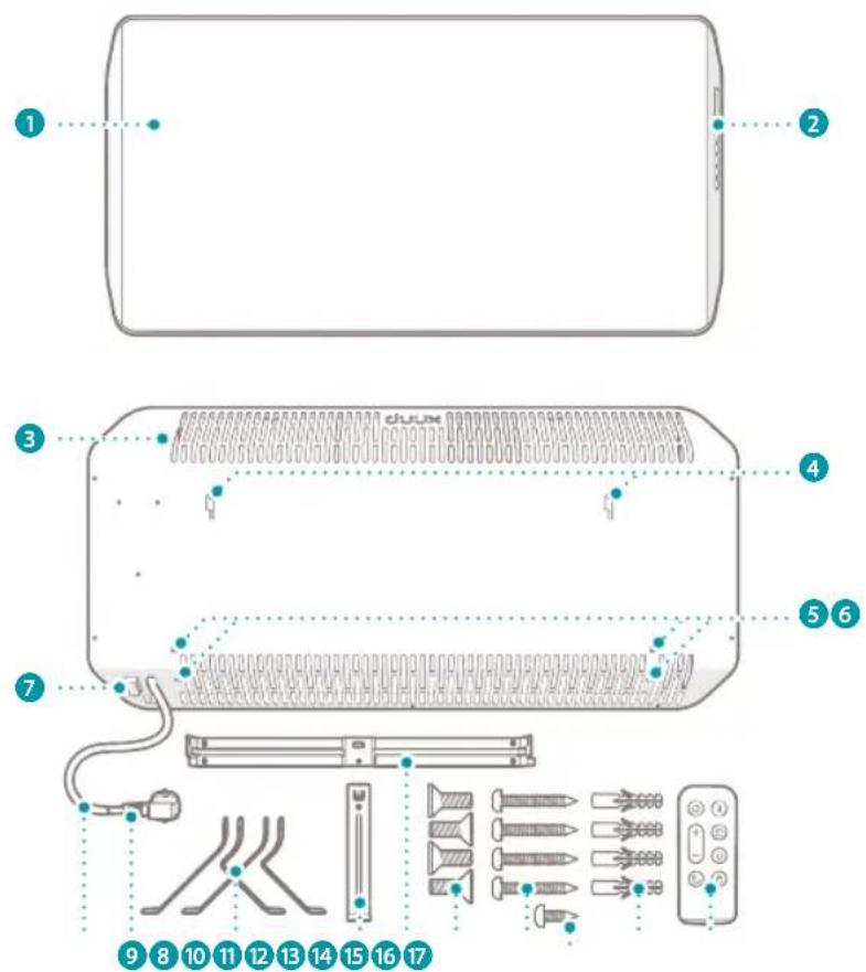
1 Duux Edge Heater
2 Control panel
3 Ventilation slots
4 Mounting slots
5 Rubber protection plugs
6 Mounting holes
7 Power rocker switch
8 Power cord
9 Power plug
10 Set of floor stands (2×)
11 Vertical mounting bracket
12 Horizontal mounting bracket
13 M5 × 10 mm bolt - Philips heads (4×)
14 4.2 × 30 mm screw - Philips head (4×)
15 3.8 × 8mm screw – Philips head (1×)
16 6 × 28 mm plug (4×)
17 Remote control
3.2. Control panel
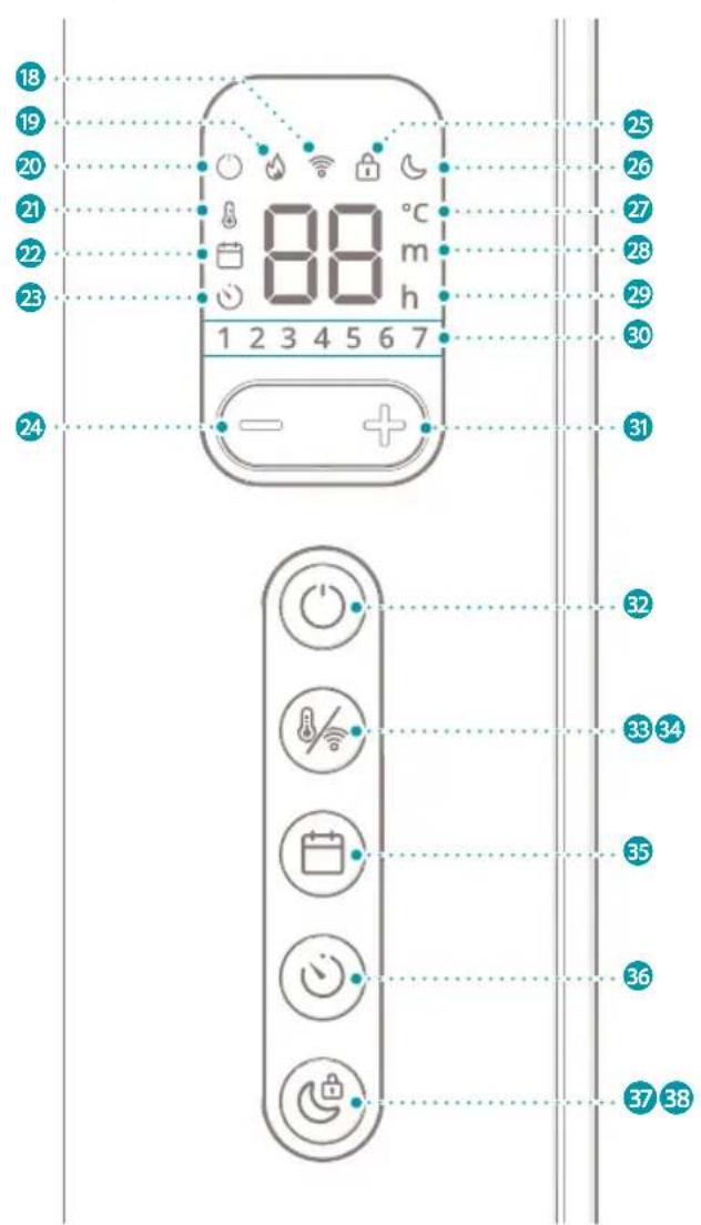
18 Wi-Fi icon
19 Heating icon
20 Standby icon
21 Thermostat icon
22 Schedule icon
23 Timer icon
24 Decrease button
25 Child lock icon
26 Night mode icon
27 Degree Celsius icon
28 Minute icon
29 Hour icon
30 Days of the week icons
31 Increase button
32 Power button
33 Thermostat button
34 Wi-Fi button
35 Schedule button
36 Timer button
37 Night mode button
38 Child lock button
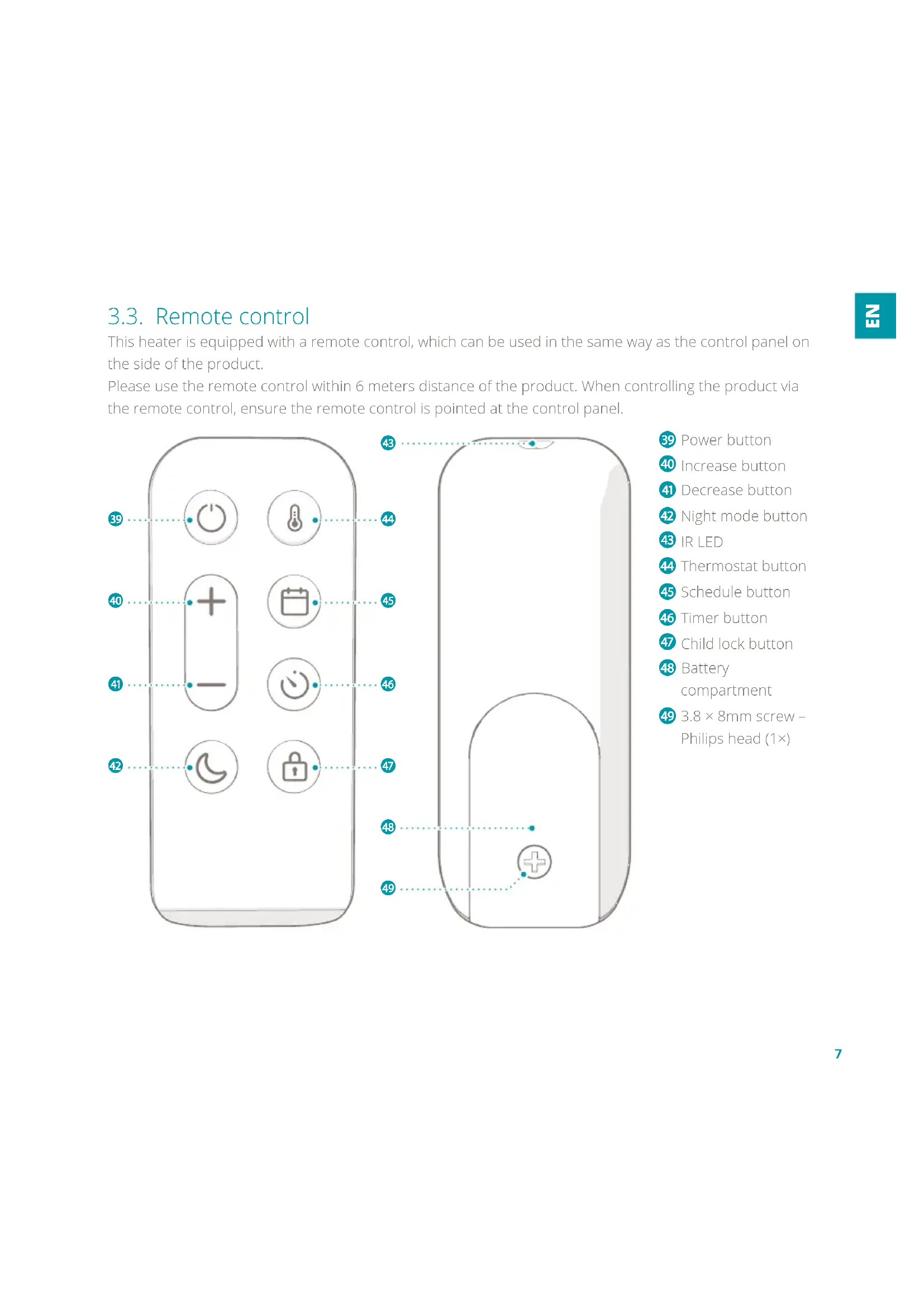
3.3. Remote control
This heater is equipped with a remote control, which can be used in the same way as the control panel on the side of the product.
Please use the remote control within 6 meters distance of the product. When controlling the product via the remote control, ensure the remote control is pointed at the control panel.

39 Power button
40 Increase button
41 Decrease button
42 Night mode button
43 IR LED
44 Thermostat button
45 Schedule button
46 Timer button
47 Child lock button
48 Battery compartment
49 3.8 × 8mm screw - Philips head (1×)
4. Safety instructions
4.1. Safety symbols on the product
Safety symbols provide information on the safe use of the product.
The following symbols can be found on the product:
Symbol Meaning
| CE | Electronic equipment needs to bear the CE mark in order to be marketed in the EU. CE marking shows that a product is assessed before being placed on the market and that it meets EU safety, health and environmental protection requirements. |
 | The European directive 2012 / 19 / CE on Waste Electrical and Electronic Equipment (WEEE), requires that old household electrical appliances must not be disposed in the normal unsorted municipal waste stream.Old appliances must be collected separately in order to optimise recycling and reuse of the materials they contain and to mitigate any consequences to the environment and public health.The crossed out “wheeled bin” symbol on the product reminds you of your obligation, that when you dispose of the appliance it must be separately collected.Consumers should contact their local authority or retailer for information concerning the correct disposal of their old appliance. |
 | Fire hazard. Never cover the product. Covering the product may lead to overheating of the product. |
Symbol Meaning

Indication for a hot surface. Contact may cause burns. Do not touch.

Product in which protection against electric shock does not rely on basic insulation only, but which includes an additional safety precaution in such a way that means are provided for the connection of conductive parts (which are not live parts) to the protective (earthing) conductor in the fixed wiring in such a way that these parts cannot become live in the event of a failure of the basic insulation.
4.2. Safety instructions
4.2.1. Use
AWARNING!
- Risk of electric shock. Unintended use may lead to serious injury or even death. Only use the product as described in this document.
- Risk of internal injury. Always keep button cell batteries, both full and empty, out of reach of children to avoid the chance of swallowing. Dispose of used batteries immediately and safely. Button cell batteries can cause serious internal
chemical burns in as little as two hours when swallowed. Keep in mind that the first symptoms may look like child diseases like coughing or drooling. Seek immediate medical attention when you suspect that batteries have been swallowed.
- Fire hazard. Never use the product on soft surfaces. Soft surfaces may block openings. Always use the product on a flat and dry surface.
- Fire hazard. Never cover the product. Objects may block openings. Keep the space around the product free from objects.
CAUTION!
- Risk of burn. Never touch hot surfaces. The product may become hot while in use. Always let the product cool down before handling the product.
- Risk of falling. Never let the power cord hang over the edge of a table or counter. Someone could trip over the cord or accidentally pull the cord. Always place the power cord on a stable and flat surface.
• Inhalation hazard. Never use paint, cleaning sprays or anti-insect sprays near the product. Always use the product in a clean-air environment. - Risk of short-circuiting. Never use the product if it has been dropped, has come into contact with water, is defective or if the cord or plug is damaged. Return your device to the nearest authorised service point for examination, repair or adjustment.
NOTICE
- Risk of damaging the product. Never use the product in commercial,
industrial or outdoor environments. Always use the product for indoor use only.
4.2.2. Installation
AWARNING!
- Fire hazard. Never use the product near flammable materials or surfaces. The product may become hot while in use. Keep the product at a minimum distance of 1 meter away from flammable materials or surfaces.
- Fire hazard. Never place the product upside down. The openings of the product may become blocked. Always place the product upright.
- Explosion hazard. Never use the product near flammable or explosive substances or fuels. Flammable or explosive substances or fuels may cause an explosion. Only use the product in a clean and well ventilated area.
CAUTION!
- Risk of short-circuiting. Never use an extension cord. Only use the
product on a direct power source.
- Risk of short-circuiting. Never use sockets that do not match the product's power voltage. Before using the product, check the voltage on the unit's rating plate. Only connect the product to sockets that match the product's voltage. If you are not sure whether your connections meet the requirements, consult an electrician or your electricity supplier.
- Risk of short-circuiting. Never connect any other device with high power consumption to the same group. Limit the use of high power consumption products connected to the same group.
- Risk of short-circuiting. Never locate the product immediately below a power outlet. The product may become hot while in use. Always keep the area above the product free from objects and power outlets.
- Risk of short-circuiting. Never use the product in a humid environment. Always use the
product in a clean and dry environment.
NOTICE
- Risk of damaging the product. Never use the product near heat sources. Keep the product away from heat sources.
- Risk of damaging the product. Never use the product in direct sunlight. Direct sunlight may damage the housing of the product.
- Risk of damaging the product. Never pull the power cord to disconnect it from the socket. Always grasp the plug and pull.
- Risk of damaging the product. Remove all the packaging material before assembling or using the product. Leaving packaging material on the product may cause melting of the packaging material and sticking to the product.
- Risk of damaging the product. Never mount the product on the wall with the floor stands placed on the product.
4.2.3. Children and disabled
This product can be used by children aged from 8 years and above and persons with reduced physical, sensory or mental capabilities or lack of experience and knowledge if they have been given supervision or instruction concerning use of the product in a safe way and understand the hazards involved.
AWARNING!
- Tip over hazard. Never let children play with the product. Give children simple instructions on how to use the product beforehand and always supervise them.
- Risk of suffocation. Never let children play with the packaging material. Keep the packaging material out of the reach of children.
- Risk of electric shock. Never let children perform maintenance without supervision. Give children simple instructions on how to use
the product beforehand and always supervise them.
- Risk of burn. Never let children alone unattended with the product in use. Always supervise children when the product is in use.
4.2.4. Maintenance
AWARNING!
- Risk of electric shock. Never perform any maintenance with the product connected to the power source. Disconnect the product from the power source before service and when cleaning the product.
- Fire hazard. Never let the product or power cord become dusty. Regularly clean the product and power cord from dust.
- Risk of electric shock. Never immerse the product in water or other liquids. Follow the cleaning instructions of this manual for the correct performance of maintenance.
- Risk of electric shock. Never handle the product with wet hands. Only handle the product with dry hands.
CAUTION!
- Risk of short-circuiting. Never open the product yourself for maintenance. This product may only be opened for maintenance by an authorised technician.
NOTICE
- Risk of damaging the product. Never use cleaning solvents or abrasives to clean the product. Using the wrong cleaning products may damage the housing of the product. Always use the correct cleaning method specified in this user manual.
4.2.5. Storage & transport
NOTICE
- Risk of damaging the product. Incorrect storage may damage the product or electric circuit of the product. Always store the product in the original packaging and keep in a clean, dry place.
5. Installation
5.1. Package content
Check the package contents. If any parts are missing or damaged, please contact your supplier.
1 × Horizontal mounting bracket
1 × Vertical mounting bracket
2 × Floor stand
1 × Remote control
4 × M5 × 10 mm bolt - Philips heads (4×)
4 × 4.2 × 30 mm screw - Philips head (4×)
1 × 3.8 × 8mm screw – Philips head (1×)
4×6×28 mm plug
NOTICE
- Risk of damaging the product. Remove all the packaging material before assembling or using the product. Leaving packaging material on the product may cause melting of the packaging material and sticking to the product.
5.2. Installation of the product
WARNING!
- Fire hazard. Never use the product near flammable materials or surfaces. The product may become hot while in use. Keep the product at a minimum distance of 1 meter away from flammable materials or surfaces.
CAUTION!
- Risk of short-circuiting. Never use an extension cord. Only use the product on a direct power source.
- Risk of short-circuiting. Never locate the product immediately below a power outlet. The product may become hot while in use. Always keep the area above the product free from objects and power outlets.
- Risk of short-circuiting. Never use the product in a humid environment. Always use the product in a clean and dry environment.
This product can be used with the floor stand or mounting bracket.
5.2.1. Required tools
- Screwdriver
- Power drill
- 6 mm drill bit
- Hammer
- Pencil
- Measuring tape
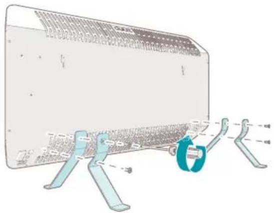
5.2.2. Assembling the product
natural_image
Technical illustration of a mechanical component with attached parts and dimension lines (no text or symbols)-
Carefully place the product on a soft, stable and flat surface.
-
Remove the rubber protection plugs 5 from the floor stand mounting holes 6.
-
Place the first floor stand 10 on the product and align the holes on the floor stand with the mounting holes 6.
-
Attach the first floor stand 10 to the product with the bolts 13 using a screwdriver.
-
Perform step 3. and 4. for the second floor stand.
-
Put the product in an upright position on the floor.
- The product is now ready to use.
5.2.3. Mounting the mounting bracket
NOTICE
- Never mount the product on the wall with the floor stands placed on the product.
• Take a minimal spacing into account when mounting the mounting bracket. See the next image.
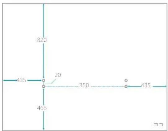
-
Determine the desired position of the mounting bracket ⑫ and mark the 4 holes of the mounting bracket accordingly.
-
Drill a hole with a diameter of 6 mm at each of the 4 marks.
-
Place a plug 16 into each of the drilled holes and use a hammer to fix the plug.
NOTICE
- Make sure that the plug is up to the sealing ring into the hole.

natural_image
Diagram of a mechanical device with a rotating shaft and base, showing internal components and motion direction (no text or symbols)-
Align the holes in the horizontal mounting bracket 12 with the holes in the wall.
-
Attach the horizontal mounting bracket 12 to the wall with the screws 14 using a screwdriver.
natural_image
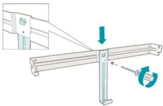
Mechanical assembly diagram showing a lever mechanism with directional arrows indicating motion (no text or symbols)-
Align the hole in the vertical mounting bracket 11 with the holes in the horizontal mounting bracket 12.
-
Attach the vertical mounting bracket 11 to the horizontal bracket 12 with a screw 15 using a screwdriver.

natural_image
Illustration of a device with a blue lightning bolt symbol inserted into a rectangular housing, showing internal components and an inset view of a mechanical assembly (no text or symbols present)- Place the mounting slots 4 over the mounting hooks of the horizontal mounting bracket 12.
- A click is heard when the mounting bracket hooks are in the mounting slots 4.
-
Shift the product over the mounting bracket hooks to the left until a stop is felt.
-
Shift the product downwards until a click is heard.
- The product fixates itself onto the horizontal mounting bracket 12.
NOTICE
- The product is mounted correctly if you hear a click sound.
5.2.4. Installing the remote control
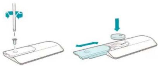
natural_image
Illustration showing two steps of a medical or laboratory procedure: one with a needle inserted into a device, the other with a magnified view of a device (no text or symbols present)- Turn the remote control 17 upside down.
- Unscrew the 3.8 × 8 mm screw 49 to open the battery compartment 48.
- Place the battery in the battery compartment with the plus-side of the battery facing up.
- Fasten the 3.8 × 8 mm screw 49 to close the battery compartment.
5.3. Setting the time and day of the week
Setting or adjusting the time and day of the week is done as follows:
-
Simultaneously press and hold the schedule button 45 and the timer button 46 for 5 seconds.
-
The product makes a beep sound.
-
Number "1" in the day of the week icons 1 starts flashing.
-
Press the increase button 40 or decrease button 41 and choose the number corresponding with the desired day of the week.
| 1 | Monday | 5 | Friday |
| 2 | Tuesday | 6 | Saturday |
| 3 | Wednesday | 7 | Sunday |
| 4 | Thursday |
-
Press the schedule button 45 to confirm the selected number.
-
The product makes a beep sound when the selected number is confirmed.
- The selected number lights up.
- After a few seconds, the product enters the hour editing setting.
-
Number "00" starts flashing on the display along with the hour icon h
-
Press the increase button 40 or the decrease button 41 and choose the number corresponding with the desired hours of the day - 00 to 23.
-
Press the schedule button 45 to confirm the selected number.
-
The product makes a beep sound when the selected number is confirmed.
- After a few seconds, the product enters the minute editing setting.
-
Number "00" starts flashing on the display along with the minute icon m
-
Press the increase button 40 or decrease button 41 and choose the number corresponding with the desired minutes of the hour - 00 to 59.
-
Press the schedule button 45 to confirm the selected number.
-
The product makes a beep sound when the selected number is confirmed.
- The display returns to showing the ambient temperature.
- The setup of the time and day of the week is complete.
NOTICE
• The days of the week and time need to be set first before the schedule function of the product can be used.
- If no buttons are pressed for 7 seconds during the active setup process, the setup is cancelled.
- The setup process can be cancelled by pressing and holding the schedule button and the timer button for 5 seconds. The product makes a beep sound and the day of the week icons
1 2 3 4 5 6 7 flash 7 times to indicate that the time and day of the week have not been set.
6. Wi-Fi and Duux app operation
6.1. Installing the Duux app
-
Scan the QR code below or search for "Duux" in the App Store or Google Play Store and install the application.
-
Once installed, please log in or create a Duux app account and follow the steps to complete the registration.
- Open the Duux app and click "Add Duux device" on the main screen, or use the "+" button in the top right corner to add a new device.
- Search for "Edge".
- Follow the instructions in the app on how to complete the pairing process.
Google Play store Apple App store


6.1.1. Disconnecting the product from Wi-Fi
NOTICE
• The product must be in standby mode to disconnect the product from Wi-Fi.
-
Press and hold the Wi-Fi button 34 for ±5 seconds.
-
The Wi-Fi disconnects from the product.
- The Wi-Fi icon starts flashing and searches for devices to pair with.
7. Use
7.1. Product modes
- Standby mode: The product is connected to the power source but not turned on. The product can receive input from the control panel, remote control or Duux app. The standby icon lights up.
- Sleep mode: The product is turned on. The night mode icon lights up at half of the brightness. The other icons are not shown on the display. The product produces no sound signals.
- Awake mode: The product is turned on. Press any button to activate the awake mode from the sleep mode. Press the power button
39 to activate the awake mode from the standby mode. The display shows the room temperature and all active function icons light up.
7.2. Turning on the product
- Plug the power plug 9 into the power source.
- Toggle the power rocker switch ⑦ on the product from O to I.
- The product makes a beep sound.
- The product is now in standby mode.
- The standby icon on the display lights up.
- Press the power button 32 on the product or the remote control to turn on the product.
- The product makes a beep sound.
- The standby icon turns off.
- The product resumes in the thermostat function with the previous set temperature.
- The display shows the room temperature along with the thermostat icon 🔒
NOTICE
- When the product is used for the first time, the product will start in the thermostat function with a default set temperature of 20^ .
7.3. Thermostat function
The thermostat function lets the user chose the desired room temperature.
The product actively heats the room to maintain the chosen temperature. The thermostat function is on by default.
7.3.1. Setting the temperature
-
Press the thermostat button 44
-
The product makes a beep sound.
- The current set temperature and the thermostat icon starts flashing.
NOTICE
- Step 1 is optional. To adjust the temperature directly, start with step 2.
-
Press the increase button 40 or decrease button 41 to adjust the temperature.
-
Wait for 3 seconds.
- The set temperature and the thermostat icon
stop flashing and light up for 2 seconds,
showing that the chosen value is confirmed.
- The product returns to awake mode.
- The thermostat icon lights up on the display to indicate that the thermostat function is activated.
NOTICE
- When the heater is actively heating to maintain the set temperature, the heating icon lights up on the display.
- The thermostat function can be combined with the timer function.
7.3.2. Open window detection
When a sudden drop of 5^ C in temperature within 10 minutes is detected, the product will stop heating to prevent unnecessarily heating. The product suspects an open window nearby. The product makes a long beep sound and all the function icons on the display turn off. The display shows the word "OPEN" continuously for 1 minute.
During the 1 minute wait, press any button to cancel the product from entering standby mode. The product will resume the current function settings.
After 1 minute, the product makes a beep sound and enters standby mode while the word "OPEN" remains on the display.
Press the power button 39 to return the product into awake mode.
7.4. Timer function
The timer function can be used in two ways:
- Turn on timer: Turns on the product automatically at a chosen time. After a set amount of time, the product enters awake mode.
- Turn off timer: Turns off the product automatically at a chosen time. After a set amount of time, the product enters standby mode.
NOTICE
- The timer function can be used without a day and time being set.
• The timer function can be combined with the thermostat function. - The timer function cannot be combined with the schedule function. Activating the timer function deactivates the schedule function.
7.4.1. Setting the turn on timer
NOTICE
- The product must be in standby mode to activate this function.
-
Press and hold the timer button 46 for 3 seconds.
-
The product makes a beep sound.
-
Number "0" starts flashing on the display along with the timer icon 😊
-
Press the increase button 40 or the
decrease button 41 and choose the number corresponding with the desired amount of hours after which the product automatically turns on - 1 to 24.
- Wait for 3 seconds.
- The set time and the timer icon stop flashing and lights up for 2 seconds, showing that the chosen value is confirmed.
- The product returns to standby mode.
- The timer icon lights up on the display to indicate that the timer function is activated.
7.4.2. Deactivating the turn on timer
NOTICE
- The product must be in standby mode to deactivate the turn on timer function.
-
Press and hold the timer button 46 for 3 seconds.
-
The product makes a beep sound.
- The timer icon is not shown on the display anymore to indicate that the timer function is deactivated.
7.4.3. Setting the turn off timer
NOTICE
- The product must be in awake mode to activate this function.
-
Press the timer button 46.
-
The product makes a beep sound.
-
Number "0" starts flashing on the display along with the timer icon 😊
-
Press the increase button 40 or the decrease button 41 and choose the number corresponding with the desired amount of hours after which the product automatically turns off - 1 to 24.
-
Wait for 3 seconds.
- The set time and the timer icon stop flashing and lights up for 2 seconds, showing that the chosen value is confirmed.
- The product returns to awake mode.
- The timer icon lights up on the display to indicate that the timer function is activated.
7.4.4. Deactivating the turn off timer
NOTICE
- The product must be in awake mode to deactivate the turn off timer function.
-
Press and hold the timer button 46 for 3 seconds.
-
The product makes a beep sound.
- The timer icon is not shown on the display anymore to indicate that the timer function is deactivated.
7.5. Schedule function
7.5.1. Preset schedules
NOTICE
- The timer function cannot be combined with the schedule function.
The preset schedules are divided into settings
relating to the room temperature, time, and day of the week.
The default high temperature value is set at 23^ C and low temperature is 18^ C.
You can adjust the desired temperature per time slot.
See chapter Setting a schedule for instructions.
You can select 3 different pre-set schedules: home, office or cabin mode.
Home mode
| Day 6:00 | 8:00 | 16:00 | 23:00 |
| -8:00 | -16:00 | -23:00 - 6:00 | |
| Monday - Friday | 23 °C | 18 °C | 23 °C 18 °C |
| Saturday & Sunday | 23 °C | 23 °C | 23 °C 18 °C |
Office mode
| Day 7:00 - 17:00 17:00 - 7:00 |
| Monday - Friday 23 °C 18 °C |
| Saturday & Sunday | Off Off |
Cabin mode
Cabin mode is designed to provide a constant temperature at your home while you are on a trip to a cabin or stay in a hotel room.
When the cabin schedule is activated, the schedule activates heating during the day and cooling down at night.
NOTICE
- By default the schedule lasts for 30 days. After 30 days the product will continuously maintain a low temperature of 18^ for 5 more months.
| Cabin mode | ||
| Day | 8:00 - 22:00 | 22:00 - 8:00 |
| Monday | 23 °C 18 °C | |
| - Sunday | ||
7.5.2. Activating a schedule
- Press the schedule button 45.
- The product makes a beep sound.
- The letter "H" starts flashing on the display along with the schedule icon 📋
- Press the increase button 40 or the decrease button 41 and choose from the 4 available options: H (Home), O (Office), C (Cabin) or -- (Off).
- Wait for 3 seconds.
- The selected schedule stops flashing and lights up for 2 seconds, showing that the chosen value is confirmed.
NOTICE
• The following applies to the Home or Office mode.
- The product returns to awake mode.
- The schedule icon lights up on the display to indicate that the schedule function is activated.
NOTICE
• The following applies to the Cabin mode.
- The product makes a beep sound.
-
The number "30" starts flashing on the display.
-
Press the increase button 40 or decrease button 41 and select the desired duration of the schedule in days - 1 to 30 days.
-
Wait for 3 seconds.
- The set number stops flashing and lights up for 2 seconds, showing that the chosen value is confirmed.
- The product returns to awake mode.
- The schedule icon lights up on the display to indicate that the schedule function is activated.
NOTICE
- Press the thermostat button 44 to check the current set temperature of the schedule.
- Pressing the thermostat button 44 does not change the temperature setting.
7.5.3. Adjusting the temperature of a schedule
To overwrite the temperature of a schedule, see chapter Setting the temperature.
Adjusting the temperature via the thermostat function temporarily overwrites the set temperature of the schedule without deactivating the schedule function. The overwritten temperature remains until the start of the next time slot of the preset schedule.
The thermostat icon and the schedule icon light up on the display to show that a temporary change in temperature is made while the schedule function is active.
7.5.4. Deactivating a schedule
-
Press and hold the schedule button 45 for 3 seconds.
-
The product makes a beep sound.
- The schedule icon is not shown on the display anymore to indicate that the schedule function is deactivated.
7.5.5. Custom schedules
It is possible to change the predefined time slots and the default high and low temperatures of the schedules in the Duux app. Make sure the product is connected to Wi-Fi - see chapter
Wi-Fi and Duux app operation – and follow the instructions.
7.6. Night mode function
When the product is in night mode, the display is at half of the brightness and the sound signal of the product is deactivated.
7.6.1. Activating the night mode
-
Press the night mode button 42.
-
The product makes a beep sound.
- The night mode icon lights up on the display to indicate that the night mode function is activated.
-
The display dims to half of the brightness.
-
The sound of the product is deactivated.
- After 10 seconds, the product enters the sleep mode.
- The display is turned off except for the night mode icon 🌐
NOTICE
• To change settings while in night mode, first press any button to enter awake mode.
- The night mode does not change the functions of the product.
7.6.2. Deactivating the night mode
-
Press the night mode button 42.
-
The product makes a beep sound.
- The night mode icon is not shown on the display anymore to indicate that the night mode function is deactivated.
- The display lights up at full brightness.
- The sound of the product is activated.
7.7. Child lock function
The child lock function prevents users from making unwanted changes to the settings. The settings cannot be changed when the child lock function is activated.
7.7.1. Activating the child lock
-
Press and hold the child lock button 47 for 5 seconds.
-
The product makes a beep sound.
- The child lock icon lights up on the display
to indicate that the child lock function is activated.
7.7.2. Deactivating the child lock
-
Press and hold the child lock button 47 for 5 seconds.
-
The product makes a beep sound.
- The child lock icon is not shown on the display to indicate that the child lock function is deactivated.
8. Turning off the product
8.1. Entering standby mode
NOTICE
- Entering standby mode clears any active shut down timer or schedule function.
-
Press the power button 39 to turn off the product.
-
The product makes a beep sound.
- The product is now in standby mode.
8.2. Power off
NOTICE
- When the product is turned off, all settings will be reset and functions will be deactivated.
- Toggle the power rocker switch 7 on the product from I to O.
- The product is now turned off.
- Unplug the power plug 9 from the power source.
9. Maintenance
▲ WARNING!
- Risk of electric shock. Never perform any maintenance with the product connected to the power source. Disconnect the product from the power source before service and when cleaning the product.
9.1. Cleaning
WARNING!
- Risk of electric shock. Never immerse the product in water or other liquids. Follow the cleaning instructions of this manual for the correct performance of maintenance.
NOTICE
- Risk of damaging the product. Never use cleaning solvents or abrasives to clean the product. Using the wrong cleaning products may damage the housing of the product. Always use the correct cleaning method specified in this user manual.
Clean the product every week.
- Clean the outside of the product with a soft, slightly damp cloth.
- Dry the outside of the product with a soft, dry cloth.
9.2. Storing
When the product is not used for multiple months, please clean all the components.
Store the product in the original packaging and keep in a clean, dry place.
9.3. Spare parts
WARNING!
- Risk of electric shock. Never perform any maintenance with the product connected to the power source. Disconnect the product from the power source before service and when cleaning the product.
CAUTION!
- Risk of short-circuiting. Never open the product yourself for maintenance. This product may only be opened for maintenance by an authorised technician.
Spare parts and accessories can be requested at the point of purchase or local distributor.
10. FAQ
Error code Possible cause Possible solution
E0 The NTC is disconnected. Please contact a certified Duux service provider.
E1 The NTC has short circuited. Please contact a certified Duux service provider.
E2 The tip-over switch has been triggered. Disconnect the product from the power source. Place the product upright on a stable and flat surface. Connect the product to the power source.
If problems persist, please contact your supplier.
11.Warranty
Duux products have a 24-month guarantee from the time of purchase, provided that they are installed and maintained correctly as indicated in this user manual. Warranty will be void if the product has been improperly operated, stored or used other than described in this manual. This includes opening the device and water damage.
Claims under the guarantee must always be made via the supplier of your Duux product. Products with a defect caused by the production process and within the guarantee period after purchase will be assessed by Duux.
If you notice a defect, please first consult the user manual and the online FAQ at www.duux.com.
12.Disposal
CAUTION!
- Risk of short-circuiting. Never open the product yourself for maintenance. This product may only be opened for maintenance by an authorised technician.
If the product is defective, please contact your supplier. It may still be possible to repair the product. If you still need to dispose the product, please follow the local regulations.

The European directive 2012 / 19 / CE on Waste Electrical and Electronic Equipment (WEEE), requires that old household electrical appliances must not be disposed in the normal unsorted municipal waste stream.
Old appliances must be collected separately in order to optimise recycling and reuse of the materials they contain and to mitigate any consequences to the environment and public health. The crossed out “wheeled bin” symbol on the product reminds you of your obligation, that when you dispose of the appliance it must be separately collected.
Consumers should contact their local authority or retailer for information concerning the correct disposal of their old appliance.
13. Simplified EU declaration of conformity
Hereby, Duux declares that this ambient radio equipment complies with Directive 2014/53/EU. The full text of the EU Declaration of Conformity is available at the following internet address: www.duux.com/doc
14. Technical specifications
| Product name | Duux Edge Heater Duux Edge Heater Duux Edge Heater | ||
| Model number | DXCH10, DXCH11 DXCF12, DXCH13 DXCH14, DXCH15 | ||
| Measurements (d × w × h) | 65 × 816 × 400 mm | 65 × 816 × 400 mm | 65 × 816 × 400 mm |
| Weight | 7.55 kg | 7.65 kg | 7.85 kg |
| Input power | 220 - 240 VAC ; 50 Hz | ||
| Power | 500 - 1000 W | 750 - 1500 W | 1000 - 2000 W |
| Battery type remote control | CR2032 CR2032 CR2032 | ||
| Duux app version | 2.4.0 | ||
| Capacity | 8 - 15 m2 | 11 -20 m2 | 21 -30 m2 |
| Ambient temperature | 5 °C - 36 °C | 5 °C - 36 °C | 5 °C - 36 °C |
| Heat output | |||
| Nominal heat output 1000 W | 1500 W | 2000 W | |
| Minimum heat output 500 W | 750 W | 1000 W | |
| Maximum continuous heat output 1000 W | 1500 W | 2000 W | |
| Auxiliary electricity consumption | |||
| At nominal heat output 1000 Wh | 1500 Wh | 2000 Wh | |
| At minimum heat output 500 Wh | 750 Wh | 1000 Wh | |
| In standby mode | 0.8 Wh | 0.8 Wh | 0.8 Wh |
The most important data of the product can also be found on the rating plate. The rating plate is located on the back of the product.
The appearance and specification of the device may be changed without notice.

1 Duux Edge
Verwarmingstoestel
2 Bedieningspaneel
3 Ventilatiesleuven
4 Montagesleuven
5 Rubberen beschermstoppen
6 Bevestigingsgaten
7 Tuimelschakelaar aan/uit
8 Stroomkabel
9 Stekker
10 Set vloersteunen (2×)
11 Verticale montagebeugel
12 Horizontale montagebeugel
13 M5 × 10 mm bout - kruiskop (4×)
14 4,2 × 30 mm schroef - kruiskop (4×)
15 3,8 × 8mm schroef - kruiskop (1×)
16 6 × 28 mm stekker (4×)
17 Afstandsbediening
3.2. Bedieningspaneel

18 Pictogram wifi
19 Pictogram verwarming
20 Pictogram stand-by
21 Pictogram thermostaat
22 Pictogram programma
23 Pictogram timer
24 Knop verlagen
25 Pictogram kinderslot
26 Pictogram nachtmodus
27 Pictogram graden Celsius
28 Pictogram minuut
29 Pictogram uur
30 Pictogrammen dagen van de week
31 Knop verhogen
32 Aan/uit-knop
33 Thermostaatknop
34 Wifi-knop
35 Programmaknop
36 Timerknop
37 Nachtmodusknop
38 Kinderslotknop
3.3. Afstandsbediening
39 Aan/uit-knop
40 Knop verhogen
41 Knop verlagen
42 Nachtmodusknop
43 IR-LED
44 Thermostaatknop
45 Programmaknop
46 Timerknop
47 Kinderslotknop
48 Batterijvak
49 3,8 × 8mm schroef - kruiskop (1×)
natural_image
Technical illustration of a mechanical clamp or bracket assembly with no visible text or symbolsnatural_image
Diagram of a mechanical device with a tool and rotating component, no text or symbols presentnatural_image
Mechanical assembly diagram showing a lever mechanism with force arrows and rotation (no text or symbols)natural_image
Illustration of a briefcase with a downward arrow indicating compression or dislocation, shown with an inset close-up of the handle (no text or symbols)natural_image
Diagram showing two steps of a medical or laboratory procedure: adding a needle to a device and adding a component to a device (no text or symbols present)
natural_image
Technical illustration of a mechanical component with attached clamping elements (no text or symbols)natural_image
Diagram of a mechanical device with a rotating shaft and internal components, showing no text or symbols.natural_image
Mechanical assembly diagram showing a lever mechanism with a rotating knob and directional arrows (no text or symbols)natural_image
Illustration of a device with a downward arrow and a magnified inset showing a mechanical assembly (no text or symbols)natural_image
Diagram showing two steps of a medical or laboratory procedure: one with needle insertion and another with a magnified view of a device (no text or symbols present)
natural_image
Technical line drawing of a mechanical component with attached parts and a magnified inset showing a circular feature (no text or symbols)natural_image
Diagram of a mechanical device with a rotating component and a blue-green rotation arrow (no text or symbols)natural_image
Mechanical assembly diagram showing a metal frame with a rotating knob and directional arrows (no text or symbols)natural_image
Illustration of a device with a downward arrow indicating compression or dislocation, shown with an inset close-up of its component (no text or symbols present)natural_image
Illustration showing two steps of a medical or laboratory procedure: one with a needle inserted into a device, the other with a magnified view of a device (no text or symbols present)
natural_image
Technical illustration of a mechanical component with attached clamps and a spring, showing no text or symbols.natural_image
Diagram of a mechanical device with a rotating shaft and base, showing internal components and motion direction (no text or symbols)natural_image
Mechanical assembly diagram showing a lever mechanism with rotating components (no text or symbols)natural_image
Illustration of a device with a downward arrow and connector, shown with an inset view of a mechanical assembly (no text or symbols)natural_image
Two-step diagram showing a tool tip and a mechanical component with arrows indicating motion (no text or symbols)
GB - Original user manual
V1.1 - 07/21
Designed in The Netherlands bij Duux BV. Made in P.R.C. Duux BV, P.O. Box 145, 5400 AC Uden Netherlands, www.duux.com
© 2021 Duux. All rights reserved.
DUUX® is a trademark of Duux BV,
registered in the EU and other countries.
The brand cited belongs exclusively to the respective owners.
Specifications are subject to modification without notice.
duux®


- Edge
- Thank you for choosing Duux.
- Table of content
- About this manual 4
- Product overview 4
- Product description 5
- Safety instructions 8
- Wi-Fi and Duux app operation 18
- Use 19
- Turning off the product 24
- Maintenance 25
- FAQ 26
- Warranty 26
- Disposal 27
- Simplified EU declaration of conformity 27
- Technical specifications 28
- About this manual
- Language
- Used symbols in this manual
- AWARNING!
- CAUTION!
- NOTICE
- Product overview
- Intended use
- Product description
- Main parts
- Control panel
- Remote control
- Safety instructions
- Safety symbols on the product
- Symbol Meaning
- Safety instructions
- Use
- Installation
- Children and disabled
- Maintenance
- Storage & transport
- Installation
- Package content
- Installation of the product
- WARNING!
- Required tools
- Assembling the product
- Mounting the mounting bracket
- Installing the remote control
- Setting the time and day of the week
- Wi-Fi and Duux app operation
- Installing the Duux app
- Disconnecting the product from Wi-Fi
- Use
- Product modes
- Turning on the product
- Thermostat function
- Setting the temperature
- Open window detection
- Timer function
- Setting the turn on timer
- Deactivating the turn on timer
- Setting the turn off timer
- Deactivating the turn off timer
- Schedule function
- Preset schedules
- Cabin mode
- Activating a schedule
- Adjusting the temperature of a schedule
- Deactivating a schedule
- Custom schedules
- Night mode function
- Activating the night mode
- Deactivating the night mode
- Child lock function
- Activating the child lock
- Deactivating the child lock
- Turning off the product
- Entering standby mode
- Power off
- Maintenance
- ▲ WARNING!
- Cleaning
- Storing
- Spare parts
- FAQ
- Error code Possible cause Possible solution
- 11.Warranty
- 12.Disposal
- Simplified EU declaration of conformity
- Technical specifications
- Bedieningspaneel
- Afstandsbediening
Brand : DUUX
Model : Edge 2000
Category : Heating