
DJM750MK2 - DJ Equipment PIONEER - Free user manual and instructions
Find the device manual for free DJM750MK2 PIONEER in PDF.
| Product type | 4-channel DJ mixer |
| Brand | PIONEER |
| Model | DJM-750MK2 |
| Dimensions (W × H × D) | 320 mm × 107.9 mm × 387.9 mm |
| Weight | 6.6 kg |
| Power supply | AC 110 V to 240 V, 50/60 Hz |
| Power consumption (standby) | 0.3 W |
| Sampling frequency | 48 kHz |
| A/D converter (channels) | 32 bits |
| S/N ratio (LINE) | 105 dB |
| Total harmonic distortion (LINE → MASTER1) | 0.005 % |
| Channel equalizer | HI, MID, LOW: -26 dB to +6 dB |
| Built-in effects | SOUND COLOR FX, BEAT FX, SEND/RETURN |
| Inputs | 4 × PHONO/LINE (RCA), 1 × MIC (XLR/TRS), 1 × RETURN (TS), 1 × USB (Type B) |
| Outputs | 1 × MASTER1 (XLR), 1 × MASTER2 (RCA), 1 × BOOTH (TRS), 1 × SEND (TS), 1 × PHONES (6.35 mm and 3.5 mm jacks) |
| USB | Type A (5 V/2.1 A for mobile device), Type B (for computer) |
| Operating temperature | +5 °C to +35 °C |
| Maintenance and cleaning | Clean jacks and plugs with a dry cloth; do not use solvents |
| Safety | Do not expose to water, do not open the case, use ground connection, leave 5 cm ventilation around |
| Spare parts and repairability | Repairs by qualified personnel only; cables and adapters are standard |
| General information | Compatible with rekordbox dj and rekordbox dvs (license key included) |
Frequently Asked Questions - DJM750MK2 PIONEER
User questions about DJM750MK2 PIONEER
0 question about this device. Answer the ones you know or ask your own.
Ask a new question about this device
Download the instructions for your DJ Equipment in PDF format for free! Find your manual DJM750MK2 - PIONEER and take your electronic device back in hand. On this page are published all the documents necessary for the use of your device. DJM750MK2 by PIONEER.
USER MANUAL DJM750MK2 PIONEER
For FAQs and other support information for this product, visit the above site.
Operating Instructions (Quick Start Guide)
If you want to dispose this product, do not mix it with general household waste. There is a separate collection system for used electronic products in accordance with legislation that requires proper treatment, recovery and recycling.
Private households in the member states of the EU, in Switzerland and Norway may return their used electronic products free of charge to designated collection facilities or to a retailer (if you purchase a similar new one).
For countries not mentioned above, please contact your local authorities for the correct method of disposal.
By doing so you will ensure that your disposed product undergoes the necessary treatment, recovery and recycling and thus prevent potential negative effects on the environment and human health.
K058b_A1_En
CAUTION
TO PREVENT THE RISK OF ELECTRIC SHOCK, DO NOT REMOVE COVER (OR BACK). NO USER-SERVICEABLE PARTS INSIDE. REFER SERVICING TO QUALIFIED SERVICE PERSONNEL. D3-4-2-1-1_B1_En
WARNING
This equipment is not waterproof. To prevent a fire or shock hazard, do not place any container filled with liquid near this equipment (such as a vase or flower pot) or expose it to dripping, splashing, rain or moisture. D3-4-2-1-3_A1_En
WARNING
This product equipped with a three-wire grounding (earthed) plug - a plug that has a third (grounding) pin. This plug only fits a grounding-type power outlet. If you are unable to insert the plug into an outlet, contact a licensed electrician to replace the outlet with a properly grounded one. Do not defeat the safety purpose of the grounding plug. D3-4-2-1-6_A1_En
For Finland customers
For Norway customers
For Sweden customers
Apparaten skall anslutas till jordat uttag
For Denmark customers
To prevent a fire hazard, do not place any naked flame sources (such as a lighted candle) on the equipment.
D3-4-2-1-7a_A1_En
Operating Environment
Operating environment temperature and humidity: +5 °C to +35 °C (+41 °F to +95 °F); less than 85 %RH (cooling vents not blocked)
Do not install this unit in a poorly ventilated area, or in locations exposed to high humidity or direct sunlight (or strong artificial light). D3-4-2-1-7c*_A2_En
When using this product, confirm the safety information shown on the bottom of the unit.
D3-4-2-2-4_B1_En
CAUTION
The ⬇ switch on this unit will not completely shut off all power from the AC outlet. Since the power cord serves as the main disconnect device for the unit, you will need to unplug it from the AC outlet to shut down all power. Therefore, make sure the unit has been installed so that the power cord can be easily unplugged from the AC outlet in case of an accident. To avoid fire hazard, the power cord should also be unplugged from the AC outlet when left unused for a long period of time (for example, when on vacation).
D3-4-2-2-2a*_A1_En
WARNING
Store small parts out of the reach of children and infants. If accidentally swallowed, contact a doctor immediately.
D41-6-4_A1_En
This product is for general household purposes. Any failure due to use for other than household purposes (such as long-term use for business purposes in a restaurant or use in a car or ship) and which requires repair will be charged for even during the warranty period.
K041_A1_En
VENTILATION CAUTION
When installing this unit, make sure to leave space around the unit for ventilation to improve heat radiation (at least 5 cm at rear, and 5 cm at each side).
D3-4-2-1-7d*_A1_En
The graphical symbol ∼ placed on the product means alternating current.
The graphical symbol == placed on the product means direct current.
The graphical symbol □ placed on the product means Class II equipment.
D3-8-2-4_A1_En
CAUTION
This product is evaluated in moderate and tropical climate condition. D3-8-2-1-7a_A1_En
POWER-CORD CAUTION
Handle the power cord by the plug. Do not pull out the plug by tugging the cord and never touch the power cord when your hands are wet as this could cause a short circuit or electric shock. Do not place the unit, a piece of furniture, etc., on the power cord, or pinch the cord. Never make a knot in the cord or tie it with other cords. The power cords should be routed such that they are not likely to be stepped on. A damaged power cord can cause a fire or give you an electrical shock. Check the power cord once in a while. When you find it damaged, ask your nearest service center or your dealer for a replacement. S002*_A1_En
S002*_A1_En
Contents
How to read this manual
Thank you for purchasing this Pioneer DJ product.
Read this manual and the Operating Instructions that is available on the Pioneer DJ site before using the product. Both contain important information that you should understand to properly use the product.
- In this manual, names of channels and buttons on the product, menus in the software, etc., are enclosed in square brackets ([ ]). (e.g. [MASTER] channel, [ON/OFF], [Start] menu)
- Screens, external appearance, and software and hardware specifications described in this manual are based on the product that is still under development and may differ from the final specifications.
- Depending on your operating system, the web browser settings, etc., the procedures described in this manual may differ from actual operations.
This manual provides brief descriptions of the part names and the connection between the unit and peripherals. For more instructions on how to use this product, refer to the Operating Instructions for this product.
- For obtaining the Operating Instructions for this product, see Obtaining the Operating Instructions on page 5.
01 Before start
Features 5
Accessories....5
Obtaining the Operating Instructions....5
02 Part names and functions
Rear panel 6
Control Panel 7
03 Connections
Connecting input terminals....9
Connecting output terminals 10
04 Operation
Basic Operation 11
Changing the settings.... 11
05 Additional information
Troubleshooting....12
Trademarks and registered trademarks....12
Cautions on copyrights....12
Specifications.... 13
Before start
Features
This 4-channel DJ mixer is the next model in the DJM series from Pioneer DJ, the world standard in the disco and club scene. It supports various types of DJ performances by incorporating the EQ FADER CURVE, SOUND COLOR FX, BEAT FX, and SEND/RETURN functions for mixing that were newly developed for the DJM-900NXS2, which is equipment for permanent installation in a club. This mixer provides strong support for any DJ performance by featuring a high sound quality, highly reliable design, and panel layout providing high operability, and supporting connections to a wide range of devices including a USB sound card capable of connecting with a PC, Mac, or iOS device.
Accessories
- Power cord
- USB cable
- Operating Instructions (Quick Start Guide) (this document)
• Warranty (for some regions) 1
• License key card (rekordbox dj, rekordbox dvs)
1 The included warranty is for the European region.
Cautions
The license key cannot be reissued. Be careful not to lose it.
Obtaining the Operating Instructions
For details on rekordbox dj and the driver software, see the Operating Instructions.
Some operating instructions are provided in PDF files. Adobe ^® Reader ^® is required to view the PDF files.
1 Launch a web browser on a computer and access the following Pioneer DJ site.
pioneerdj.com
2 Click [Support].
3 Click [FIND TUTORIALS & MANUALS].
4 Click [DJM-750MK2] in the [Mixer] category.
5 Click on the desired language on the download page.
Part names and functions
Rear panel

1 ⏻ button (page 11)
Turns this unit on and off.
2 RETURN terminals (page 10)
Connect to output terminals of an external effects unit. If a cable is connected to the [L (MONO)] terminal only, the input to the [L (MONO)] terminal is also input to the [R] channel.
3 SIGNAL GND terminal (page 9)
Connect a ground wire of an analog player to reduce noise that occurs when an analog player is connected.
4 PHONO terminals (page 9)
Connect a phono level (MM cartridge) output device. Do not input line level signals.
5 LINE terminals (page 9)
Connect a DJ player or a line level output component.
6 MIC terminal (page 9)
Connects a microphone.
Phantom power supply is not supported.
7 Kensington security slot
8 USB terminal
Connect a computer with a USB cable.
9 BOOTH terminals (page 10)
These are output terminals for a booth monitor. Be sure to use these as balanced outputs.
10 MASTER2 terminals (page 10)
Connect to analog input terminals of a power amplifier, etc.
11 MASTER1 terminals (page 10)
Connect to analog input terminals of a power amplifier, etc. Be sure to use these as balanced outputs. Be careful not to accidentally insert the power cord of another unit. Do not connect the terminal that can supply phantom power.
12 SEND terminals (page 10)
Connect to input terminal of an external effects unit. If a cable is connected to the [L (MONO)] terminal only, a monaural audio signal is output.
13 AC IN
Connect to a power outlet with a supplied power cord. Connect the power cord after all the connections are completed. Be sure to use the supplied power cord.
Control Panel
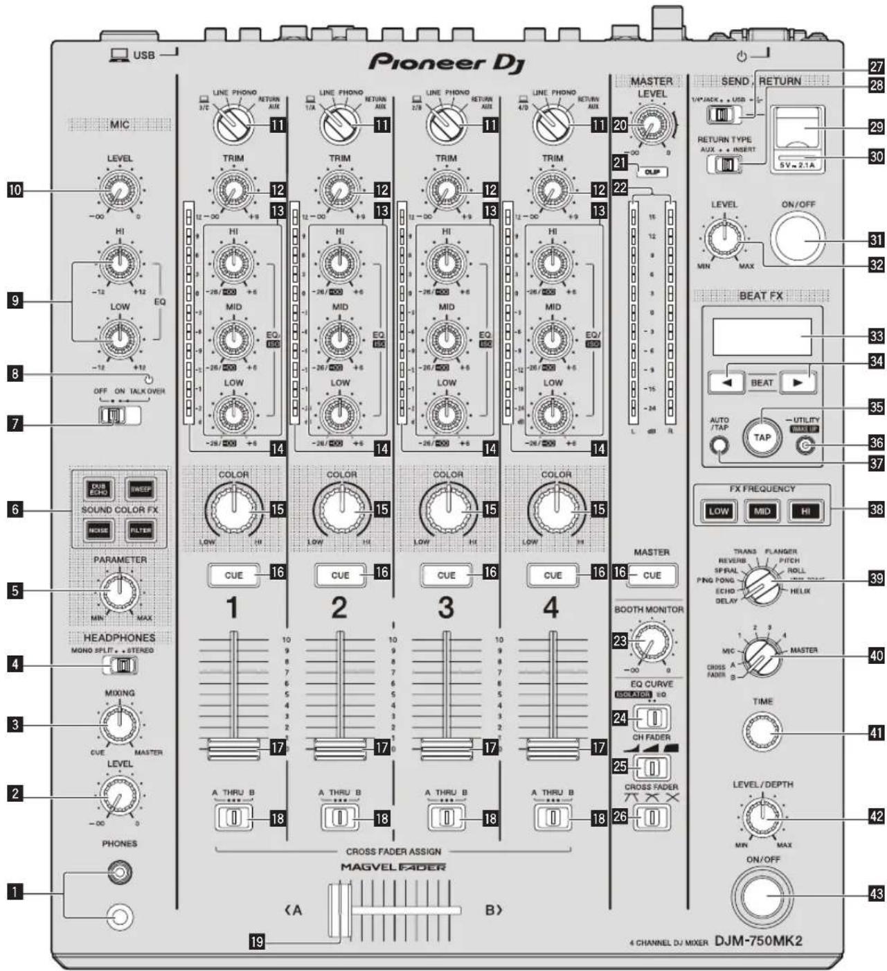
1 PHONES terminal (page 11)
Connect headphones.
1/4" stereo phone plugs and 3.5 mm stereo mini plugs are supported.
2 LEVEL control (page 11)
Adjusts the level of sound output from the headphones.
3 MIXING control (page 11)
Adjusts the monitor volume balance for the sound of the [MASTER] channel and the sound of the channel for which the [CUE] button is pressed.
4 MONO SPLIT, STEREO selector switch (page 11)
Sets the distribution of the monitor sound output from the headphones.
5 PARAMETER control
Adjusts the SOUND COLOR FX parameter.
6 SOUND COLOR FX buttons
Turns on and off SOUND COLOR FX.
7 OFF, ON, TALK OVER selector switch (page 11)
Turns the microphone on and off.
8 Microphone indicator (page 11)
9 EQ (HI, LOW) controls (page 11)
Adjusts the sound quality of the microphones.
10 MIC LEVEL control (page 11)
Adjusts the level of sound output from the microphone.
11 Input selector switches (page 11)
Selects the input source for each channel from the components connected to this unit.
12 TRIM control (page 11)
Adjusts the level of sound input to each channel.
13 EQ/ISO (HI, MID, LOW) controls (page 11)
Adjusts the sound quality of each channel.
14 Channel Level Indicator (page 11)
Displays the sound level of each channel before it passes through the channel faders.
15 COLOR control
This changes the parameters of the SOUND COLOR FX of the different channels.
16 CUE button (page 11)
Presses the [CUE] button of the channel to be monitored.
17 Channel Fader (page 11)
Adjusts the level of sound output from each channel.
18 CROSS FADER ASSIGN (A, THRU, B) selector switch (page11)
Sets the output destination of each channel to [A] or [B].
19 Crossfader(page11)
Outputs audio signals assigned by the crossfader assign switch corresponding to the curve characteristics selected by [CROSS FADER] (Crossfader Curve Selector Switch).
20 MASTER LEVEL control (page 11)
Adjusts the level of sound are output from the [MASTER1] and [MASTER2] terminals.
21 CLIP indicators
Master: Flashes when audio with an excessive volume level is output from the [MASTER1] or [MASTER2] terminals.
22 Master Level Indicator (page 11)
Displays the level of sound output from the [MASTER1] and [MASTER2] terminals.
23 BOOTH MONITOR control (page 11)
Adjusts the level of sound output from the [BOOTH] terminal.
24 EQ CURVE (ISOLATOR, EQ) selector switch (page 11)
Sets the function of the [EQ/ISO (HI, MID, LOW)] controls.
25 CH FADER ( ) select witch
Sets the curve characteristics of the channel fader.
26 CROSS FADER (7, ) selector switch
Sets the curve characteristics of the crossfader.
27 SEND/RETURN (1/4" JACK, • selector switch
Sets the input and output sources for the SEND/RETURN channel. You can select the device connected to the [SEND/RETURN] terminals on the rear panel of this unit or the device connected to the mobile device connection terminal on the operation panel.
28 RETURN TYPE (AUX, INSERT) selector switch
Sets the SEND/RETURN method.
29 Mobile device connection terminal (USB port)
Connect a mobile device.
30 USB connection indicator
Lights when a mobile device is connected. Blinks when an incompatible device is connected.
31 SEND/RETURN ON/OFF button
Turns SEND/RETURN on and off.
32 SEND/RETURN LEVEL control
Adjusts the sound level of SEND/RETURN.
33 Main display
Displays the effect name, BPM, effect parameter, etc.
34 BEAT ◀, ▶ buttons
Sets the beat fraction for synchronizing the effect sound.
35 TAP button
When the BPM measurement mode is set to [TAP], tap this button with a finger to input the BPM manually.
36 UTILITY (WAKE UP) button
— UTILITY: Press and hold down this button to display the [UTILITY] screen. It lights when the [UTILITY] screen is displayed. Press this button when the [UTILITY] screen is displayed to return to the normal screen.
— WAKE UP: Lights when the product enters standby mode. Press this button in standby mode to exit standby mode.
37 AUTO/TAP button
Sets the BPM measurement mode.
38 FX FREQUENCY button
Sets the range to apply BEAT FX. BEAT FX is applied to the lit button.
39 Beat effect selector switch
Sets the BEAT FX type.
40 Effect channel selector switch
Sets the channel to apply the BEAT FX and SEND/RETURN to.
41 TIME control
Adjusts the BEAT FX time parameter.
42 LEVEL/DEPTH control
Adjusts the BEAT FX quantitative parameter.
43 Beat effect ON/OFF button
Turns BEAT FX on and off.
Do not pull on the channel fader and crossfader knobs with excessive force. The knobs have a structure by which they cannot be pulled off easily. Pulling the knobs strongly may result in damaging the unit.
Connections
Turn off this unit and disconnect the power cord from the power outlet before connecting components or changing the connections.
Connect the power cord to a power outlet after all the connections are completed.
Be sure to use the power cord supplied with this unit.
Refer to the operating instructions for the components to be connected.
- When connecting this unit with a computer, be sure to use the USB cable supplied with this unit.
• A USB hub cannot be used.
Connecting input terminals

Connecting output terminals
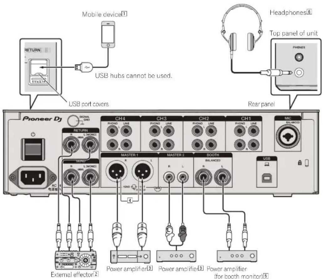
① When connecting a mobile device, use the cable supplied with the device.
For information on compatible mobile devices, see the Pioneer DJ site below. pioneerdj.com/support/
2 Also connect the external effector to the [RETURN] terminal (input terminal).
3 Be sure to use the [MASTER1] terminals for a balanced output. If it is connected to an unbalanced input (such as RCA) with an XLR to RCA converter cable (or converter adapter), etc., the sound quality may be lowered or noise may occur.
Use the [MASTER2] terminals for an unbalanced input (such as RCA).
4 Be careful not to accidentally insert the power cord of another unit to [MASTER1] terminal. Do not connect the terminal that can supply phantom power to the [MASTER1] terminal.
5 Be sure to use the [BOOTH] terminals for a balanced output. If they are connected to an unbalanced input (such as an RCA or TS input) with an TRS to RCA converter cable (or converter adapter), TS cable, etc., the sound quality may be lowered or noise may occur.
6 Connect headphones to either the phone jack or the mini jack. If both jacks are used at the same time, the sound quality and volume may be lowered.
Operation
Basic Operation
Outputting sound
1 Press the [⏻] button.
This unit turns on.
2 Set the input selector switches.
Select an input source for each channel from the components connected to this unit.
- [☐]: Selects the computer connected to the [USB] terminal as an input source.
- [LINE]: Selects the device connected to the [LINE] terminals as an input source.
- [PHONO]: Selects the analog player connected to the [PHONO] terminals as an input source.
• [RETURN AUX]: Selects the [SEND/RETURN] [RETURN] sound.
When using [RETURN AUX], selects [AUX] using the [SEND/RETURN] [RETURN TYPE].
When using [SEND/RETURN], see the Operating Instructions.
3 Turn the [TRIM] control.
Adjusts the level of sound input to each channel.
The channel level indicator lights when audio signals are properly input to the channel.
4 Move the channel fader up.
Adjusts the level of sound output from each channel.
5 Set the [CROSS FADER ASSIGN (A, THRU, B)] selector switch.
Set the output destination of each channel.
— [A]: Outputs to [A] (left) of the crossfader.
— [B]: Outputs to [B] (right) of the crossfader.
— [THRU]: Selects this when you do not want to use the crossfader. (The signals do not pass through the crossfader.)
6 Set the crossfader.
Skip this operation when the [CROSS FADER ASSIGN (A, THRU, B)] selector switch is set to [THRU].
7 Turn the [MASTER LEVEL] control.
Audio signals are output from the [MASTER1] and [MASTER2] terminals.
The master level indicator lights.
Adjusting the sound quality
1 Set the [EQ CURVE (ISOLATOR, EQ)] selector switch.
— [ISOLATOR]: Adjusts the isolator settings.
— [EQ]: Adjusts the equalizer settings.
2 Turn the [EQ/ISO (HI, MID, LOW)] controls for each channel.
The adjustable ranges for each control are as follows.
— [HI]: -26 dB to +6 dB (20 kHz)
— [MID]: -26 dB to +6 dB (1 kHz)
— [LOW]: -26 dB to +6 dB (20 Hz)
Monitoring sound with headphones
1 Connect headphones to the [PHONES] terminal.
2 Press the [CUE] button for the channel to monitor.
3 Set the [MONO SPLIT, STEREO] selector switch.
— [MONO SPLIT]: Outputs the sound of the channel selected with the [CUE] button to [L] and the sound of MASTER to R.
— [STEREO]: Outputs the sound of the channel for which the [CUE] button is pressed in stereo from the headphones.
4 Turn the [HEADPHONES MIXING] control.
Adjust the balance of the volume between the channel selected with the [CUE] button and MASTER.
5 Turn the [LEVEL] control for [HEADPHONES].
Adjust the volume of the headphones.
Using a microphone
1 Connect a microphone to the [MIC] terminal.
2 Set the [OFF, ON, TALK OVER] selector switch to [ON] or [TALK OVER].
- When set to [TALK OVER], the sound of channels other than the [MIC] channel is attenuated by 18 dB (default) if a sound of -10 dB or greater is input to the microphone.
- The sound attenuation level of [TALK OVER] can be set in [UTILITY]. For details, see the Operating Instructions.
- The TALK OVER mode has a normal mode and an advanced mode (default), and those modes can be switched. For details, see the Operating Instructions.
3 Turn the [MIC LEVEL] control to adjust the audio level of the microphone.
Adjust the level of sound output from the [MIC] channel.
- Note that the sound is output at a loud volume if the control is rotated to the extreme right.
4 Input audio to the microphone.
Outputting sound from the [BOOTH] terminals
Turn the [BOOTH MONITOR] control.
Adjusts the level of sound output from the [BOOTH] terminal.
Changing the settings
- For details on how to change the settings of this unit, refer to "Changing the settings" in the Operating Instructions.
Additional information
Troubleshooting
- If something is wrong with this unit, check the following issues, and also access the Pioneer DJ site and check [FAQ] for [DJM-750MK2]. pioneerdj.com/support/
Sometimes the problem may lie in another component. Inspect the other components and electrical appliances being used. If the problem cannot be rectified, ask your nearest service center or your dealer to carry out repair work. - This unit may not operate properly due to static electricity or other external influences. In such cases, disconnect the power cord and connect it again to restore normal operation.
Problem Check Remedy
| Sound is not output, or sound is too small. | Is the input selector switch set to the proper position? | Change the input source for the channel using the input selector switch. (page11) |
| Are the connection cables properly connected? Connect the connection cables properly. (page 9) | ||
| Are the terminals and plugs dirty? Clean the terminals and plugs before connecting them to the unit. | ||
| Is [MASTER ATT.] set to [-6 dB], etc.? | Switch [MASTER ATT.] in the [UTILITY] screen. | |
| Sound is distorted. | Is the level of sound output from the [MASTER] channel appropriately set? | Adjust the [MASTER LEVEL] control so that the master channel level indicator lights around [0 dB] at the peak level. (page 11) |
| Is the level of audio input to each channel properly set? | Adjust the [TRIM] control so that the channel level indicator lights at about [0 dB] at the peak level. (page 11) | |
| The crossfade function does not work. | Are the [CROSS FADER ASSIGN (A. THRU, B)] selector switches properly set? | Set the [CROSS FADER ASSIGN (A. THRU, B)] selector switches for the different channels properly. (page 11) |
| Sound is distorted when an analog player is connected to the [PHONO] terminals.Or, lighting of the channel level indicator does not change when the [TRIM] control is turned. | Is an analog player with a built-in phono equalizer connected to this unit? | Connect the analog player with built-in phono equalizer to the [LINE] terminals. (page9) |
| Set the PHONO/LINE selector switch on the analog player to PHONO if available. | ||
| Is an audio interface for computers connected between the analog player and this unit? | If the output of the audio interface for computers is line level, connect it to the [LINE] terminals. (page 9) | |
| Set the PHONO/LINE selector switch on the analog player to PHONO if available. | ||
Trademarks and registered trademarks
- "Pioneer DJ" is a trademark of PIONEER CORPORATION, and is used under license.
- rekordbox is a trademark or registered trademark of the Pioneer DJ Corporation.
The names of companies and products mentioned herein are trademarks or registered trademarks of their respective owners.
Cautions on copyrights
rekordbox restricts playback and duplication of copyright-protected music contents.
- When coded data, etc., for protecting the copyright is embedded in the music contents, it may not be possible to operate the program normally.
- When rekordbox detects that coded data, etc., for protecting the copyright is embedded in the music contents, processing (playback, reading, etc.) may stop.
Recordings you have made are for your personal enjoyment and according to copyright laws may not be used without the consent of the copyright holder.
- Music recorded from CDs, etc., is protected by the copyright laws of individual countries and by international treaties. It is the full responsibility of the person who has recorded the music to ensure that it is used legally.
- When handling music downloaded from the Internet, etc., it is the full responsibility of the person who has downloaded the music to ensure that it is used in accordance with the contract concluded with the download site.
Specifications
General – Main Unit
Power requirements ......AC 110 V to 240 V, 50 Hz/60 Hz
Power consumption....40 W
Power consumption (standby) 0.3 W
Main unit weight 6.6 kg
Max. external dimensions ...320 mm (W) × 107.9 mm (H) × 387.9 mm (D)
Tolerable operating temperature ....+5 °C to +35 °C
Tolerable operating humidity 5% to 85% (no condensation)
Audio Section
Sampling rate....48 kHz
D/A converter 32-bit
Channel input A/D converter 32-bit
Other A/D converter 24-bit
Frequency characteristic LINE 20 Hz to 20 kHz
S/N ratio (rated output)
PHONO 87 dB
LINE 105 dB
MIC 79 dB
Total harmonic distortion (LINE — MASTER1)....0.005 %
Standard input level / Input impedance
PHONO....-52 dBu/47 kΩ
LINE -12 dBu/47 kΩ
MIC -57 dBu/3 kΩ
RETURN -12 dBu/47 kΩ
Standard output level / Load impedance / Output impedance
MASTER1....+6 dBu/10 kΩ/300 Ω
MASTER2....+ 2 dBu/10 kΩ/680 Ω
BOOTH + 6 dBu/10 kΩ/300 Ω
SEND (when RETURN TYPE is "AUX")....-6 dBu/10 kΩ/680 Ω
SEND (when RETURN TYPE is "INSERT")......-12 dBu/10 kΩ/680 Ω
PHONES + 8 dBu/32 Ω/10 Ω or less
Rated output level / Load impedance
MASTER1 +25 dBu/10 kΩ
MASTER2....+21 dBu/10 kΩ
Crosstalk (LINE) 82 dB
Channel equalizer characteristic
HI -26 dB to +6 dB (20 kHz)
MID....-26 dB to +6 dB (1 kHz)
LOW -26 dB to +6 dB (20 Hz)
Microphone equalizer characteristic
HI -12 dB to +12 dB (10 kHz)
LOW -12 dB to +12 dB (100 Hz)
Input / Output terminals
PHONO input terminal RCA pin jacks....4 sets
LINE input terminal RCA pin jacks....4 sets
MIC input terminal (XLR/TRS) XLR connector & 1/4" TRS jack ....1 set
RETURN Input terminals (TS) 1/4" TS jack....1 set
MASTER output terminal XLR connector....1 set RCA pin jacks....1 set
BOOTH output terminal 1/4" TRS jack....1 set
SEND output terminal (TS) 1/4" TS jack....1 set
PHONES output terminal 1/4" stereo phone jack....1 set 3.5 mm stereo mini jack....1 set
USB terminal Type A....1 set Power supply...5 V/2.1 A or less B type....1 set
- The specifications and design of this product are subject to change without notice.
• © 2017 Pioneer DJ Corporation. All rights reserved.

42 Commande LEVEL/DEPTH
Consommation....40 W
42 Controllo LEVEL/DEPTH
MID.....Da-26 dB a +6 dB (1 kHz)
LOW Da -26 dB a +6 dB (20 Hz)
HI Da-12 dB a+12 dB (10 kHz)
LOW Da-12 dB a+12 dB (100 Hz)
WAARSCHUWING NETSNOER
Specifications....12
Alvorens te beginnen
Kenmerken
42 LEVEL/DEPTH instelling
2 Stel de [OFF, ON, TALK OVER] keuzeschakelaar in op [ON] of [TALK OVER].
42 Control LEVEL/DEPTH
General – Unidad principal
Requisitos de potencia....CA 110 V a 240 V, 50 Hz/60 Hz
MID....-26 dB a + 6 dB (1 kHz)
LOW -26 dB a +6 dB (20 Hz)
Em especial, leia as "INSTRUÇÕES DE SEGURANÇA IMPORTANTES".
7 Interruptor seletor OFF, ON, TALK OVER (página 10)
27 Interruptor seletor SEND/RETURN (1/4" JACK,

Outro conversor A/D 24-bit
MID....-26 dB a +6 dB (1 kHz)
LOW -26 dB a +6 dB (20 Hz)
© 2017 Pioneer DJ Corporation. All rights reserved.
Pioneer DJ Corporation
6F, Yokohama i-Mark Place, 4-4-5 Minatomirai, Nishi-ku, Yokohama, Kanagawa 220-0012 JAPAN
Pioneer DJ 株式会社
Pioneer DJ Europe Limited
Anteros Building, Odyssey Business Park, West End Road, South Ruislip, Middlesex, HA4
6QQ, U.K. TEL: +44-203-7617-220
Pioneer DJ Americas, Inc.
2050 W. 190th Street, Suite 109, Torrance, CA 90504, U.S.A. TEL: +1 (424) 488-0480
PIONEER ELECTRONICS ASIACENTRE PTE. LTD.
2 Jalan Kilang Barat, #07-01, Singapore 159346 TEL: +65-6378-7888
PIONEER ELECTRONICS AUSTRALIA PTY. LTD.
5 Arco Lane, Heatherton, Victoria, 3202, Australia, TEL: +61-3-9586-6300
PIONEER ELECTRONICS (THAILAND) CO., LTD.
17th Fl., KPN Tower, 719 Rama 9 Road, Bangkapi, Huaykwang, Bangkok 10310
TEL: +66-2-717-0777
PIONEER TECHNOLOGY (MALAYSIA) SDN. BHD
16th Floor, Menara Uni. Asia 1008 Jalan Sultan Ismail 50250 Kuala Lumpur
TEL: +60-3-2697-2920
先鋒股份有限公司
PIONEER INDIA ELECTRONICS PRIVATE LTD.
216, Second Floor, Time Tower, M.G. Road, Sector 28, Gurgaon 122001,
Haryana, India TEL: +91-124-463-6100
PDJ_001_all
Сделано в Малайзии


- CAUTION
- WARNING
- For Finland customers
- For Norway customers
- For Sweden customers
- For Denmark customers
- Operating Environment
- VENTILATION CAUTION
- POWER-CORD CAUTION
- Contents
- How to read this manual
- Before start
- Part names and functions
- Connections
- Operation
- Additional information
- Before start
- Features
- Accessories
- Cautions
- Obtaining the Operating Instructions
- Part names and functions
- PHONES terminal (page 11)
- LEVEL control (page 11)
- MIXING control (page 11)
- MONO SPLIT, STEREO selector switch (page 11)
- PARAMETER control
- SOUND COLOR FX buttons
- OFF, ON, TALK OVER selector switch (page 11)
- Microphone indicator (page 11)
- EQ (HI, LOW) controls (page 11)
- MIC LEVEL control (page 11)
- Input selector switches (page 11)
- TRIM control (page 11)
- Connections
- Connecting input terminals
- Connecting output terminals
- Operation
- Basic Operation
- Outputting sound
- Press the [⏻] button.
- Set the input selector switches.
- Turn the [TRIM] control.
- Move the channel fader up.
- Set the [CROSS FADER ASSIGN (A, THRU, B)] selector switch.
- Set the crossfader.
- Turn the [MASTER LEVEL] control.
- Adjusting the sound quality
- Set the [EQ CURVE (ISOLATOR, EQ)] selector switch.
- Turn the [EQ/ISO (HI, MID, LOW)] controls for each channel.
- Monitoring sound with headphones
- Connect headphones to the [PHONES] terminal.
- Press the [CUE] button for the channel to monitor.
- Set the [MONO SPLIT, STEREO] selector switch.
- Turn the [HEADPHONES MIXING] control.
- Turn the [LEVEL] control for [HEADPHONES].
- Using a microphone
- Connect a microphone to the [MIC] terminal.
- Set the [OFF, ON, TALK OVER] selector switch to [ON] or [TALK OVER].
- Turn the [MIC LEVEL] control to adjust the audio level of the microphone.
- Input audio to the microphone.
- Outputting sound from the [BOOTH] terminals
- Changing the settings
- Additional information
- Troubleshooting
- Trademarks and registered trademarks
- Cautions on copyrights
- Specifications
- General – Main Unit
- Audio Section
- Input / Output terminals
- WAARSCHUWING NETSNOER
- Alvorens te beginnen
- Kenmerken
- Stel de [OFF, ON, TALK OVER] keuzeschakelaar in op [ON] of [TALK OVER].
- General – Unidad principal
- Interruptor seletor OFF, ON, TALK OVER (página 10)
- Pioneer DJ Corporation
- Pioneer DJ 株式会社
- Pioneer DJ Europe Limited
- Pioneer DJ Americas, Inc.
- PIONEER ELECTRONICS ASIACENTRE PTE. LTD.
- PIONEER ELECTRONICS AUSTRALIA PTY. LTD.
- PIONEER ELECTRONICS (THAILAND) CO., LTD.
- PIONEER TECHNOLOGY (MALAYSIA) SDN. BHD
- 先鋒股份有限公司
- PIONEER INDIA ELECTRONICS PRIVATE LTD.
Brand : PIONEER
Model : DJM750MK2
Category : DJ Equipment