
UKV 201000 - Boiler Nibe - Free user manual and instructions
Find the device manual for free UKV 201000 Nibe in PDF.

| Product type | Buffer tank for heating system |
| Brand | Nibe |
| Model | UKV 201000 |
| Capacity | 39 liters |
| Net weight | 16 kg |
| Maximum working pressure | 6 bar (0.6 MPa) |
| Operating temperature | +4 °C to +95 °C |
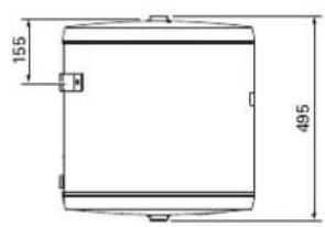
| Dimensions (diameter × height) | 450 mm × 495 mm |
| Hydraulic connections | G1" internal (heating circuit outlet XL1, heat pump inlet XL8) |
| Tank material | Insulated steel (anti-condensation) |
| Insulation | Polyurethane |
| External coating | White powder-coated sheet metal with durable plastic ends |
| Main functions | Volume and flow increase, temperature peak reduction, external heating control |
| Installation | Vertical wall mounting, bracket supplied |
| Maintenance | Check safety valve 4 times per year; replace if defective |
| Safety | Safety valve ≤6 bar; installed by qualified professional |
| Spare parts | Use only genuine NIBE parts |
| Serial number | 14 digits, located on the label (PZ3) |
| General information | Manufactured according to Directive 2014/68/EU; energy efficiency class B |
Frequently Asked Questions - UKV 201000 Nibe
User questions about UKV 201000 Nibe
0 question about this device. Answer the ones you know or ask your own.
Ask a new question about this device
Download the instructions for your Boiler in PDF format for free! Find your manual UKV 201000 - Nibe and take your electronic device back in hand. On this page are published all the documents necessary for the use of your device. UKV 201000 by Nibe.
USER MANUAL UKV 201000 Nibe
natural_image
White cylindrical industrial vessel with a black bolt, labeled 'NIBE UKV' on the side (no other text or symbols visible)
natural_image
Icon of a wrench and hand inside a hexagon, symbolizing tools or maintenance (no text or symbols)Table of Contents
Svenska
4Viktig information
6Till användaren
7Till installatören
This manual describes installation and service procedures for implementation by specialists.
The manual must be left with the customer.
This appliance can be used by children aged from 8 years and above and persons with reduced physical, sensory or mental capabilities or lack of experience and knowledge if they have been given supervision or instruction concerning use of the appliance in a safe way and understand the hazards involved. Children shall not play with the appliance. Cleaning an user maintenance shall not be made by children without supervision.
This is an original manual. It may not be translated without the approval of NIBE. Rights to make any design or technical modifications are reserved.
©NIBE 2023.
SERIAL NUMBER
The serial number can be found on top of the product.

Caution
Always give the product's serial number when reporting a fault.
RECOVERY
Leave the disposal of the packaging to the installer who installed the product or to special waste stations.
Do not dispose of used products with normal
se household waste. It must be disposed of at a special waste nderation or dealer who provides this type of service.
Improper disposal of the product by the user results in ad- ministrative penalties in accordance with current legislation.
SYMBOLS
Explanation of symbols that may be present in this manual.

NOTE
This symbol indicates danger to person or machine.

Caution
This symbol indicates important information about what you should consider when installing or servicing the installation.
MARKING
Explanation of symbols that may be present on the product's label(s).
GENERAL
UKV 40 is designed and manufactured according to sound engineering practice in order to ensure safe usage.
INSPECTION OF THE INSTALLATION
Current regulations require the heating installation to be inspected before it is commissioned. The inspection must be carried out by a suitably qualified person.
| √ | DateSignatu | |||
| Heating medium (page 14) | ||||
| Shut o valves | ||||
| Safety valve | ||||
For the User
MAINTENANCE
The safety valve in the system where the accumulator tank is installed must be inspected regularly (about four times a year) to prevent blockages.
To inspect the valve, open the safety valve manually and check that water ows through the overow pipe. If this does not happen then the safety valve is defective and must be replaced.
SERVICE
For service, contact the installer. Serial number (PZ3) (14 digits) and installation date should always be stated.
Only replacement parts supplied by NIBE may be used.
For the Installer
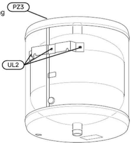
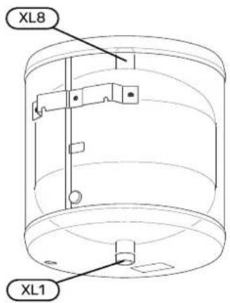
COMPONENT LOCATION
UKV 40
GENERAL
UKV 40 has several dierent areas of use.
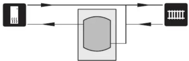
UKV 40 can be used during external control of the heating system. The heat pump then charges UKV 40 with oating or xed condensing. The external control function controls the heat distribution from UKV 40 to the consumer.
If the ow to the heating system can be restricted using radiator thermostats, for example, install a UKV 40 as an intermediate tank. This ensures a secure ow for the heat pump.
UKV 40 also allows a greater ow to the heating system than across the heat pump.
In some installations, so-called heating clicks occur as a result of movements during changes in temperature. To eliminate temporary changes in temperature, and thereby prevent heating clicks, install a UKV 40 after the heating installation.
UKV 40 can also be used to increase the system volume thereby prevent malfunctions.
The accumulator tank consists of a condensation-insulated steel vessel with polyurethane insulation. Outer cladding white, powder-coated sheet metal with ends of durable plastic.
The accumulator tank is designed and manufactured for a maximum cut-o pressure of 6 bar.
The working temperature is +4 to +95 °C.
| andtion | NameDesigna- |
| d | Holes for wall bracketUL2 |
| in | Serial number platePZ3 |
TRANSPORT
UKV 40 should be transported and stored in the dry.
ASSEMBLY
The accumulator tank must be installed in a dry area at a temperature that does not drop below 0 °C (frost-free).
MOUNTING
UKV 40 has to be installed vertically suspended on the wall. First install the enclosed mounting bracket on the wall, then suspend UKV 40 from the bracket.
SUPPLIED COMPONENTS
Suspension bracket.
INSTALLATION
All connections (including connections or holes that are used) must be insulated to minimise energy losses.
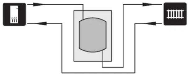
DOCKINGS

NOTE
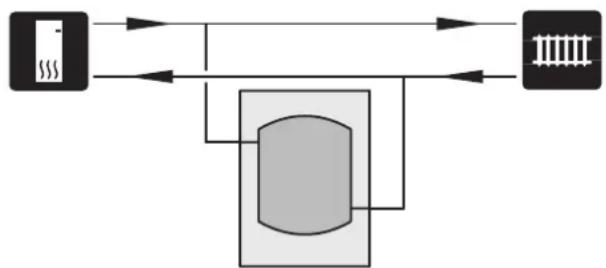
These are outline diagrams. Actual installations must be planned according to applicable standards.
Volume increase as well as reduction of spikes
flowchart
graph TD
    A["Device"] --> B["Processing Unit"]
    B --> C["Output Module"]
    B --> D["Storage Unit"]
    D --> B
    B --> E["Data Bus"]
    E --> A
A UKV 40 is installed as a volume increaser in those cases vent the accumulator tank by loosening the connection where the system volume in the climate system is below (XL8) at the top of the accumulator tank. the minimum recommended volume for the heat pump. 2. Fill the vessel through the drain valve.
Volume and ow increaser and reduction in heat spikes
flowchart
graph TD
    A["Server"] --> B["Processing Unit"]
    B --> C["Output Module"]
    A -->|Data Flow| B
    B -->|Data Flow| C
A UKV 40 is installed as a volume and ow increaser in those cases where the system volume in the climate system is below the minimum recommended volume for the heat pump and/or the ow is restricted without control.
Volume increase as well as reduction of heat spikes
flowchart
graph LR
    A["Device"] --> B["Processing Unit"]
    B --> C["Output Module"]
    B --> D["Storage Unit"]
    style A fill:#f9f,stroke:#333
    style B fill:#ccf,stroke:#333
    style C fill:#cfc,stroke:#333
    style D fill:#fcc,stroke:#333
A UKV 40 is installed as a volume increaser in those cases where the system volume in the climate system is below the minimum recommended volume for the heat pump.
PIPE INSTALLATION
Pipe installation must be carried out in accordance with current norms and directives.
The drain valve is installed on the heating system's supply line (XL1).
The system where UKV 40 is installed must be supplied with a safety valve of max. 6 bar (0.6 MPa).
The overow pipe must be the same size as the safety valve's. Route the overow pipe from the safety valve, sloping along its entire length, and ensure that it is frost- eat of and well supported. The mouth of the overow pipe must be visible and not placed close to electrical components.
Ensure that incoming water is clean.
If uncertain, contact a plumber alternatively see applicable standards.
FILLING
Fill the accumulator tank as follows:
-
Fill the vessel through the drain valve.
-
When only water comes out of the connection (XL8) (an air-water mixture emerges initially), the connection can be closed and the accumulator tank is lled.
Technical data
DIMENSIONS
UKV 40
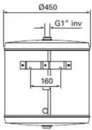
PIPE CONNECTIONS
UKV 40
TECHNICAL SPECIFICATIONS
| UKV 401 | ||
| 39litreVolume | ||
| 16kgNet weight | ||
| 0.6 / 6MPa/barMax | ||
| +4 - +95°CMax. opε | ||
| Part No. | 088 470 |
ENERGY LABELLING
| Supplier | NIBE | |
| Model | UKV-40 | |
| Eciency class 1 | B | |
| Heat loss | W | 28 |
| Volume | I | 39 |
1 Scale for the product's eciency class A+ to F.
PIPE DIMENSIONS
| Connection | ||
| G1" int.Supply line, heating systemXL1 | ||
| G1" int.Docking from heat pumpXL8 | ||