
infrabox IRBS - Remote control HARVIA - Free user manual and instructions
Find the device manual for free infrabox IRBS HARVIA in PDF.
| Product type | Remote control for infrared cabin |
| Brand | Harvia |
| Model | Infrabox IRBS |
| Control panel dimensions | 163 x 104 x 38 mm |
| Power block dimensions | 195 x 119 x 48 mm |
| Mounting cut-out | 48 x 60 mm |
| Power supply | 230 V AC / 50 Hz, max 16 A |
| Max heating power (switching) | 3.5 kW |
| Max power in half-wave control | 1.3 kW |
| Max power in phase control | 350 W |
| Lighting/fan power | 100 W |
| Main functions | Switching, 5-level dimming, on/off timer, I/O/I timer, seat sensor (optional), remote activation, enable input, heating time limitation (6 h, 12 h, 18 h, 24 h) |
| Safety | Automatic shutdown after maximum time, LED error messages, possibility to connect a safety temperature limiter |
| Protection degree | IP4 (water jets) |
| Permissible ambient temperature | -10 °C to +40 °C (power block); -10 °C to +110 °C (control panel) |
| Max. air humidity | 95 % (power block); 99 % RH without condensation (control panel) |
| Maintenance | Cleaning with a damp cloth and mild soap; no special maintenance |
| Repairability | Contact customer service for defects; no spare parts listed |
| Optional accessories | Film sensor WC4-IRF-F, seat sensor, infrared emitter socket, Swiss connection line, fan for IR cabin |
| General information | Manual available in several languages; download at www.sentiotec.com/downloads |
Frequently Asked Questions - infrabox IRBS HARVIA
User questions about infrabox IRBS HARVIA
0 question about this device. Answer the ones you know or ask your own.
Ask a new question about this device
Download the instructions for your Remote control in PDF format for free! Find your manual infrabox IRBS - HARVIA and take your electronic device back in hand. On this page are published all the documents necessary for the use of your device. infrabox IRBS by HARVIA.
USER MANUAL infrabox IRBS HARVIA
Infrared control unit
infrabox
INSTRUCTIONS FOR INSTALLATION AND USE English
Infrabox Set 1-035-704 / IRB-S
Infrabox white Set 1-039-846 / IRB-S-W
Table of Contents
1. About this instruction manual 4
2. Important information for your safety 5
2.1. Intended use 5
2.2. Safety information for the installer 7
3. Product description 8
3.1. Scope of delivery 8
3.2. Optional accessories 8
3.3. Product functions 8
4. Installation 10
4.1. Installing the power supply unit 10
4.2. Installing the control unit 11
4.3. Installing the foil temperature sensor 13
5. Electrical connection 14
5.1. Connection area for sensor/control unit 14
5.2. Connection diagram for 230 V 15
5.3. Connecting the light / fan 16
5.4. Connecting the seat sensor (optional) 16
5.5. Connecting the foil sensor (optional) 16
5.6. Connecting the HV input (remote start/enable input) 16
5.7. Connecting the safety temperature limiter (optional) 17
5.8. Connecting the infrared heater / infrared plate 17
6. Starting up 18
6.1. Operating mode 19
6.2. Operating type (infrared heater/infrared plate) 20
6.3. Operating time 21
6.4. Foil sensor 22
6.5. Seat time (optional for seat sensor) 23
6.6. On-time (I/O and I/O/I) 24
6.7. Out-time (I/0/I) 26
6.8. Leading/trailing edge phase control 29
6.9. HV input (remote start/enable input) 29
7. Performing tests 30
8. Safety information for the user 31
9. Operation 32
9.1. Description of control elements 32
9.2. Switching the infrared controller 33
9.3. Activating the dimming function for the light/fan 33
9.4. Dimming function for infrared heater/infrared plate 34
9.5. Standby for remote operation 35
9.6. Seat sensor (optional) 35
10. Cleaning and maintenance
10.1. Cleaning 36
10.2. Maintenance 36
11. Disposal
12. Troubleshooting 37
12.1. Error messages 37
13. Technical data
1. About this instruction manual
Read these installation and operating instructions carefully and keep them within reach when using the infrared control unit. This ensures that you can refer to information about your safety and the operation at any time.
These installation and operating instructions can also be found in the downloads section of our website: www.sentiotec.com/downloads.
Symbols used for warning notices
In these instructions for installation and use, a warning notice located next to an activity indicates that this activity poses a risk. Always observe the warning notices. This prevents damage to property and injuries, which in the worst case may be fatal.
The warning notices contain keywords, which have the following meanings:
DANGER!
Serious or fatal injury will occur if this warning notice is not observed.
WARNING!
Serious or fatal injury can occur if this warning notice is not observed.
CAUTION!
Minor injuries can occur if this warning notice is not observed.
ATTENTION!
This keyword is a warning that damage to property can occur.
Other symbols
This symbol indicates tips and useful information.

Do not cover Read the operating instructions

2. Important information for your safety
The infrared controller has been produced in accordance with the safety regulations applicable for technical units. However, hazards may occur during use. Therefore adhere to the following safety information and the specific warning notices in the individual chapters. Also observe the safety information for the devices connected.
2.1. Intended use
The Infrabox infra controller is used exclusively for controlling and operating the light/fan and infrared heater/infrared plate.

The Infrabox infrared controller is only suitable for use with intrinsically safe infrared heaters and infrared plates. If no intrinsically safe products are being used, a safety temperature limiter must be connected.
Observe the instructions for this in the operating instruction manual. The infrared controller may only be used for controlling a maximum capacity of 3.5 kW.
Overview of the operating modes:
Switchable: up to 3.5 kW
Half-wave control (dimmable): up to 1.3 kW
Leading edge phase control (dimmable): up to 350 W
Suitable infrared heaters: DIR-350-R, WIR-350-R, DIR-500-R, WIR-500-R, DIR-750-R, WIR-750-R, DIR-1300-R, WIR-1300-R, ECO-350-R, ECO-350-G, ECO-500-R, ECO-500-G, ECO-750-R, O-IRC-W
Suitable infrared plates: IR-WP-175, IR-WP-100, IR-WP-390, IR-WP-510, IR-WPHL-510, IR-WPHL-100, IR-WPHL-390, IR-WPHL-175
ATTENTION!
Only use infrared plates in connection with the optional WC4-IRF-F foil sensors.
- Before using the controller for the first time, check that the cabin is ready to operate. Particularly if the controller is switched on by remotely.
- Only the mains connection cable provided or the optional one for Switzerland (IR-CP-CH) may be used.
- The power supply unit may only be installed and operated together with the control unit provided.
Any use exceeding this scope is considered improper use. Improper use can result in damage to the product, in severe injuries or death.
2.2. Safety information for the installer
- The clamping connections may only be installed by a qualified electrician or similarly qualified person.
-
The plugs connectors may be installed by the user.
-
Installation and connection of the infrared control unit may only be performed when the power supply is disconnected.
- Also comply with the regulations applicable at the installation location.
- Before the infrared controller is switched on, make sure that no flammable objects have been hung over the infrared heater or on the infrared plate.
- For your own safety, consult your supplier in the event of problems that are not described in sufficient detail in the installation and operating instructions.
3. Product description
3.1. Scope of delivery
- Infrabox controller
• Infrabox power supply unit - Power supply unit connection cable 2.5 m (item no.: IR-CP-EH)
- Installation material
• Installation instruction manual - Light plug
- HV plug
3.2. Optional accessories
- Foil sensor (WC4-IRF-F) incl. 5 m connection cable
- Seating sennor (IRB-F-S) incl. 1 m connection cable
- Infrared heater plug (item no.: WC4-P-RA)
- Infrared mains connection cable 2.5 m, Switzerland (item no.: IR-CP-CH)
- Fan for IR cabins incl. cable and plug (WC4-IRX-FAN)
3.3. Product functions
The Infrabox infrared controller features the following functions:
- Switching the infrared heater or infrared plate with a heating capacity of max. 3.5 kW
- Controlling (dim) the infrared controller in 5 levels with the half-wave control unit (up to 1.3 kW)
-
Controlling (dim) the infrared controller in 5 levels with the leading edge phase control (up to 350 W)
-
Remote start function
- Seating sensor function (optional accessories)
- Controlling (dim) the light or fan in 5 levels
- Timer function
The Infrabox infrared controller is suitable for use with intrinsically safe infrared heaters and infrared plates. If no intrinsically safe products are being used, a safety temperature limiter must be connected.
- If infrared heaters are connected, they must have a safety temperature limiter. For suitable infrared heaters see 2.1. Intended use on page 5.
- If infrared plates are connected, the WC4-IRF-F foil sensors must be used and activated (see 4.3. Installing the foil temperature sensor on page 13 and 5.5. Connecting the foil sensor (optional) on page 16). For suitable infrared plates see 2.1. Intended use on page 5.
- Automatic heating period limiter The infrared controller shuts down automatically after the maximum heating period for safety reasons (see also 6.3. Operating time on page 21).

The EN 60335-2-53 specifies a maximum heating period limit of 6 hours for private infrared cabins. For infrared cabins in hotels, apartment blocks and similar locations, a maximum heating period limit of 12 hours is permissible. Extending the heating period limit to 18 hours or 24 hours is only permitted in public infrared cabins.
4. Installation
4.1. Installing the power supply unit
The power supply unit is installed on the cabin roof (Fig.1), on the cabin wall or in another suitable location in accordance with the ambient conditions. The power is supplied with a mains connection cable and safety plug.
ATTENTION!
Damage to the unit
- Install the power supply unit in a dry place. Maintain a maximum ambient temperature of 40 °C and a maximum humidity of 95%.
- A free circulation of air must be ensured to cool the power supply unit. The power supply unit must not be covered by any objects or materials.
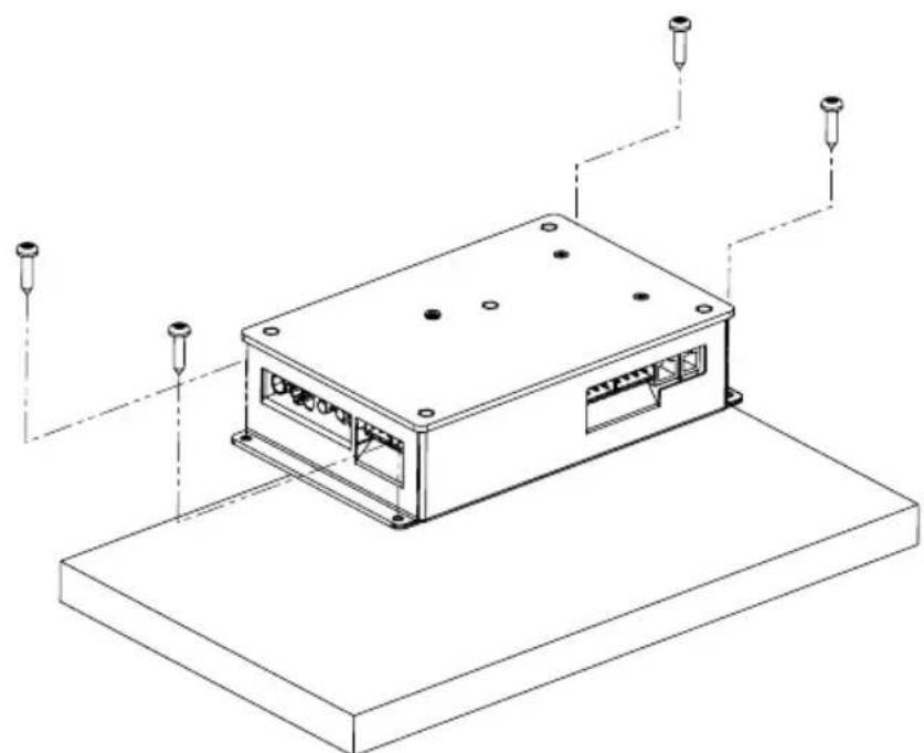
Fig. 1 Installing the power supply unit
- Screw the Infrabox power supply unit housing to the cabin ceiling or the cabin wall with the four wooden screws provided (16 mm long).
4.2. Installing the control unit
The control unit 2 of the infrared controller is installed on the outside wall of the cabin with a maximum clearance of 10 metres from the power supply unit 1 (see Fig. 2). For the installation, a standard jigsaw is required to cut out the recess for the control unit. The control unit can be installed both inside and outside the cabin.
* For installing inside an infrared cabin, a minimum clearance of 30 cm must be maintained (see Fig. 2 Control unit position on page 11).
ATTENTION!
Damage to the unit
- The control unit 2 of the infrared controller is splashproof (protection class IP X4).
- Work on the control unit must only be carried out using a standard screwdriver. Using a cordless screwdriver may cause irreparable damage to the housing.
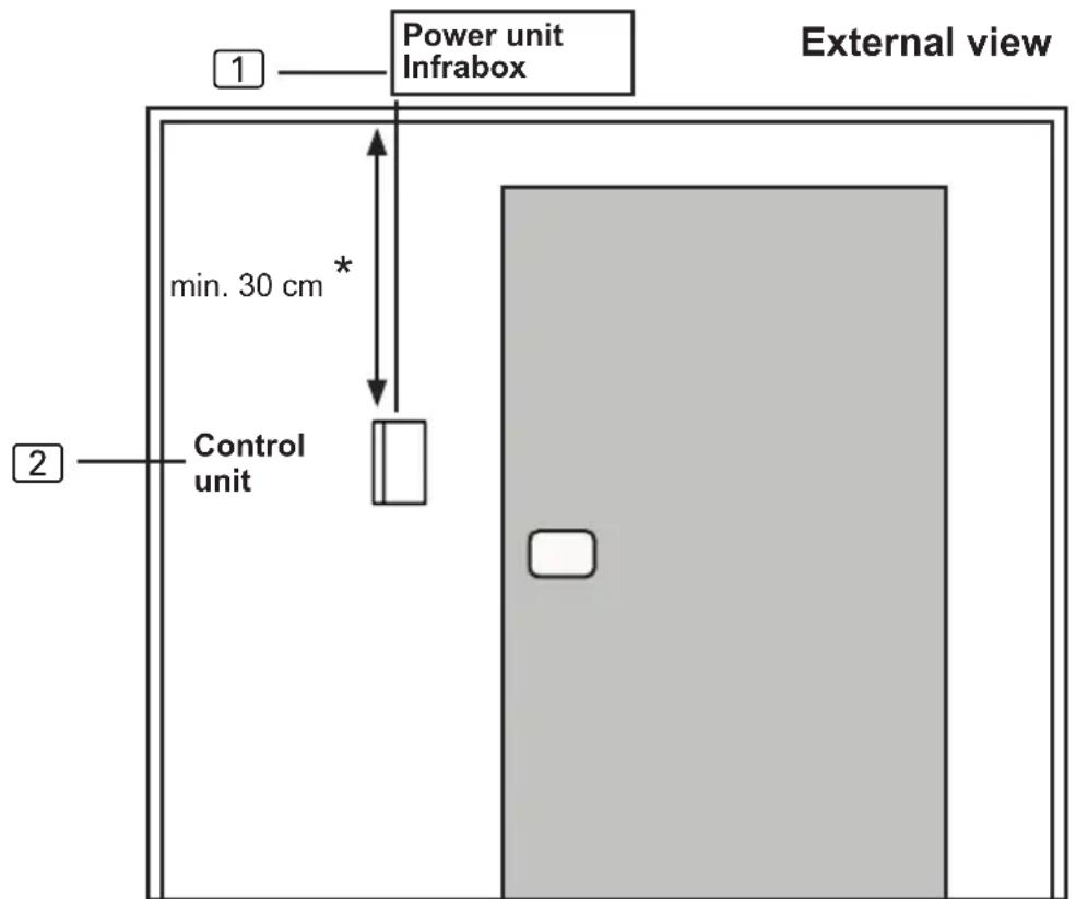
Fig. 2 Control unit position
* for assembly inside the cabin
- Cut out the 60 x 48 mm recess using a jigsaw, for example.
- Provide cable guides for the connecting cables.
- Screw the housing to the cabin wall through the hole with the 4 wood screws enclosed.
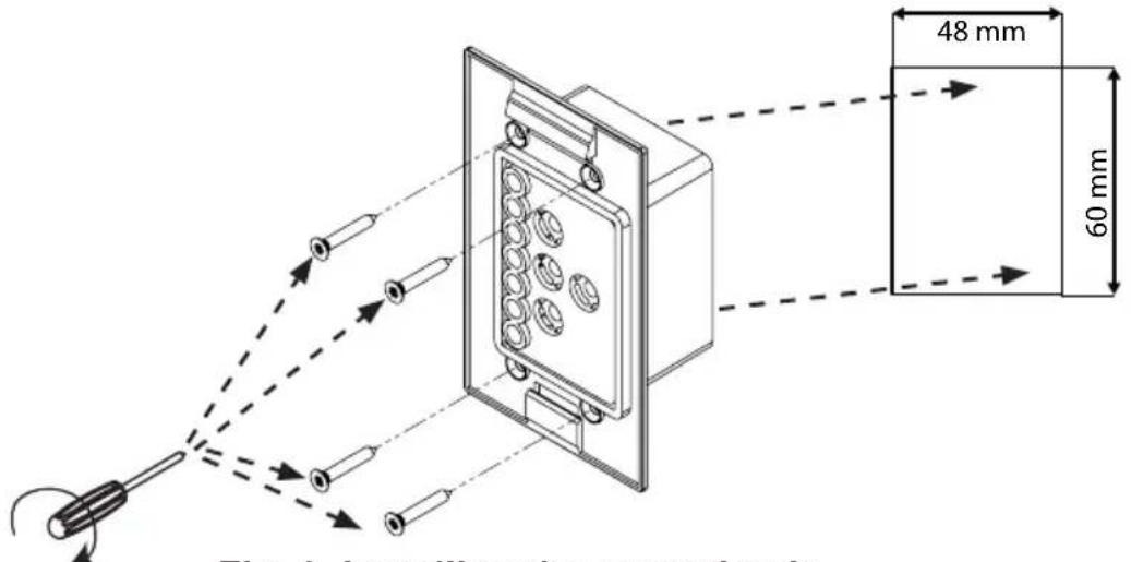
Fig. 3 Installing the control unit
- The front panel of the control unit is inserted with slight pressure into the housing. Ensure that the lower catch engage noticeably.
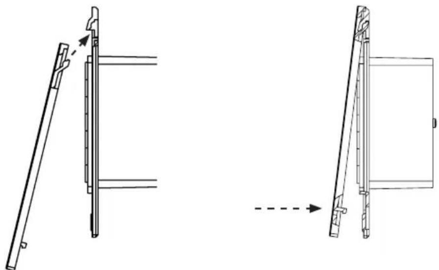
Fig. 4 Installing the control unit
- Connect the 4-pin connector with the RJ11 socket on the control unit.
4.3. Installing the foil temperature sensor
The foil temperature sensor is only required for infrared plate heating systems. Observe the details of the plate heating system manufacturer here.
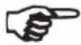
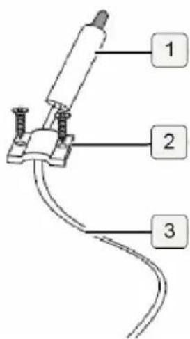
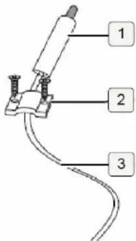
The foil temperature sensor is installed directly on the infrared heating plate and fixed with a cable strain relief (see Fig. 5: Installing the foil temperature sensor on page 13)
Install the sensor head ① of the foil temperature sensor directly between the insulation and heating foil ④.
- Secure the foil temperature sensor with the strain relief ② outside the foil area.
- Lay the 2-pin cable ③ in the cabin wall and secure with cable ties.
- A foil temperature sensor must be activated to use it (6.4. Foil sensor on page 22).
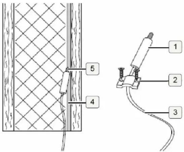
Fig. 5: Installing the foil temperature sensor
If the foil temperature sensor is not fitted directly on the infrared plate, it will produce incorrect measured values. Install the foil temperature sensor directly on the foil.
5. Electrical connection
Observe the following points when connecting the power to the infrared controller:
- Work on the infrared controller may only be performed when the power has been disconnected.
All components on the Infrabox power supply unit are connected as shown in the figures below:
5.1. Connection area for sensor/control unit
Fig. 6: Connection area for sensor/control unit
1 Seat sensor (optional)
rd = red = rot
② Foil temperature sensor (FF)
wt = white = weiß
Safety temperature limiter (STB)
bk = black = schwarz
③ Infrabox control unit
5.2. Connection diagram for 230 V
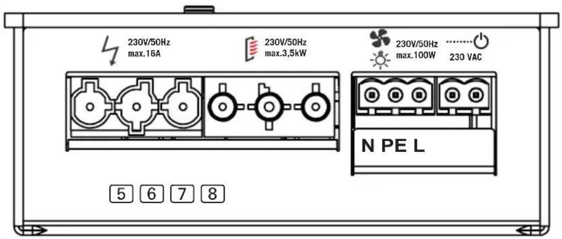
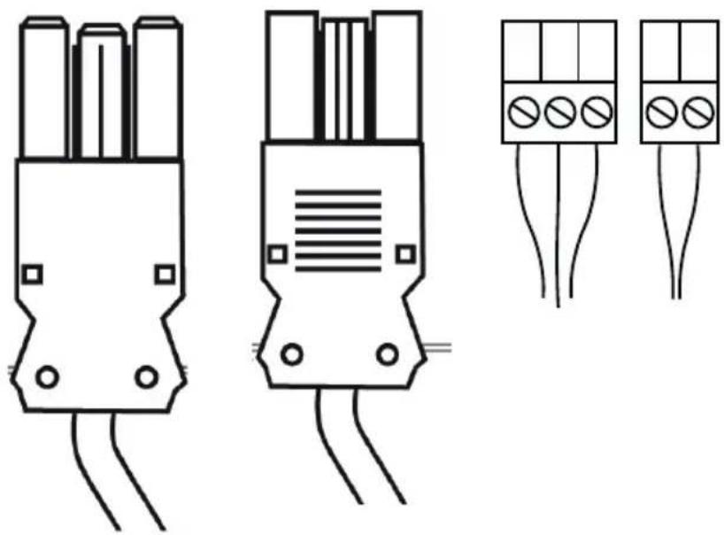
Fig. 7: Connection area for 230 V
5 Mains connection cable 230 V / 50 Hz max. 16 A
6 Infrared heater max. 3.5 kW
7 Light connection or fan connection
8 HV input (230 V / 50 Hz)
N = neutral line (bl = blue = blau)
PE = earth conductor
(ye / gn = yellow / green = gelb / grün)
L = outer conductor (br = brown = braun)
WARNING!
Personal injury
- The clamping connections may only be installed by a qualified electrician or similarly qualified person.
5.3. Connecting the light / fan
Clamp the light or fan to the 3-pin light/fan plug according to Fig. 7: Connection area for 230 V on page 15.

5.4. Connecting the seat sensor (optional)
Clamp the seat sensor line to the 3-pin seat sensor plug according to Fig. 6: Connection area for sensor/control unit on page 14. Observe the instructions for this in the operating instruction manual.
5.5. Connecting the foil sensor (optional)
Clamp the foil sensor line on the 2-pin foil sensor plug to FF according to Fig. 6: Connection area for sensor/control unit on page 14.
5.6. Connecting the HV input (remote start/enable input)
The input becomes active by applying alternating current (230 V / 50 Hz) – depending on the remote start or enable input setting. The input is connected using 2-pole HV plug according to Fig. 7: Connection area for 230 V on page 15.
The EN 60335-2-53 states that the controller (in the remote start setting) must be set to “Standby for remote operation” mode before each remote start procedure.
Refer to chapter 6.9. HV input (remote start/enable input) on page 29 to follow the exact step-by-step procedure.
5.7. Connecting the safety temperature limiter (optional)
When using infrared heaters and infrared plates without intrinsic safety, a safety temperature limiter is required and must be connected!
The STB line is connected as shown in Fig. 6: Connection area for sensor/control unit on page 14 to the STB connection.
5.8. Connecting the infrared heater / infrared plate
Connect the infrared heater/infrared plate to the connection provided according to Fig. 7: Connection area for 230 V on page 15. Observe the instructions for this in the operating instruction manual.

230V/50Hz max.3,5kW
EN
6. Starting up
By default, all function selection switches are set to OFF.
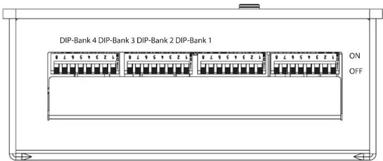
Fig. 8: Function selection switch – Standard setting
Each DIP Bank provides setting options for the product features of Infrabox, which are listed below and described in detail.
The settings made in each function setting are shown in the DIP-Bank as well as the function selection switch.
Note that the controller needs to be disconnected from the mains for 10 seconds after making changes so that the settings are saved.
For standard deliveries, the features are as follows:
Operating mode: Normal
Operating type: Switch
Operating time: 6 hours
Foil sensor: Off
Leading/trailing edge phase control: Not activated
HV input: The remote start takes place by applying alternating current (230 V / 50 Hz) at remote start input.
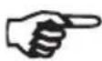
6.1. Operating mode
DIP-Bank 1
Function selection switch 1 and 2
In the operating mode the following settings are possible:
| Function selec- tion switch | 1 | 2 |
| Normal OFF OFF | ||
| Timer I/0 ON OFF | ||
| Timer I/0/I OFF ON | ||
| Seat (optional) ON ON | ||
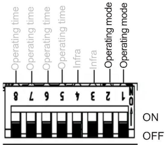
Fig. 9: Operating mode
Normal: Dimmable light / fan. Switchable or dimmable infrared heater/infrared plate.
Activating the dimming function of the infrared heater/infrared plate is done via the infra-controller, see 6.2. Operating type (infrared heater/infrared plate) on page 20.
Timer I/0 (On/Off): In the operating mode, On/Off switches the controls off after the set On-time has elapsed and is not activated again.
Dimmable light / fan. Switchable infrared heater / infrared plate.
For additional settings, see 6.6. On-time (I/0 and I/0/I) on page 24 and Fig. 18: Timer I/0 operating mode on page 28.
Timer I/0/1 (On/Off/On): In the operating mode, On/Off/On switches the infrared controller off after the elapsed On-time and, after the set Off-time, is activated again for the duration of the On-time.
Dimmable light / fan. Switchable infrared heater / infrared plate.
For additional settings, see 6.6. On-time (I/0 and I/0/I) on page 24, 6.7. Out-time (I/0/I) on page 26 and Fig. 18: Timer I/0 operating mode on page 28, Fig. 19: Timer I/0/I operating mode on page 28.
Seat (Function is only available in combination with the optional seat sensor): Dimmable light / fan. Switchable or dimmable infrared heater/infrared plate.
Activating the dimming function of the infrared heater/infrared plate is done via the infra-controller, see 6.2. Operating type (infrared heater/infrared plate) on page 20.
For additional settings, see 6.5. Seat time (optional for seat sensor) on page 23.
6.2. Operating type (infrared heater/infrared plate)
DIP-Bank 1
Function selection switch 3 and 4
The following settings are possible for the infra-controller:
| Function selection switch | 3 | 4 |
| Switch OFF OFF | ||
| Leading edge phase control | ON OFF | |
Half-wave control OFF ON
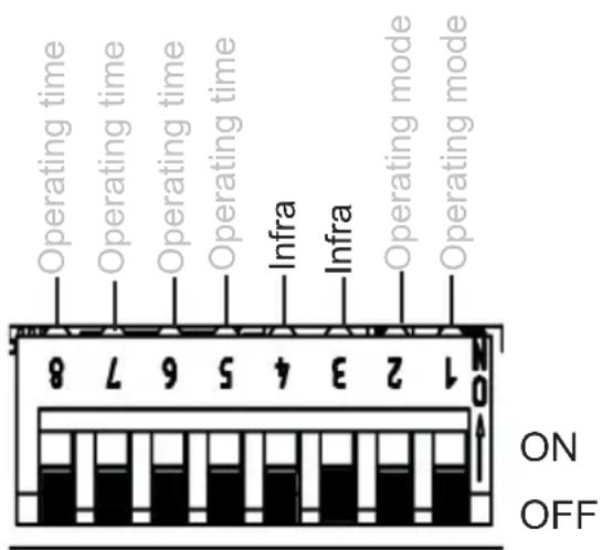
Fig. 10: Infrared operating type
To enable optimum functionality, we recommend the phase control function for infrared heaters with visible light. The half-wave control function is suitable for infrared plates and infrared heaters without visible light.
ATTENTION!
The specified output limits may not be exceeded!
Switching: Switching the infrared heater or infrared plate with a heating capacity of max. 3.5 kW. No dimming function.
Leading edge phase control: Controlling (dimming) the infrared heater/infrared plate is possible in 5 levels up to 350 W.
Half-wave control: Controlling (dimming) the infrared heater/infrared plate is possible in 5 levels up to 1.3 kW.
6.3. Operating time
DIP-Bank 1
Function selection switch 5 - 8
The maximum operating time is set to 6 hours as standard. The infrared controller shuts down automatically after the maximum heating period for safety reasons.
The function selection switch in the low-voltage connection area can be adjusted to the maximum operating time. The required positions of the function selection switch can be found in the following table.
Fig. 11: Operating time

The EN 60335-2-53 specifies a maximum heating period limit of 6 hours for private saunas. For saunas in hotels, apartment blocks and similar locations, a maximum heating period limit of 12 hours is permissible. Extending the heating period limit to 18 hours or 24 hours is only permitted in public saunas.
| Time | Function selection switch | |||
| 8 7 6 5 | ||||
| 5 min ON ON ON ON | ||||
| 10 min ON ON ON OFF | ||||
| 15 min ON ON OFF ON | ||||
| 30 min ON OFF ON ON | ||||
| 45 min ON OFF ON OFF | ||||
| 60 min ON OFF OFF ON | ||||
| 2 hours ON OFF OFF OFF | ||||
| 3 hours OFF ON ON ON | ||||
| 4 hours OFF ON ON OFF | ||||
| 5 hours OFF ON OFF ON | ||||
| 6 hours OFF OFF OFF OFF | ||||
| 12 hours OFF OFF OFF ON | ||||
| 18 hours OFF OFF ON OFF | ||||
| 24 hours OFF OFF ON ON | ||||
6.4. Foil sensor
DIP-Bank 4
Function selection switch 3
If an infrared plate is connected to the infrared output, the WC4-IRF-F foil sensor must be used. The foil sensor must be activated according to the adjacent figure by putting switch 3 to ON.
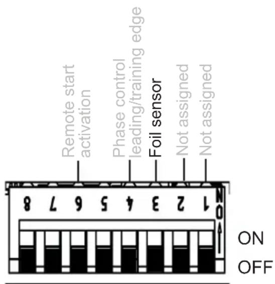
Fig. 12: Foil sensor
6.5. Seat time (optional for seat sensor)
DIP-Bank 2
Function selection switch 1 and 2
By selecting the seat time, the time for the optional seat sensor available can be set. After the set operating time has elapsed, the infrared heater/infrared plate switches off automatically.
The operating time can be adjusted using the function selection switch. For the required position of the function selection switch, see the following table.
| Function selection switch | 1 | 2 |
| 5 min OFF OFF | ||
| 10 min ON OFF | ||
| 15 min OFF ON | ||
| 20 min ON ON | ||
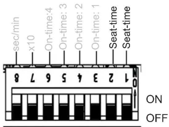
Fig. 13: Seat-time
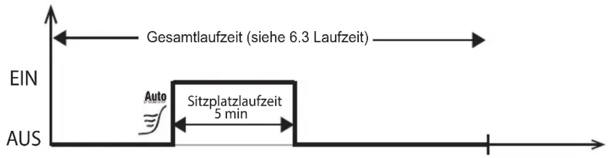
Note: Seat operating mode (see 6.1. Operating mode on page 19) must be activated to be able to use the function.
Example: Seat-time 5 min
6.6. On-time (I/0 and I/0/I)
DIP-Bank 2
Function selection switch 3 - 6
Note: To activate the On-time, additional settings are required, see 6.1. Operating mode on page 19 and Fig. 18: Timer I/0 operating mode on page 28 and Fig. 19: Timer I/0/I operating mode on page 28
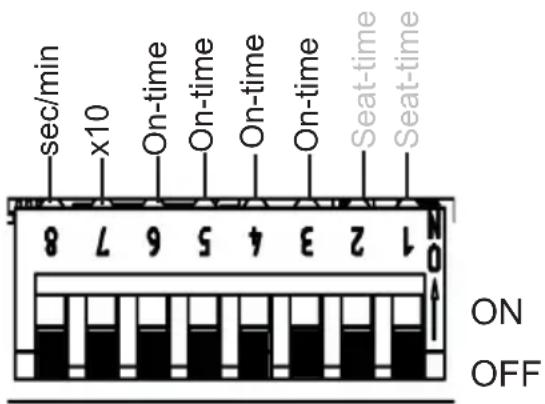
Fig. 14: On-time
Function of the On-time: output begins to run or to clock after switching on the controller according to the set times.
On-time: Setting the timer (timer function). Switching position of the required value to ON according to the following table.
x10 - multiplicator (7): The timer set above the value is multiplied by 10.
OFF = deactivated, ON = activated
sec/min – unit (8): Switching from seconds to minutes.
OFF = seconds, ON = minutes
Example: Setting time 3 minutes
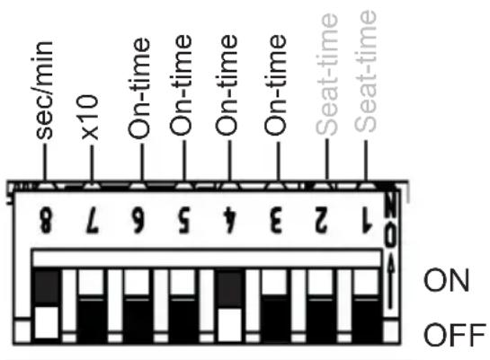
Fig. 15: Example On-time
Function selection switch 1 - 5
Note: To activate the Off-time, additional settings are required, see 6.1. Operating mode on page 19 and Fig. 18: Timer I/0 operating mode on page 28 and Fig. 19: Timer I/0/I operating mode on page 28
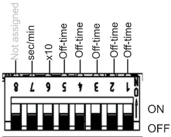
Fig. 16: Off-time
Function of the Off-time: the output switches off after the set time (see 6.6. On-time (I/0 and I/0/I) on page 24) and remains inactive for the Off-time. Depending on the setting of the operating mode (see 6.1. Operating mode on page 19), the infrared controller remains inactive or activates again after a set time.
Off-time: Setting the timer (timer function). Switching position of the required value to ON according to the following table.
x10 - multiplicator (6): The timer set above the value is multiplied by 10.
OFF = deactivated, ON = activated
sec/min – unit (7): Switching from seconds to minutes.
OFF = seconds, ON = minutes
Example: Setting time 210 minutes
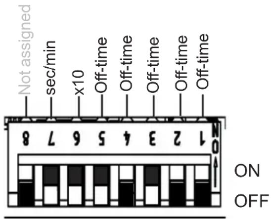
Fig. 17: Example for Off-time
Timer operating mode I/O (On/Off): in the On/Off operating mode, the controller switches off after the set On-time has elapsed and is not activated again.
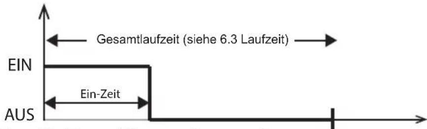
Fig. 18: Timer I/O operating mode
Timer I/0/1 (On/Off/On) operating mode: In the On/Off/On operating mode, the infrared controller switches off after the elapsed On-time and, after the set Off-time, is activated again for the duration of the On-time.
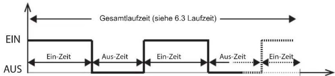
Fig. 19: Timer I/0/I operating mode
6.8. Leading/trailing edge phase control
DIP-Bank 4
Function selection switch 4
Setting options:
Leading edge phase control: OFF (standard)
Trailing edge phase control: ON
For activating the leading/trailing edge phase control, additional settings are required, see 6.1. Operating mode on page 19.
Function is available in the normal and seat modes (optional).
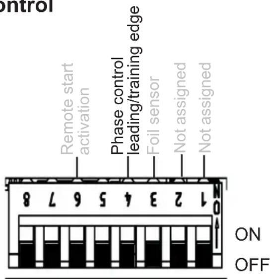
Fig. 20: Leading/trailing edge phase control
When the leading edge phase control mode is (see 6.2. Operating type (infrared heater/infrared plate) on page 20) selected, there is the option of selecting between leading/trailing edge phase control.
6.9. HV input (remote start/enable input)
DIP-Bank 4
Function selection switch 6
Remote start (OFF position)
The unit can be controlled remotely.
The controller starts after applying voltage (230 VAC) at the HV input with the previously set values. To do this the controller must be held down for approx. 3 seconds to put the mode button in the “Standby for remote operation”.
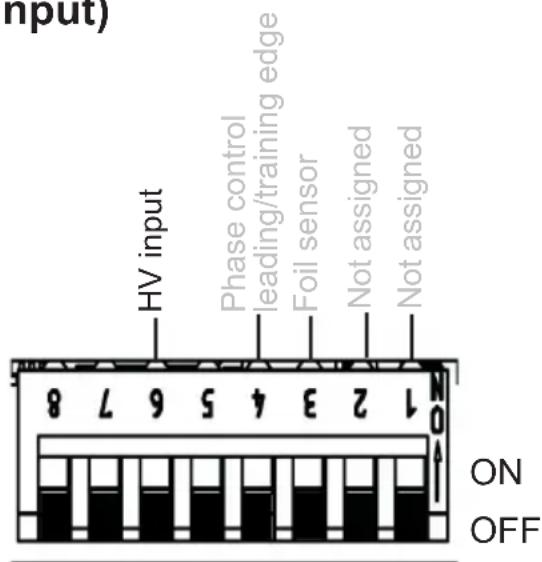
Fig. 21: HV input
Enable input (ON position)
The controller can only be switched on if 230 VAC is applied at the HV input. This function can be used with a vending machine for example.
See also 5.6. Connecting the HV input (remote start/enable input) on page 16.
7. Performing tests
The following tests must be performed by a certified electrical fitter.
WARNING!
The following tests must be performed with the power supply switched on. There is a danger of electric shock.
- NEVER touch live parts.
- Check the contact of the earth conductors on the earth conductor terminal.
- When using a foil sensor (see Fig. 6: Connection area for sensor/control unit on page 14)
a. Unplug the sensor. Error code 3 (see 11.1. Error messages on page 37) is displayed.
b. When the correct code is displayed, plug the sensor in again.
- When using a safety temperature limiter (see Fig. 6: Connection area for sensor/control unit on page 14)
a. Unplug the safety temperature limiter. Error code 2 (see 11.1. Error messages on page 37) is displayed.
b. When the correct code is displayed, plug the limiter in again.
- When using the light/fan (see Fig. 7: Connection area for 230 V on page 15)
a. Check for functionality.
- When using the infrared plate/infrared heater (see Fig. 7: Connection area for 230 V on page 15)
a. Check for functionality.
8. Safety information for the user
- The infrared controller must not be used by children under 8 years old.
- The infrared controller may be used by children age 8 years or older, by persons with limited psychological, sensory or mental capabilities or by persons with lack of experience/knowledge only when:
– They are supervised.
– They have been shown how to use the device safely and are aware of the hazards that could occur.
- Children must not play with the device.
- Children under 14 years old may only clean the device if they are supervised.
- For health reasons, do not use the infrared cabin if you are under the influence of alcohol, medication or drugs.
- Before the infrared controller is switched on, make sure that no flammable objects have been hung over the infrared heater or on the infrared plate.
- For your own safety, consult your supplier in the event of problems that are not described in sufficient detail in the operating instructions.
9. Operation
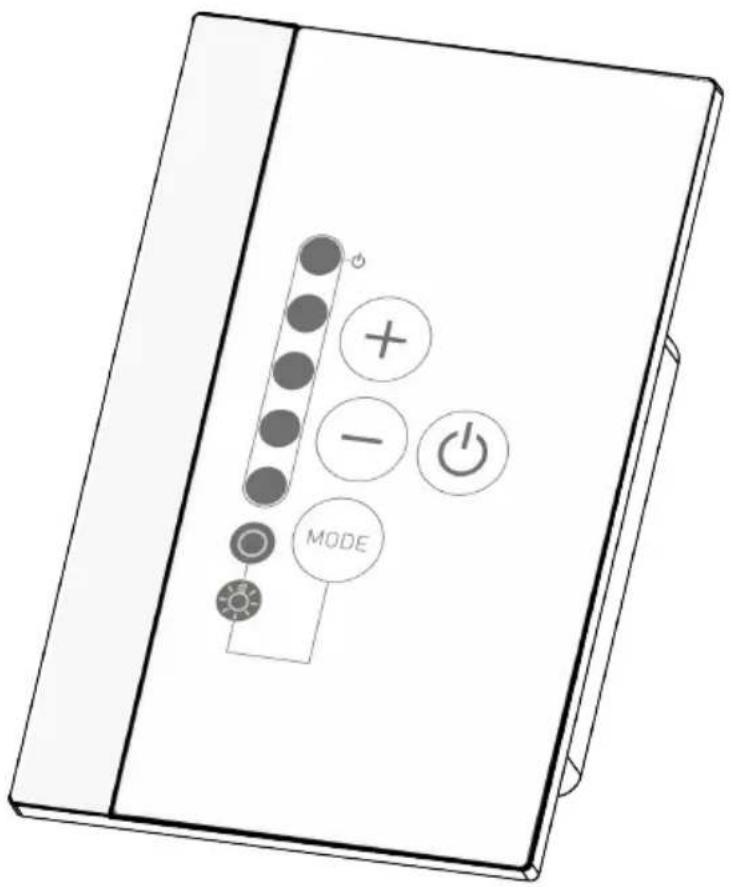
9.1. Description of control elements
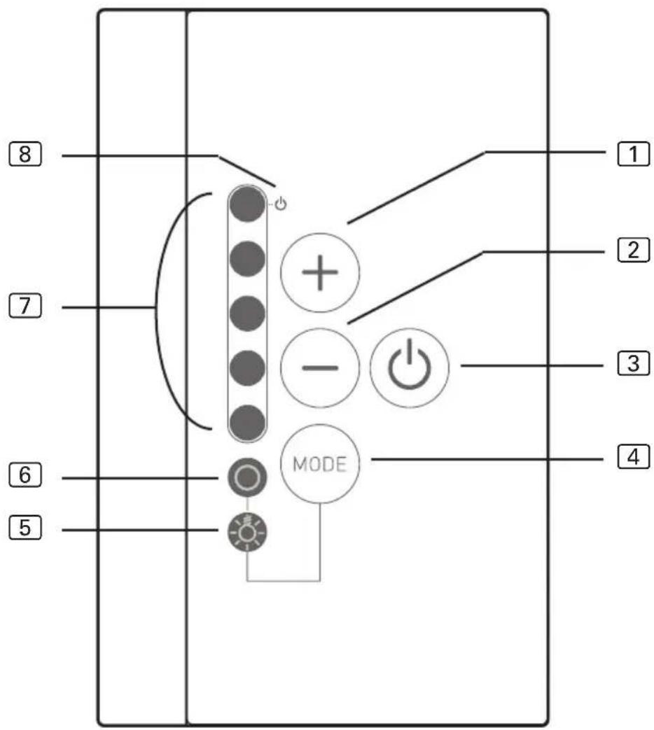
① Increase intensity/ Normal operating mode: On
② Decrease intensity/ Normal operating mode: Off
③ ON/OFF button
④ Mode button: Selects between light/fan and infrared heater controller
⑤ Controls the light/fan
6 Controls the infrared heater/infrared plate
7 Intensity displays/ On/Off display
8 Standby for remote operation display
WARNING!
Risk of fire
- Before the infrared controller is switched on, make sure that no flammable objects have been hung over the infrared heater or on the infrared plate.
9.2. Switching the infrared controller
- Press the ON/OFF switch ③, to switch on the infrared controller.
▶ The light/fan and the infrared heater/infrared plate display lights up.
-
Using Mode button 4, you can select between the intensity control for infrared heater/infrared plate 6 and light/fan 5.
-
Select the intensity of the function with the intensity selector 1 and 2.
▶ The infrared heater/the infrared plate begins to heat up.
9.3. Activating the dimming function for the light/fan
You can control (dim) the light or fan in 5 levels. At 0 the light/fan is switched off, at 5 it is a full capacity.
- Press the Mode button 4.
▶ The light symbol for light/fan 5 lights up.
- Use the intensity selector 1 and 2 to set the preferred intensity of light.
▶ The light operates at the level of intensity selected.
9.4. Dimming function for infrared heater/infrared plate
Controlling (dimming) the infrared heater/infrared plate is possible in 5 levels. At 0 the infrared heater/infrared plate is switched off, at 5 it is a full capacity.
Function only possible in operating modes: leading edge phase control and half-wave control
To activate the function, additional settings are required, see chapter 6.2. Operating type (infrared heater/infrared plate) on page 20
Function only possible in operating mode: normal and seat
To activate the function, additional settings are required, see chapter 6.1. Operating mode on page 19
- Press the Mode button.
▶ The light symbol for infrared heater/infrared plate ⑥ lights up.
- Use the intensity selector 1 and 2 to set the preferred intensity of heat.
▶ The light operates at the level of intensity selected.
9.5. Standby for remote operation
To activate this function, observe the following procedure:
WARNING!
Risk of fire
- Before the infrared controller is switched on, make sure that no flammable objects have been hung over the infrared heater or on the infrared plate.
- Check the cabin to make sure that no flammable objects are hanging over the infrared heater/infrared plate.
- Close the doors of the cabin.
- Press Mode button ④ for approx. 3 seconds (when switched off).
▶ The display for Standby for remote operation ⑧ flashes. - The cabin is ready to operate once the 230 V is connected up.
To deactivate the “Standby for remote operation” function, observe the following procedure:
- Press the ON/OFF button 3.
▶ The controller starts.
- Repress the ON/OFF button 3.
▶ The controller switches off.
▶ The function for “Standby for remote operation” is deactivated.
The EN 60335-2-35 states that infrared controllers with remote start function must be activated again to “Standby for remote operation” mode before each remote start procedure.
9.6. Seat sensor (optional)
When using a seat sensor (available as an option), the infrared output for the set seat time switches on automatically if you have set it previously.
The infrared control unit must be switched on to do so (see 9.2. Switching the infrared controller on page 33)
10. Cleaning and maintenance
10.1. Cleaning
ATTENTION!
Damage to the unit
The Infrabox is protected against jets of water, however direct contact with water could still damage the unit.
- Never immerse the device in water.
- Never pour water over the device.
-
Never clean the device with a cloth which is too wet.
-
Immerse a cleaning cloth in a mild, soapy solution.
- Wring the cleaning cloth out well.
- Wipe the housing of the infrared controller carefully.
10.2. Maintenance
The infrared controller is maintenance-free.
11. Disposal
- Please dispose of packaging materials in accordance with the applicable disposal regulations.
- Used devices contain reusable materials and hazardous substances. Therefore, do not dispose of your used device with household waste, but do so in accordance with the locally applicable regulations.
12. Troubleshooting
12.1. Error messages
The Infrabox is equipped with diagnostic software which monitors system statuses when it switches on and during operation. As soon as the diagnostic software detects an error, the controller switches off the infrared output, the light/fan output remains active.
Errors are indicated by the LEDs flashing.
Switch the infrared controller off using the ON/OFF switch ③ (see 9.1. Description of control elements on page 32), unplug the cable from the mains and rectify the error before switching the infrared controller on again.
The following table describes the possible errors and their causes. If necessary, tell the number of the flashing LEDs to your customer service specialist.
| Number of LED | Error Cause / rectification | |
| 1 General information Please contact customer support. | ||
| 2 Safety temperature limiter breakage | Check the safety temperature limiter or put a bridge in safety temperature limiter terminal. | |
| 3 Foil temperature sensor is broken or short circuited | Defective temperature sensor or poor contact or short circuit. | |
| 4 Foil sensor excess temperature | The maximum foil temperature of 100 °C was exceeded. Sensor must be activated via DIP. | |
| 5 Communication error between control unit and power supply unit | Poor contact or defect connection cable. Please contact customer support. | |
13. Technical data
Operating unit
| Connection: 4-pin with power supply and communication lines | ||
| Mains voltage: 5 V DC | ||
| Output: | <0.5 | W |
| Storage temperature: -25 °C to 70 °C | ||
| Ambient temperature: -10 °C to +110 °C | ||
| Relative humidity: max. 99% rel. humidity, | non-condensing! | |
| Dimensions: L x W x D 63 x 104 x 38 mm | ||
| Installation cut-out: L x B 48 x 60 mm | ||
Power unit
| Nominal voltage | 230 | VAC | |
| Dimensions | 195 x 119 x 48 mm | ||
| Connection cable | 3 x 1.5 mm2 for light, | Electronics and heating elements | |
| Contact rating / heater | |||
| Leading edge phase control | 350 W | ||
| Half-wave control | 1.3 | kW | |
| Switching | 3.5 | kW | |
| Ambient conditions | 10 °C to +40 °C | ||
| Light/fan power | 100 | W | |
Thermal safety
Adjustable automatic heating period (6 h, 12 h, 18 h, 24 h)*
Infrarotsteuerung
infrabox
Infrabox Set 1-035-704 / IRB-S
Infrabox white Set 1-039-846 / IRB-S-W
Inhaltsverzeichnis
Abb. 5: Montage des Folientemperatur-Fühlers

N = Neutralleiter (bl = blue = blau)
PE = Schutzleiter (ye/gn = yellow/green = gelb / grün)
L = Außenleiter (br = brown = braun)

WARNUNG!
Personenschaden
Kit Infrabox 1-035-704 / IRB-S
Kit Infrabox white 1-039-846 / IRB-S-W
Table des matières
1. Concernant ces instructions 4
OFF = secondes, ON = minutes
Infrabox Set
1-035-704/IRB-S
Infrabox white Set 1-039-846/IRB-S-W
SV
Lämpliga IR-plattor: IR-WP-175, IR-WP-100, IR-WP-390, IR-WP-510, IR-WPHL-510, IR-WPHL-100, IR-WPHL-390, IR-WPHL-175
OBS!
OFF = sekunder, ON = minuter
OFF = sekunder, ON = minuter
Fasskärning bakkant: ON
Infrabox-sarja 1-035-704 / IRB-S
Infrabox white -sarja 1-039-846 / IRB-S-W
FI
Sisällysluettelo
Комплект Infrabox 1-035-704 / IRB-S
Komplekt Infrabox 1-035-704 / IRB-S
Komplekt Infrabox white 1-039-846 / IRB-S-W
ET
Sisukord
Joon 1: Toiteploki paigaldamine
Joon 4: Juhtpaneeli paigaldamine

Joon 5: Kile-temperatuurianduri paigaldamine

| Aeg | Funktsioonivalikulüliti | |||
| 8 7 6 5 | ||||
| 5 min SEES SEES SEES SEES | ||||
| 10 min SEES SEES SEES VÄLJAS | ||||
| 15 min SEES SEES VÄLJAS SEES | ||||
| 30 min SEES VÄLJAS SEES SEES | ||||
| 45 min SEES VÄLJAS SEES VÄLJAS | ||||
| 60 min SEES VÄLJAS VÄLJAS SEES | ||||
| 2 h SEES VÄLJAS VÄLJAS VÄLJAS | ||||
| 3 h VÄLJAS SEES SEES SEES | ||||
| 4 h VÄLJAS SEES SEES VÄLJAS | ||||
| 5 h VÄLJAS SEES VÄLJAS SEES | ||||
| 6 h VÄLJAS VÄLJAS VÄLJAS VÄLJAS | ||||
| 12 h VÄLJAS VÄLJAS VÄLJAS SEES | ||||
| 18 h VÄLJAS VÄLJAS SEES VÄLJAS | ||||
| 24 h VÄLJAS VÄLJAS SEES SEES | ||||
6.4. Kileandur
DIP-lülitiplokk 4
| Aeg | Funktsioonivalikulūliti | |||
| 6 5 4 3 | ||||
| 1 VÄLJAS VÄLJAS VÄLJAS VÄLJAS | ||||
| 2 VÄLJAS VÄLJAS VÄLJAS SEES | ||||
| 3 VÄLJAS VÄLJAS SEES VÄLJAS | ||||
| 4 VÄLJAS VÄLJAS SEES SEES | ||||
| 5 VÄLJAS SEES VÄLJAS VÄLJAS | ||||
| 6 VÄLJAS SEES VÄLJAS SEES | ||||
| 7 VÄLJAS SEES SEES VÄLJAS | ||||
| 8 VÄLJAS SEES SEES SEES | ||||
| 9 SEES VÄLJAS VÄLJAS VÄLJAS | ||||
| 10 SEES VÄLJAS VÄLJAS SEES | ||||
| 11 SEES VÄLJAS SEES VÄLJAS | ||||
| 12 SEES VÄLJAS SEES SEES | ||||
| 13 SEES SEES VÄLJAS VÄLJAS | ||||
| 14 SEES SEES VÄLJAS SEES | ||||
| 15 SEES SEES SEES VÄLJAS | ||||
| 16 SEES SEES SEES SEES | ||||
| Aeg | Funktsioonivalikulüliti | ||||
| 5 4 3 2 1 | |||||
| 1 VÄLJAS VÄLJAS | VÄLJAS VÄLJAS VÄLJAS | ||||
| 2 VÄLJAS VÄLJAS | VÄLJAS VÄLJAS SEES | ||||
| 3 VÄLJAS VÄLJAS | VÄLJAS SEES VÄLJAS | ||||
| 4 VÄLJAS VÄLJAS | VÄLJAS SEES SEES | ||||
| 5 VÄLJAS VÄLJAS | SEES VÄLJAS VÄLJAS | ||||
| 6 VÄLJAS VÄLJAS | SEES VÄLJAS SEES | ||||
| 7 VÄLJAS VÄLJAS | SEES SEES VÄLJAS | ||||
| 8 VÄLJAS VÄLJAS | SEES SEES SEES | ||||
| 9 VÄLJAS SEES VÄLJAS VÄLJAS | |||||
| 10 VÄLJAS SEES VÄLJAS VÄLJAS SEES | |||||
| 11 VÄLJAS SEES VÄLJAS SEES VÄLJAS | |||||
| 12 VÄLJAS SEES VÄLJAS SEES SEES | |||||
| 13 VÄLJAS SEES SEES VÄLJAS VÄLJAS | |||||
| 14 VÄLJAS SEES SEES VÄLJAS SEES | |||||
| 15 VÄLJAS SEES SEES SEES VÄLJAS | |||||
| 16 VÄLJAS SEES SEES SEES SEES | |||||
| 17 SEES VÄLJAS VÄLJAS VÄLJAS VÄLJAS | |||||
| 18 SEES VÄLJAS VÄLJAS VÄLJAS SEES | |||||
| 19 SEES VÄLJAS VÄLJAS SEES VÄLJAS | |||||
| 20 SEES VÄLJAS VÄLJAS SEES SEES | |||||
| 21 SEES VÄLJAS SEES VÄLJAS VÄLJAS | |||||
| 22 SEES VÄLJAS SEES VÄLJAS SEES | |||||
| 23 SEES VÄLJAS SEES SEES VÄLJAS | |||||
| 24 SEES VÄLJAS SEES SEES SEES | |||||
| 25 SEES SEES VÄLJAS VÄLJAS VÄLJAS | |||||
sentiotec GmbH | Division of Harvia Group I
Wartenburger Straße 31,
A-4840 Vöcklabruck
T +43 (0) 7672/22 900-50 | F -80 |
info@sentiotec.com | www.sentiotec.com
GLOBAL
HARVIA
- INFRARED CONTROL UNIT
- INFRABOX
- INSTRUCTIONS FOR INSTALLATION AND USE ENGLISH
- TABLE OF CONTENTS
- ABOUT THIS INSTRUCTION MANUAL 4
- IMPORTANT INFORMATION FOR YOUR SAFETY 5
- PRODUCT DESCRIPTION 8
- INSTALLATION 10
- ELECTRICAL CONNECTION 14
- STARTING UP 18
- PERFORMING TESTS 30
- SAFETY INFORMATION FOR THE USER 31
- OPERATION 32
- CLEANING AND MAINTENANCE
- DISPOSAL
- TROUBLESHOOTING 37
- TECHNICAL DATA
- ABOUT THIS INSTRUCTION MANUAL
- SYMBOLS USED FOR WARNING NOTICES
- DANGER
- WARNING
- CAUTION
- ATTENTION
- OTHER SYMBOLS
- IMPORTANT INFORMATION FOR YOUR SAFETY
- INTENDED USE
- OVERVIEW OF THE OPERATING MODES
- SAFETY INFORMATION FOR THE INSTALLER
- PRODUCT DESCRIPTION
- SCOPE OF DELIVERY
- OPTIONAL ACCESSORIES
- PRODUCT FUNCTIONS
- INSTALLATION
- INSTALLING THE POWER SUPPLY UNIT
- DAMAGE TO THE UNIT
- INSTALLING THE CONTROL UNIT
- INSTALLING THE FOIL TEMPERATURE SENSOR
- ELECTRICAL CONNECTION
- CONNECTION AREA FOR SENSOR/CONTROL UNIT
- CONNECTION DIAGRAM FOR 230 V
- PERSONAL INJURY
- CONNECTING THE LIGHT / FAN
- CONNECTING THE SEAT SENSOR (OPTIONAL)
- CONNECTING THE FOIL SENSOR (OPTIONAL)
- CONNECTING THE HV INPUT (REMOTE START/ENABLE INPUT)
- CONNECTING THE SAFETY TEMPERATURE LIMITER (OPTIONAL)
- CONNECTING THE INFRARED HEATER / INFRARED PLATE
- STARTING UP
- FOR STANDARD DELIVERIES, THE FEATURES ARE AS FOLLOWS
- OPERATING MODE
- DIP-BANK 1
- FUNCTION SELECTION SWITCH 1 AND 2
- OPERATING TYPE (INFRARED HEATER/INFRARED PLATE)
- FUNCTION SELECTION SWITCH 3 AND 4
- OPERATING TIME
- FUNCTION SELECTION SWITCH 5 - 8
- FOIL SENSOR
- DIP-BANK 4
- FUNCTION SELECTION SWITCH 3
- SEAT TIME (OPTIONAL FOR SEAT SENSOR)
- DIP-BANK 2
- ON-TIME (I/0 AND I/0/I)
- FUNCTION SELECTION SWITCH 3 - 6
- FUNCTION SELECTION SWITCH 1 - 5
- LEADING/TRAILING EDGE PHASE CONTROL
- FUNCTION SELECTION SWITCH 4
- HV INPUT (REMOTE START/ENABLE INPUT)
- FUNCTION SELECTION SWITCH 6
- REMOTE START (OFF POSITION)
- ENABLE INPUT (ON POSITION)
- PERFORMING TESTS
- SAFETY INFORMATION FOR THE USER
- OPERATION
- DESCRIPTION OF CONTROL ELEMENTS
- RISK OF FIRE
- SWITCHING THE INFRARED CONTROLLER
- ACTIVATING THE DIMMING FUNCTION FOR THE LIGHT/FAN
- DIMMING FUNCTION FOR INFRARED HEATER/INFRARED PLATE
- STANDBY FOR REMOTE OPERATION
- SEAT SENSOR (OPTIONAL)
- CLEANING
- MAINTENANCE
- TROUBLESHOOTING
- ERROR MESSAGES
- THERMAL SAFETY
- INFRAROTSTEUERUNG
- INHALTSVERZEICHNIS
- WARNUNG
- PERSONENSCHADEN
- TABLE DES MATIÈRES
- CONCERNANT CES INSTRUCTIONS 4
- OBS
- SISÄLLYSLUETTELO
- SISUKORD
- KILEANDUR
- DIP-LÜLITIPLOKK 4
Brand : HARVIA
Model : infrabox IRBS
Category : Remote control