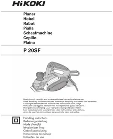
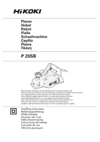
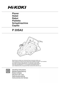
P20SFWAZ - Plane HiKOKI - Free user manual and instructions
Find the device manual for free P20SFWAZ HiKOKI in PDF.


| Product type | Electric planer |
| Brand | HiKOKI |
| Model | P20SFWAZ |
| Voltage | 110 V, 230 V or 240 V depending on region |
| Power | 620 W |
| Cutting width | 82 mm |
| Maximum cutting depth | 2.6 mm |
| Weight (without cord and guide) | 2.5 kg |
| No-load speed | 17000 min⁻¹ |
| Included accessories | Wrench, fixing gauge, guide, blade sharpening device, case (depending on region) |
| Available options | Dust extraction adapter, elbow, dust bag |
| Sound power level | 94 dB(A) |
| Sound pressure level | 83 dB(A) |
| Vibration (planing softwood) | 3.1 m/s² (uncertainty K = 1.5 m/s²) |
| Hearing protection recommended | Yes |
| Safety | Automatic shutdown in case of overload, safety switch, blade brake (quick stop) |
| Maintenance | Regular check of carbon brushes, sharpening or replacing blades, cleaning chips |
| Warranty | Complying with national regulations, excluding misuse |
| After-sales service | HiKOKI authorized center |
| Applications | Planing timber and wood panels |
Frequently Asked Questions - P20SFWAZ HiKOKI
User questions about P20SFWAZ HiKOKI
0 question about this device. Answer the ones you know or ask your own.
Ask a new question about this device
Download the instructions for your Plane in PDF format for free! Find your manual P20SFWAZ - HiKOKI and take your electronic device back in hand. On this page are published all the documents necessary for the use of your device. P20SFWAZ by HiKOKI.
USER MANUAL P20SFWAZ HiKOKI
natural_image
Illustration of a power iron with handle and base plate (no text or symbols)Read through carefully and understand these instructions before use.
natural_image
Simple geometric diagram with a grid pattern inside a square, labeled with numbers 2 and ② (no text or symbols within the diagram itself)



natural_image
Illustration of a manual power tool on a surface, labeled with number 9 and figure 11 (no text or symbols on the tool itself)


13

natural_image
Technical line drawing of a mechanical assembly with bolt holes and a directional arrow (no text or symbols)14

natural_image
Mechanical clamp mechanism diagram showing rotational motion (no text or symbols)15
16

17
18

212019


242322


natural_image
Illustration of a hand inserting a device into a rectangular base, no text or symbols present


| English | Deutsch Français | Italiano | ||
| 1 | Planing Hobeln Rabotage | Piallatura | ||
| 2 | Beveling Abkanten Biseautage | Smussatura | ||
| 3 | Rabberting Falzen Formation de feuillure | Scanalatura | ||
| 4 | Tapering Abschrägen Formation de biais | Rastrematura | ||
| 5 | Knob Knopf Bouton | Manopola | ||
| 6 | Scale Skala Échelle | Scala graduata | ||
| 7 | Mark Markierung Marque | Segno | ||
| 8 | Beginning of cutting operation coupe | Beginn des Hobelns | Début de l'opération de | Inizio dell'operazione di piallatura |
| 9 | End of cutting operation Ende des Hobelns | Fin de l'opération de coupe | Termine dell'operazione di piallatura | |
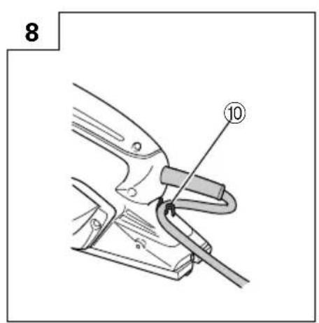
| 10 | Cord holder Kabelhalter Fixation du cordon | Porta-cavo | ||
| 11 | Stand Ständer | Support | Supporto | |
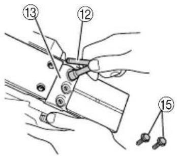
| 12 | Box wrench Steckschlüssel | Clef à béquille | Chiave fissa a collare | |
| 13 | Blade holder | Hobeleisenhalter | Support de lame | Porta-lama |
| 14 | Carbide blade(Double edged blade type) | Hobeleisen mit Hartmetallschneide(Beidseitigen klingentyp) | Lame au carbure(Lames à deux tranchants) | Lama in carburo(tipo lama a doppio filo) |
| 15 | Bolt | Schraube Boulon | Bulloni | |
| 16 | Set plate (B) | Einstellplatte (B) | Plaque de fixation (B) | Piastra di impostazione (B) |
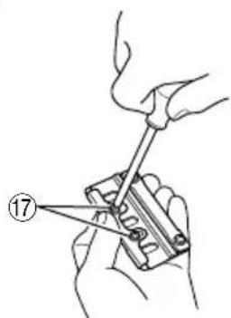
| 17 | Machine screw | Maschinenschraube | Vis machine | Vite |
| 18 | Turned surface | Gebogene Oberfläche | Surface tournée | Superficie curva |
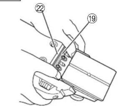
| 19 | Set plate (A) | Einstellplatte (A) | Plaque de fixation (A) | Piastra di impostazione (A) |
| 20 | Set gauge | Einstell-Lehre | Jauge de fixation | Calibro di impostazione |
| 21 | Wall surface b | Wandoberfläche b | Surface du mur b | Superficie parete b |
| 22 | Flat portion of the cutter Block Schneidblocks | acher Teil des lame | Section plate du bloc de | Parte piatta del blocco taglierina |
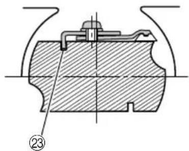
| 23 | Groove | Nut | Encoche | Scanalatura |
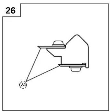
| 24 | Blade(Resharpenable blade type) | Hobeleisen(schärfbarer Klingentyp) | Lame(lame de type réaffutable) | Lama(tipo lama riaffilabile) |
| 25 | Cutter block Schneidblock | Bloc de coupe | Blocco della pialla | |
| 26 | Wall surface a | Wandoberfläche a | Surface du mur a | Superficia parete a |
| 27 | Chip cover | Spanabdeckung | Écran anti-copeaux | Coperchio trucioli |
| 28 | Screw D4 × 16 | Schraube D4 × 16 | Vis D4 × 16 | Vite D4 × 16 |
| 29 | Dust adapter | Staubadapter | Adaptateur anti-poussière | Adattatore polvere |
| 30 | Elbow | Knie | Coude | Gomito |
| 31 | Dust bag | Staubbeutel | Sac à poussière | Sacchetto raccoglipolvere |
| 32 | Wear limit | Verschleißgrenze | Limite d'usure | Limite di usura |
| 33 | No. of carbon brush | Nr. der Kohlebürste | N° du balai en carbone | N. della spazzola di carbone |
| Nederlands | Español | Português | |
| 1 | Schaven Cepillar Aplainamento | ||
| 2 | Afbramen Biselar Chanfragem | ||
| 3 | Groeven Ensamblar Ranhuragem | ||
| 4 | Afschuinen Renatar Estreitamento | ||
| 5 | Knop Botón Manipulo | ||
| 6 | Schaal Escala Escala | ||
| 7 | Merkteken Marca Marca | ||
| 8 | Begin van het schaven | Principio de la operación Inicio da operação de de corte corte | |
| 9 | Einde van het schaven | Fin de la operación de corte | Fim da operação de corte |
| 10 | Snoerhouder Soporte para cable Suporte do cabo | ||
| 11 | Standaard Base Suporte | ||
| 12 | Steeksleutel | Llave anular | Chave de bocas |
| 13 | Schaafijzerhouder | Sujetador de cuchilla | Suporte da lâmina |
| 14 | Koolstofmetaalmes (Mes met dubbele rand) | Cuchilla de carburo (Tipo de cuchilla de doble borde) | Lâmina de carboneto (Tipo de lâmina de fio duplo) |
| 15 | Schroef | Perno | Parafuso |
| 16 | Gemonteerde plaat (B) | Placa de ajuste (B) | Placa do conjunto (B) |
| 17 | Machineschroef | Tornillo de máquina | Parafuso da máquina |
| 18 | Gedraaid oppervlak | Superficie girada | Superfície torneada |
| 19 | Gemonteerde plaat (A) | Placa de ajuste (A) | Placa do conjunto (A) |
| 20 | Gemonteerd meetinstrument | Manómetro de ajuste | Manómetro do conjunto |
| 21 | Muuroppervlak b | Superficie de pared b | Superfície de parede b |
| 22 | Vlakke gedeelte van freeszwart del cortador | Parte plana del bloque cortador | Parte plana do bloco |
| 23 | Groef | Ranura | Ranhura |
| 24 | Mes (Slijpbaar mes) | Cuchilla (Tipo de cuchilla afilable) | Lâmina (Tipo de lâmina possível de afiar) |
| 25 | Snijkop | Bloque del cortador | Bloco cortador |
| 26 | Muuroppervlak a | Superficie de pared a | Superfície de parede a |
| 27 | Spaankast Cubierta de virutas Tampa de aparas | ||
| 28 | Schroef D4 × 16 | Tornillo D4 × 16 | Parafuso D4 × 16 |
| 29 | Stofadapter | Adaptador para el polvo | Adaptador para pó |
| 30 | Elleboogstuk | Codo | Cotovelo |
| 31 | Stofzak Bolsa para el polvo | Saco para pó | |
| 32 | Slijtagegrens Límite de uso | Limite de desgaste | |
| 33 | Nr. van de koolborstel | N° de carbón de contacto | N° de escovas de carvão |
| English | Deutsch | Français | Italiano | |
| SymbolsWARNINGThe following show symbols used for the machine. Be sure that you understand their meaning before use. | SymboleWARNUNGDie folgenden Symbole werden für diese Maschine verwendet.Achten Sie darauf, diese vor der Verwendung zu verstehen. | SymbolesAVERTISSEMENTLes symboles suivants sont utilisés pour l’outil.Bien se familiariser avec leur signification avant d’utiliser l’outil. | SimboliAVVERTENZADi seguito mostriamo i simboli usati per la macchina. Assicurarsi di comprenderne il significato prima dell’uso. | |
 | Read all safety warnings and all instructions.Failure to follow the warnings and instructions may result in electric shock, fire and/or serious injury. | Lesen Sie sämtliche Sicherheitshinweise und Anweisungen durch.Wenn die Warnungen und Anweisungen nicht befolgt werden, kann es zu Stromschlag, Brand und/oder ernsthaftenVerletzungen kommen. | Lire tous les avertissements de sécurité et toutes les instructions.Tout manquement à observer ces avertissements et instructions peut engendrer des chocs électriques, des incendies et/ou des blessures graves. | Leggere tutti gli avvertimenti di sicurezza e tutte le istruzioni.La mancata osservanza degli avvertimenti e delle istruzioni potrebbe essere causa di scosse elettriche, incendi e/o gravi lesioni. |
 | Only for EU countriesDo not dispose of electric tools together with household waste material!In observance of European Directive 2002/96/EC on waste electrical and electronic equipment and its implementation in accordance with national law, electric tools that have reached the end of their life must be collected separately and returned to an environmentally compatible recycling facility. | Nur für EU-Länder Werfen Sie Elektrowerkzeuge nicht in den Hausmüll!Gemäss Europäischer Richtlinie 2002/96/EG über Elektro- und Elektronik- Altgeräte und Umsetzung in nationales Recht müssen verbrauchte Elektrowerkzeuge getrennt gesammelt und einer umweltgerechten Wiederververtung zugeführt werden. | Pour les pays européens uniquementNe pas jeter les appareils électriques dans les ordures ménagères!Conformément à la directive européenne 2002/96/CE relative aux déchets d’équipements électriques ou électroniques (DEEE), et à sa transposition dans la législation nationale, les appareils électriques doivent être collectés à part et être soumis à un recyclage respectueux de l’environnement. | Solo per Paesi UE Non gettare le apparecchiature elettriche tra i rifiuti domestici.Secondo la Direttiva Europea 2002/96/CE sui rifiuti di apparecchiature elettriche ed elettroniche e la sua attuazione in conformità alle norme nazionali, le apparecchiature elettriche esauste devono essere raccolte separatamente, al fine di essere reimpiegate in modo eco-compatibile. |
| n_0 | Velocità a vuotono-loa | |||
| /min or min^-1 | Revolutions or reciprocations per minute | Umdrehungen oder Pendelbewegungen pro Minute | Tours ou mouvements alternatifs par minute | Rivoluzioni o reciprocazioni per minuto |
| ~ | Alternating current Wechselstrom Courant alter natif | Corrente alternata | ||
| 回 | Class II tool Werkzeug der Klasse II Outil classe II | Attrezzo di Classe II | ||
| ⚠️ | Caution Achtung Attention | Attenzione | ||
| V | VoltVolts Volt Volts | |||
| A | AmpereAmperes Amp | |||
| Hz | HertzHertz Hertz Hertz | |||
| W | Watts | Watt | Watts | Watt |
| kg | Kilograms | Kilogramm | Kilogrammes | Kilogrammi |
Read all safety warnings and all instructions.
Failure to follow the warnings and instructions may result in electric shock, fire and/or serious injury.
Save all warnings and instructions for future reference.
The term "power tool" in the warnings refers to your mains-operated (corded) power tool or battery-operated (cordless) power tool.
1) Work area safety
a) Keep work area clean and well lit.
Cluttered or dark areas invite accidents.
b) Do not operate power tools in explosive atmospheres, such as in the presence of flammable liquids, gases or dust.
Power tools create sparks which may ignite the dust or fumes.
c) Keep children and bystanders away while operating a power tool.
Distractions can cause you to lose control.
2) Electrical safety
a) Power tool plugs must match the outlet.
Never modify the plug in any way.
Do not use any adapter plugs with earthed (grounded) power tools.
Unmodified plugs and matching outlets will reduce risk of electric shock.
b) Avoid body contact with earthed or grounded surfaces, such as pipes, radiators, ranges and refrigerators.
There is an increased risk of electric shock if your body is earthed or grounded.
c) Do not expose power tools to rain or wet conditions.
Water entering a power tool will increase the risk of electric shock.
d) Do not abuse the cord. Never use the cord for carrying, pulling or unplugging the power tool.
Keep cord away from heat, oil, sharp edges or moving parts.
Damaged or entangled cords increase the risk of electric shock.
e) When operating a power tool outdoors, use an extension cord suitable for outdoor use.
Use of a cord suitable for outdoor use reduces the risk of electric shock.
f) If operating a power tool in a damp location is unavoidable, use a residual current device (RCD) protected supply.
Use of an RCD reduces the risk of electric shock.
3) Personal safety
a) Stay alert, watch what you are doing and use common sense when operating a power tool.
Do not use a power tool while you are tired or under the influence of drugs, alcohol or medication.
A moment of inattention while operating power tools may result in serious personal injury.
b) Use personal protective equipment. Always wear eye protection.
Protective equipment such as dust mask, non-skid safety shoes, hard hat, or hearing protection used for appropriate conditions will reduce personal injuries.
c) Prevent unintentional starting. Ensure the switch is in the off-position before connecting to power source and/or battery pack, picking up or carrying the tool.
Carrying power tools with your finger on the switch or energising power tools that have the switch on invites accidents.
d) Remove any adjusting key or wrench before turning the power tool on.
A wrench or a key left attached to a rotating part of the power tool may result in personal injury.
e) Do not overreach. Keep proper footing and balance at all times.
This enables better control of the power tool in unexpected situations.
f) Dress properly. Do not wear loose clothing or jewellery. Keep your hair, clothing and gloves away from moving parts.
Loose clothes, jewellery or long hair can be caught in moving parts.
g) If devices are provided for the connection of dust extraction and collection facilities, ensure these are connected and properly used.
Use of dust collection can reduce dust related hazards.
4) Power tool use and care
a) Do not force the power tool. Use the correct power tool for your application.
The correct power tool will do the job better and safer at the rate for which it was designed.
b) Do not use the power tool if the switch does not turn it on and off.
Any power tool that cannot be controlled with the switch is dangerous and must be repaired.
c) Disconnect the plug from the power source and/or the battery pack from the power tool before making any adjustments, changing accessories, or storing power tools.
Such preventive safety measures reduce the risk of starting the power tool accidentally.
d) Store idle power tools out of the reach of children and do not allow persons unfamiliar with the power tool or these instructions to operate the power tool. Power tools are dangerous in the hands of untrained users.
e) Maintain power tools. Check for misalignment or binding of moving parts, breakage of parts and any other condition that may affect the power tool's operation.
If damaged, have the power tool repaired before use. Many accidents are caused by poorly maintained power tools.
f) Keep cutting tools sharp and clean.
Properly maintained cutting tools with sharp cutting edges are less likely to bind and are easier to control.
g) Use the power tool, accessories and tool bits etc. in accordance with these instructions, taking into account the working conditions and the work to be performed.
Use of the power tool for operations different from those intended could result in a hazardous situation.
5) Service
a) Have your power tool serviced by a qualified repair person using only identical replacement parts.
This will ensure that the safety of the power tool is maintained.
PLANER SAFETY WARNINGS
- Wait for the cutter to stop before settling the tool down.
An exposed rotating cutter may engage the surface leading to possible loss of control and serious injury. -
Hold the power tool by insulated gripping surface only, because the cutter may contact its own cord.
Cutting a "live" wire may make exposed metal parts of the power tool "live" and could give the operator an electric shock. -
Use clamps or another practical way to secure and support the workpiece to a stable platform. Holding the work by your hand or against the body leaves it unstable and may lead to loss of control.
-
Do not use the Planer with the blades facing upward (as stationary type planer).
SPECIFICATIONS
| Voltage (by areas)* (110 V, 230 V, 240 V) | ~ |
| Power Input 620 W* | |
| Cutting Width 82 mm | |
| Max. Cutting Depth 2.6 mm | |
| Weight (without cord and guide) 2.5 kg | |
| No-Load Speed 17000 min | -1 |
* Be sure to check the nameplate on product as it is subject to change by areas.
STANDARD ACCESSORIES
- Box Wrench (for securing cutter blade) ...... 1
- Set Gauge (for adjusting cutter height) ..... 1
- Guide (with set screw) 1
- Blade Sharpening Ass'y (for Resharpenable Blade Type) 1
- Case (not supplied in all areas) 1
Standard accessories are subject to change without notice.
OPTIONAL ACCESSORIES (sold separately)
- Dust adapter
- Elbow
- Dust bag
Optional accessories are subject to change without notice.
APPLICATIONS
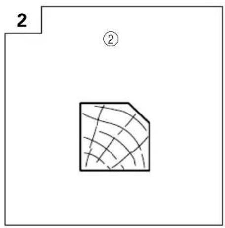
○Planing various wooden planks and panels. (See Fig. 1-4)
PRIOR TO OPERATION
- Power source
Ensure that the power source to be utilized conforms to the power requirements specified on the product nameplate. - Power switch
Ensure that the power switch is in the OFF position. If the plug is connected to a receptacle while the power switch is in the ON position, the power tool will start operating immediately, which could cause a serious accident. -
Extension cord
When the work area is removed from the power source, use an extension cord of sufficient thickness and rated capacity. The extension cord should be kept as short as practicable. -
Prepare a stable wooden workbench suitable for planing operation. As a poorly balanced workbench creates a hazard, ensure it is securely positioned on firm, level ground.
- RCD
The use of a residual current device with a rated residual current of 30mA or less at all times is recommended.
PLANING PROCEDURES
- Adjusting the cutter depth
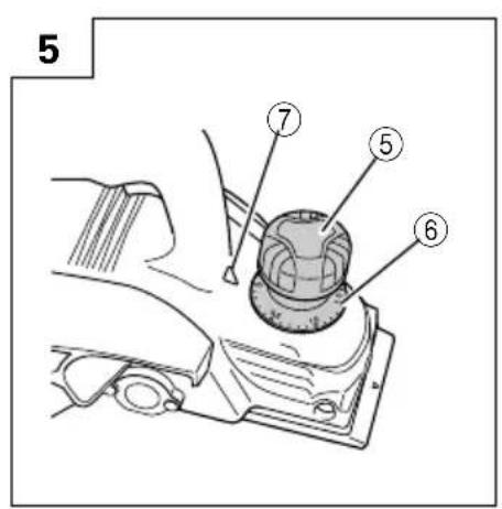
(1) Turn the knob in the direction indicated by the arrow in Fig. 5 (clockwise), until the triangular mark is aligned with the desired cutting depth on the scale. The scale unit is graduated in millimeters.
(2) The cutting depth can be adjusted within a range of 0-2.6 mm.
- Surface cutting
Rough cutting should be accomplished at large cutting depths and at a suitable speed so that shavings are smoothly ejected from the machine. To ensure a smoothly finished surface, finish cutting should be accomplished at small cutting depths and at low feeding speed.
- Beginning and ending the cutting operation
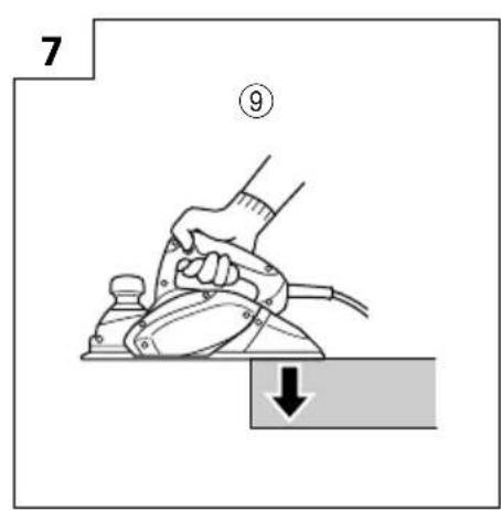
As shown in Fig. 6, place the front base of the planer on the material and support the planer horizontally. Turn ON the power switch, and slowly operate the planer toward the leading edge of the material. Firmly depress the front half of the planer at the first stage of cutting, as shown in Fig. 7, depress the rear half of the planer at the end of the cutting operation. The planer must always be kept flat throughout the entire cutting operation.
- Precaution after finishing the planing operation
When the planer is suspended with one hand after finishing the planing operation, ensure that the cutting blades (base) of the planer do not contact or come too near your body. Failure to do so could result in serious injury.
5. Cord holder
A cord holder is provided on the back of the handle below where the cord is attached. Clip the cord in the holder from right or left depending on which side you want the cord to be. (Fig. 8)
6. Stand
Lift the back of the planer to extend the foot from the base. Having the stand extended when you put the planer down prevents contact between the blade and the material. (Fig. 9)
CARBIDE BLADE ASSEMBLY AND DISASSEMBLY AND ADJUSTMENT OF CUTTER BLADE HEIGHT (FOR DOUBLE EDGED BLADE TYPE)
1. Carbide blade disassembly
(1) As shown in Fig. 10, loosen the blade holder with the attached box wrench.
(2) As shown in Fig. 11, remove the carbide blade by sliding it with the attached box wrench.
CAUTION
Be careful not to injure your hands.
2. Carbide blade assembly
CAUTION
Prior to assembly, thoroughly wipe off all swarf accumulated on the carbide blade.
(1) As shown in Fig. 12, lift set plate (B) and insert the new carbide blade between cutter block and set plate (B).
(2) As shown in Fig. 13, mount the new carbide blade by sliding it on the set plate (B) so that the blade tip projects by 1mm from the end of the cutter block.
(3) As shown in Fig. 14, fix the bolts at the blade holder after blade replacement has been completed.
(4) Turn the cutter block over, and set the other side in the same manner.
3. Adjustment of carbide blade height CAUTION
If the carbide blade's heights are inaccurate after above procedures have been completed, carry out the procedures described below.
(1) As shown in Fig. 15, use the box wrench to loosen the three bolts used to retain the carbide blade, and remove the blade holder.
(2) As shown in Fig. 16, after removing the carbide blade, slide set plate (B) in the direction indicated by the arrow to disassemble set plate (B).
(3) Loosen the 2 screws holding on the carbide blade and set plate (A), set plate (B).
(4) As shown in Fig. 17, 18, press the turned surface of set plate (A) to the wall surface b while adjusting the carbide blade edge to the wall surface a of the set gauge. Then, tighten them with the 2 screws.
(5) As shown in Fig. 19, 20, insert a turned portion of set plate (A) attached to set plate (B) into a groove on the flat portion of the cutter block.
(6) As shown in Fig. 21, place the blade holder on the completed assembly and fasten it with the three bolts. Ensure that the bolts are securely tightened. Follow the same procedures for the opposite side carbide blade.
BLADE ASSEMBLY AND DISASSEMBLY AND ADJUSTMENT OF BLADE HEIGHT (FOR RESHARPENABLE BLADE TYPE)
1. Blade disassembly
(1) As shown in Fig. 15, use the accessory box wrench to loosen the three bolts used to retain the blade, and remove the blade holder.
(2) As shown in Fig. 16, slide the blade in the direction indicated by the arrow to disassemble the blade.
CAUTION
Be careful not to injure your hands.
2. Blade assembly
CAUTION
Prior to assembly, thoroughly wipe off all swarf accumulated on the blade.
(1) Insert a turned portion of set plate (A) attached to the blade into a groove on the flat portion of the cutter block. (Fig. 19, 22)
Set the blade so that both sides of the blade protrude from the width of the cutter block by about 1 mm (Fig. 23)
(2) Place the blade holder on the completed assembly, as shown in Fig. 24, and fasten it with the three bolts. Ensure that the bolts are securely tightened.
(3) Turn the cutter block over, and set the opposite side in the same manner.
3. Adjustment of blade height
(1) Loosen the 2 screws holding on the blade and set plate (A).
(2) Press the turned surface of set plate (A) to the wall surface b while adjusting the blade edge to the wall surface a of the set gauge. Then, tighten them with the 2 screws. (Fig. 17, 25)
SHARPENING THE RESHARPENABLE BLADES
Use of the accessory Blade Sharpening Ass'y is recommended for convenience.
1. Use of Blade Sharpening Ass'y
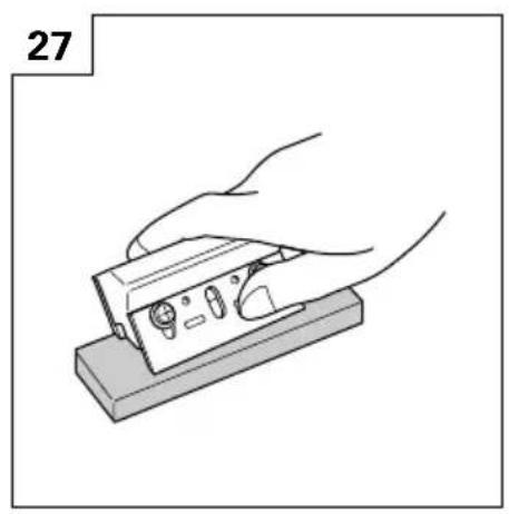
As shown in Fig. 26, two blades can be mounted on the blade sharpening ass'y to ensure that the blade tips are ground at uniform angles. During grinding, adjust the position of the blades so that their edges simultaneously contact the dressing stone as shown in Fig. 27.
2. Blade sharpening intervals
Blade sharpening intervals depend on the type of wood being cut and the cutting depth. However, sharpening should generally be effected after each 500 meters of cutting operation.
3. Dressing Stone
When a water dressing stone is available, use it after dipping it sufficiently in water since such a dressing stone may be worn during grinding works, flatten the upper surface of the dressing stone as often as necessary.
ATTACHING AND DETACHING THE DUST ADAPTER (OPTIONAL ACCESSORY)
CAUTION
To prevent accidents, ensure that the power tool is switched off and the plug is disconnected from the power source.
○Follow the procedure below to mount the dust adapter securely. Failure to do so may result in the adapter coming off, causing injury.
1. Attaching the dust adapter
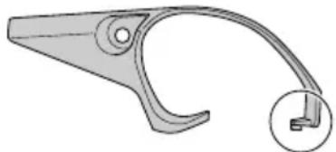
(1) Remove the screw D4 × 16 in the chip cover and remove the chip cover as shown in Fig. 28.
(2) Mount the dust adapter and secure with the screw D4 × 16. (Fig. 29)
NOTE:
Take care not to break the catch when attaching or detaching the dust adapter and chip cover.
natural_image
Technical line drawing of a mechanical clamp or bracket (no text or symbols)2. Removing the dust adapter
To remove the dust adapter, follow the procedure above in reverse order.
MAINTENANCE AND INSPECTION
1. Inspecting the blades
Continued use of dull or damaged blades will result in reduced cutting efficiency and may cause overloading of the motor. Sharpen or replace the blades as often as necessary.
2. Handling
CAUTION
The front base, rear base, and cutting depth control knob are precisely machined to obtain specifically high precision. If these parts are roughly handled or subjected to heavy mechanical impact, it may cause deteriorated precision and reduced cutting performance. These parts must be handled with particular care.
3. Inspecting the mounting screws
Regularly inspect all mounting screws and ensure that they are properly tightened. Should any of the screws be loose, retighten them immediately. Failure to do so could result in serious hazard.
4. Inspecting the carbon brushes (Fig. 30)
The motor employs carbon brushes which are consumable parts. Since an excessively worn carbon brush can result in motor trouble, replace the carbon brushes with new ones having the same carbon brush No. shown in the figure when it becomes worn to or near the "wear limit". In addition, always keep carbon brushes clean and ensure that they slide freely within the brush holders.
5. Replacing carbon brushes
After removing the chip cover, use a slotted screwdriver to disassemble the brush caps. The carbon brushes can then be easily removed with the spring.
6. Maintenance of the motor
The motor unit winding is the very "heart" of the power tool.
Exercise due care to ensure the winding does not become damaged and/or wet with oil or water.
7. Replacing supply cord
If the replacement of the supply cord is necessary, it has to be done by HiKOKI Authorized Service Center to avoid a safety hazard.
8. Service parts list
CAUTION
Repair, modification and inspection of HiKOKI Power Tools must be carried out by a HiKOKI Authorized Service Center.
This Parts List will be helpful if presented with the tool to the HiKOKI Authorized Service Center when requesting repair or other maintenance.
In the operation and maintenance of power tools, the safety regulations and standards prescribed in each country must be observed.
MODIFICATION
HiKOKI Power Tools are constantly being improved and modified to incorporate the latest technological advancements.
Accordingly, some parts may be changed without prior notice.
GUARANTEE
We guarantee HiKOKI Power Tools in accordance with statutory/country specific regulation. This guarantee does not cover defects or damage due to misuse, abuse, or normal wear and tear. In case of complaint, please send the Power Tool, undismantled, with the GUARANTEE CERTIFICATE found at the end of this Handling instruction, to a HiKOKI Authorized Service Center.
NOTE
Due to HiKOKI's continuing program of research and development, the specifications herein are subject to change without prior notice.
IMPORTANT
Correct connection of the plug
The wires of the main lead are coloured in accordance with the following code:
Blue: -- Neutral
Brown: -- Live
As the colours of the wires in the main lead of this tool may not correspond with the coloured markings identifying the terminals in your plug proceed as follows: The wire coloured blue must be connected to the terminal marked with the letter N or coloured black.
The wire coloured brown must be connected to the terminal marked with the letter L or coloured red.
Neither core must be connected to the earth terminal.
NOTE
This requirement is provided according to BRITISH STANDARD 2769: 1984.
Therefore, the letter code and colour code may not be applicable to other markets except The United Kingdom.
Information concerning airborne noise and vibration
The measured values were determined according to EN60745 and declared in accordance with ISO 4871.
Measured A-weighted sound power level: 94 dB (A).
Measured A-weighted sound pressure level: 83 dB (A).
Uncertainty KpA: 3 dB (A).
Wear hearing protection.
Vibration total values (triax vector sum) determined according to EN60745.
Planing softwood:
Vibration emission value a_h=3.1 m/s^2
Uncertainty K = 1.5 m/s ^4
The declared vibration total value has been measured in accordance with a standard test method and may be used for comparing one tool with another.
It may also be used in a preliminary assessment of exposure.
WARNING
○The vibration emission during actual use of the power tool can differ from the declared total value depending on the ways in which the tool is used.
○Identify safety measures to protect the operator that are based on an estimation of exposure in the actual conditions of use (taking account of all parts of the operating cycle such as the times when the tool is switched off and when it is running idle in addition to the trigger time).
natural_image
Technical line drawing of a mechanical bracket or clamp (no text or symbols)natural_image
Technical line drawing of a mechanical clamp or bracket (no text or symbols)natural_image
Technical line drawing of a mechanical clamp or bracket (no text or symbols)VEILIGHEIDSWAARSCHUWINGEN VOOR DE SCHAAF MACHINE
natural_image
Technical line drawing of a mechanical clamp or bracket (no text or symbols)natural_image
Technical line drawing of a mechanical clamp or bracket (no text or symbols)natural_image
Technical line drawing of a mechanical clamp or bracket (no text or symbols)1. Inspeccionar as lâminas
| English | Nederlands | ||
| GUARANTEE CERTIFICATE1Model No.2Serial No.3Date of Purchase4Customer Name and Address5Dealer Name and Address(Please stamp dealer name and address) | GARANTIEBEWIJS1Modelnummer2Serienummer3Datum van aankoop4Naam en adres van de gebruiker5Naam en adres van de handelaar(Stempel a.u.b. naam en adres vande de handelaar) | ||
| Deutsch | Español | ||
| GARANTIESCHEIN1Modell-Nr.2Serien-Nr.3Kaufdaturn4Name und Anschrift des Kunden5Name und Anschrift des Händlers(Bitte mit Namen und Anschrift des Handlers abstempeln) | CERTIFICADO DE GARANTIA1Número de modelo2Número de serie3Fecha de adquisición4Nombre y dirección del cliente5Nombre y dirección del distribudor(Se ruega poner el sello del distribudor con su nombre y dirección) | ||
| Français Português | |||
| CERTIFICAT DE GARANTIE1No. de modèle2No. de série3Date d'achat4Nom et adresse du client5Nom et adresse du revendeur(Cachet portant le nom et l'adresse du revendeur) | CERTIFICADO DE GARANTIA1Número do modelo2Número do série3Data de compra4Nome e morada do cliente5Nome e morada do distribuidor(Por favor, carímbe o nome e morada do distribuidor) | ||
| Italiano | |||
| CERTIFICATO DI GARANZIA1Modello2N° di serie3Data di acquisto4Nome e indirizzo dell'acquirente5Nome e indirizzo del rivenditore(Si prega di apporre il timbro con questi dati) | |||
HiKOKI
| 1 | |
| 2 | |
| 3 | |
| 4 | |
| 5 |
Siemensring 34, 47877 willich, Germany
Tel: +49 2154 49930
Fax: +49 2154 499350
URL: http://www.hikoki-powertools.de
Hikoki Power Tools Netherlands B.V.
Brabanthaven 11, 3433 PJ Nieuwegein, The Netherlands
Tel: +31 30 6084040
Fax: +31 30 6067266
URL: http://www.hikoki-powertools.nl
Hikoki Power Tools (U.K.) Ltd.
Precedent Drive, Rooksley, Milton Keynes, MK 13, 8PJ,
United Kingdom
Tel: +44 1908 660663
Fax: +44 1908 606642
URL: http://www.hikoki-powertools.uk
Hikoki Power Tools France S.A.S.
Hikoki Power Tools Belgium N.V./S.A.
Koningin Astridlaan 51, B-1780 Wemmel, Belgium
Tel: +32 2 460 1720
Fax: +32 2 460 2542
URL http://www.hikoki-powertools.be
Hikoki Power Tools Italia S.p.A
Via Piave 35, 36077, Altavilla Vicentina (VI), Italy
Tel: +39 0444 548111
Fax: +39 0444 548110
URL: http://www.hikoki-powertools.it
Hikoki Power Tools Ibérica, S.A.
C/ Puigbarral, 26-28, Pol. Ind. Can Petit, 08227 Terrassa
(Barcelona), Spain
Tel: +34 93 735 6722
Fax: +34 93 735 7442
URL: http://www.hikoki-powertools.es

- Save all warnings and instructions for future reference.
- 1) Work area safety
- 2) Electrical safety
- 3) Personal safety
- 4) Power tool use and care
- 5) Service
- PLANER SAFETY WARNINGS
- STANDARD ACCESSORIES
- OPTIONAL ACCESSORIES (sold separately)
- APPLICATIONS
- PRIOR TO OPERATION
- PLANING PROCEDURES
- Cord holder
- Stand
- CARBIDE BLADE ASSEMBLY AND DISASSEMBLY AND ADJUSTMENT OF CUTTER BLADE HEIGHT (FOR DOUBLE EDGED BLADE TYPE)
- Carbide blade disassembly
- CAUTION
- Carbide blade assembly
- Adjustment of carbide blade height CAUTION
- BLADE ASSEMBLY AND DISASSEMBLY AND ADJUSTMENT OF BLADE HEIGHT (FOR RESHARPENABLE BLADE TYPE)
- Blade disassembly
- Blade assembly
- Adjustment of blade height
- SHARPENING THE RESHARPENABLE BLADES
- Use of Blade Sharpening Ass'y
- Blade sharpening intervals
- Dressing Stone
- ATTACHING AND DETACHING THE DUST ADAPTER (OPTIONAL ACCESSORY)
- Attaching the dust adapter
- NOTE:
- Removing the dust adapter
- MAINTENANCE AND INSPECTION
- Inspecting the blades
- Handling
- Inspecting the mounting screws
- Inspecting the carbon brushes (Fig. 30)
- Replacing carbon brushes
- Maintenance of the motor
- Replacing supply cord
- Service parts list
- MODIFICATION
- GUARANTEE
- NOTE
- IMPORTANT
- Correct connection of the plug
- Information concerning airborne noise and vibration
- WARNING
- VEILIGHEIDSWAARSCHUWINGEN VOOR DE SCHAAF MACHINE
- Inspeccionar as lâminas
- HiKOKI
- Hikoki Power Tools Netherlands B.V.
- Hikoki Power Tools (U.K.) Ltd.
- Hikoki Power Tools France S.A.S.
- Hikoki Power Tools Belgium N.V./S.A.
- Hikoki Power Tools Italia S.p.A
- Hikoki Power Tools Ibérica, S.A.
Brand : HiKOKI
Model : P20SFWAZ
Category : Plane