
VPLFHZ75 - Projector SONY - Free user manual and instructions
Find the device manual for free VPLFHZ75 SONY in PDF.

| Product type | Laser projector |
| Brand | Sony |
| Model | VPLFHZ75 |
| Display technology | LCD (3LCD) |
| Light source | Laser (laser diodes, wavelength 450-460 nm) |
| Laser class | Class 1 (IEC 60825-1:2014) / Class 3R (United States) |
| Interchangeable lenses | Yes, several optional lenses (VPLL-3007, Z3009, Z3010, Z3024, Z3032, etc.) |
| Lens shift | Motorized, vertical and horizontal (ranges vary by lens) |
| Focus | Motorized or manual depending on lens |
| Zoom | Motorized or manual depending on lens |
| Video inputs | HDMI (INPUT C) and other inputs (A, B, D) |
| Network port | LAN (RJ45) |
| Remote control | Yes, model RM-PJ30, AA batteries (supplied) |
| Included accessories | Remote control, batteries, power cord, plug holder, terminal cover, quick reference guide, CD-ROM user manual |
| Air filter | Cleanable and replaceable |
| Cleaning | Lens: soft cloth; Cabinet: slightly damp soft cloth |
| Safety | Do not look into the lens; avoid direct eye exposure; Class 1/3R laser |
| Installation | Ceiling mounting possible (recommended mount); observe ventilation distances |
| Intelligent Settings function | Yes, with modes: Meeting/classroom, Museum, Entertainment, Multi-screen |
| Browser control | Yes, access to control window via network |
Frequently Asked Questions - VPLFHZ75 SONY
User questions about VPLFHZ75 SONY
0 question about this device. Answer the ones you know or ask your own.
Ask a new question about this device
Download the instructions for your Projector in PDF format for free! Find your manual VPLFHZ75 - SONY and take your electronic device back in hand. On this page are published all the documents necessary for the use of your device. VPLFHZ75 by SONY.
USER MANUAL VPLFHZ75 SONY
© 2019 Sony Corporation


5002991050
このマニュアルについて
natural_image
Line drawing of a portable air conditioner unit emitting steam, with no text or symbols present.natural_image
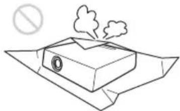
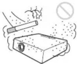
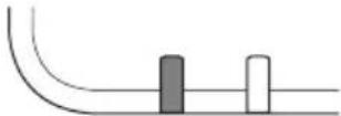
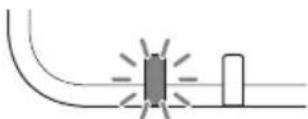
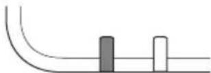
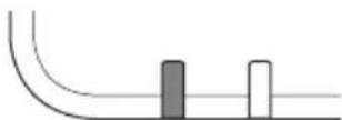
Simple line drawing of a device emitting smoke or vapor, with a prohibition symbol above (no text or labels)熱感知器や煙感知器のそばに設置しない

禁止
natural_image
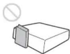
Simple line drawing of a rectangular block with a gray side and a prohibition symbol above it (no text or labels)natural_image
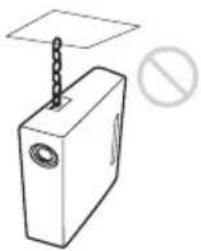
Simple line drawing of a rectangular device with a chain attached to top, and a prohibition symbol (no text or labels)排気口をのぞかない

natural_image
Illustration of a portable stove emitting steam, with a computer and a prohibition symbol (no text or labels)natural_image
Diagram showing airflow around a ventilation duct with a stop symbol (no text or labels)natural_image
Diagram of a kitchen or exhaust system with a bowl, chimney, and exhaust pipe (no text or symbols)natural_image
Illustration of a cigarette emitting smoke next to a smoking tray (no text or symbols)natural_image
Simple line drawing of a mechanical component or tool with no visible text or symbols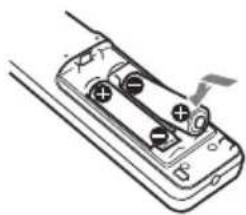
natural_image
Diagram of a battery pack with two terminals and a lightning bolt indicating discharging (no text or symbols)2ふたを閉める。
警告
pie
| Category | Percentage (%) | |---|---| | Top Left | 70 | | Top Right | 32 | | Bottom Left | 32 | | Bottom Right | 5 |$$ \mathrm{VS} _ {+} = 7 0 \quad - 2. 1 8 7 \times (\mathrm{HS} \text {もしくはHS-}) [ \% ] $$
$$ \mathrm{VS} _ {-} = 5 \quad - 0. 1 5 6 \times (\mathrm{HS} \text {もしくは} \quad \mathrm{HS}) [ \% ] $$
$$ \mathrm{HS} _ {+} = 32 - 0.457 \times \mathrm{VS} [\% ] $$
$$ \mathrm{HS} _ {-} = 32 - 6.400 \times \mathrm{VS} [\% ] $$
■ VPLL-Z3024、VPLL-Z3032
pie
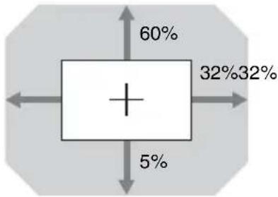
| Category | Percentage (%) | |---|---| | Top Left | 60 | | Bottom Left | 32 | | Bottom Right | 5 | | Top Right | 32 |$$ \mathrm{VS} _ {+} = 6 0 \quad - \quad 1. 8 7 5 \times_ {+} (\mathrm{HS} < \text {は} \quad \mathrm{HS}) [ \% ] $$
$$ \mathrm{VS} _ {-} = 5 \quad - \quad 0. 1 5 6 \times_ {+} (\mathrm{HS} < \text {は} \quad \mathrm{HS}) [ \% ] $$
$$ \mathrm{HS} _ {+} = \mathrm{HS} _ {-} = 3 2 - 0. 5 3 3 \times [ \% ] $$
$$ \mathrm{HS} _ {+} = \mathrm{HS} _ {-} = 3 2 - 6. 4 0 0 \times [ \% ] $$
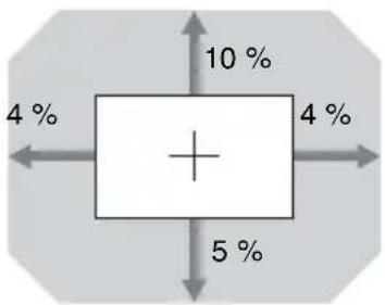
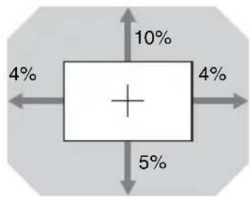
VPLL-3007
boxplot
| Category | Value (%) | |---|---| | Top Left | 4 | | Top Right | 10 | | Bottom Left | 4 | | Bottom Right | 5 | | Bottom Right | 4 |$$ \mathrm{VS} _ {+} = 1 0 \quad - \quad 2. 5 0 0 \times + (\mathrm{HS} < \text {は} \quad \mathrm{HS}) [ \% ] $$
$$ \mathrm{VS} _ {-} = 5 \quad - \quad 1. 2 5 0 \times + (\mathrm{HS} < \text {は} \quad \mathrm{HS}) [ \% ] $$
$$ \mathrm{HS} _ {+} = \mathrm{HS} _ {-} = 4 - 0. 4 0 0 \times [ \% ] $$
$$ \mathrm{HS} _ {+} = \mathrm{HS} _ {-} = 4 - 0. 8 0 0 \times [ \% ] $$
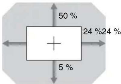
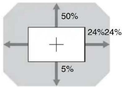
VPLL-Z3009
boxplot
| Quadrant | Value (%) | |---|---| | Top Left | 24 | | Top Right | 50 | | Bottom Left | 5 | | Bottom Right | 24 | | Bottom Center | 5 |$$ \mathrm{VS} _ {+} = 5 0 \quad - \quad 2. 0 8 3 \times_ {+ (\text { HS } < \text { は HS })} [ \% ] $$
$$ \mathrm{VS} _ {-} = 5 \quad - \quad 0. 2 0 8 \times_ {+} (\mathrm{HS} < \text {は} \quad \mathrm{HS}) [ \% ] $$
$$ \mathrm{HS} _ {+} = \mathrm{HS} _ {-} = 2 4 - 0. 4 8 0 \times [ \% ] $$
$$ \mathrm{HS} _ {+} = \mathrm{HS} _ {-} = 2 4 - 4. 8 0 0 \times [ \% ] $$
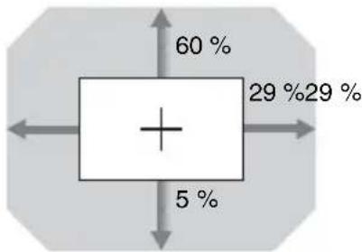
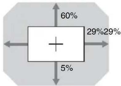
VPLL-Z3010
pie
| Category | Percentage (%) | | :--- | :--- | | Top Left | 60 | | Top Right | 29 | | Bottom Left | 5 | | Bottom Right | 29 |$$ \mathrm{VS} _ {+} = 6 0 \quad - \quad 2. 0 6 9 \times (\text { HSL } < \text { は HS }) [ \% ] $$
$$ \mathrm{VS} _ {-} = 5 \quad - \quad 0. 1 7 2 \times + (\text { HS } \text { < はHS }) [ \% ] $$
$$ \mathrm{HS} _ {+} = \mathrm{HS} _ {-} = 2 9 - 0. 4 8 3 \times \mathrm{VS} [ \% ] $$
$$ \mathrm{HS} _ {+} = \mathrm{HS} _ {-} = 2 9 - 5. 8 0 0 \times [ \% ] $$
電源コードを接続する
natural_image
Diagram of a device with an arrow pointing to a button (no text or symbols present)メニューの表示言語を切り替える
natural_image
Technical line drawing of an electronic device showing internal components and wiring (no text or symbols)ご注意
natural_image
Diagram of a projector with a screw and directional arrows indicating rotation (no text or symbols)ご注意
natural_image
Technical diagram of a mechanical or electrical component with layered structure and directional arrows (no text or symbols)natural_image
Technical line drawing of a mechanical component with circular and curved features (no text or symbols)ご注意
This Quick Reference Manual explains the basic operations for projecting pictures. It also describes important notes and cautions to which you have to pay attention when handling and using this unit.
Refer to “Indicators,” “Cleaning the Air Filter,” and “Replacing the Projection Lens,” as necessary.
For details on the operations, refer to the Operating Instructions contained in the supplied CD-ROM.
Step 1
Preparing ......Page 16
Step 2
Connecting......Page 21
Step 3
Projecting......Page 23
Indicators Page 27
Cleaning the Air Filter ......Page 29
Replacing the Projection Lens......page 30
English
Before operating the unit, please read this manual thoroughly and retain it for future reference.
When using the product, do not use it for purposes other than those described in the instruction manual.
WARNING
To reduce the risk of fire or electric shock, do not expose this apparatus to rain or moisture. To avoid electrical shock, do not open the cabinet. Refer servicing to qualified personnel only.
WARNING
This apparatus must be earthed.
CAUTION
- Danger of explosion if battery is incorrectly replaced. Replace only with the same or equivalent type recommended by the manufacturer.
- When you dispose of the battery or the product, you must obey the law in the corresponding area or country. Do not dispose of the battery or the product in a fire or a hot oven, or mechanically crush or cut the battery. It may explode or cause a fire. Do not subject the battery to extremely low air pressure that may result in an explosion or the leakage of flammable liquid or gas.
- Do not place the battery in a high temperature place, such as under direct sunlight or near fire. It may ignite, explode, or cause a fire. Do not immerse or wet the battery in water or seawater. This may cause an electric shock.
WARNING
When installing the unit, incorporate a readily accessible disconnect device in the fixed wiring, or connect the power plug to an easily accessible socket-outlet near the unit. If a fault should occur during operation of the unit, operate the disconnect device to switch the power supply off, or disconnect the power plug.
CAUTION
For safety, do not connect the connector for peripheral device wiring that might have excessive voltage to the following port:
• LAN terminal
WARNING
- Use the approved Power Cord (3-core mains lead) / Appliance Connector / Plug with earthing-contacts that conforms to the safety regulations of each country/region if applicable.
- Use the Power Cord (3-core mains lead) / Appliance Connector / Plug conforming to the proper ratings (Voltage, Ampere).
If you have questions on the use of the above Power Cord / Appliance Connector / Plug, please consult a qualified service personnel.
IMPORTANT
The nameplate is located in the following location on the unit.
- Bottom
CAUTION
The following size and number of batteries are required for the remote control.
- Size: AA (R6)
• Number of battery(ies): two To avoid risk of explosion, use only the following type of battery.
• Manganese/Alkaline
For the customers in the U.S.A.
This equipment has been tested and found to comply with the limits for a Class A digital device, pursuant to part 15 of the FCC Rules. These limits are designed to provide reasonable protection against harmful interference when the equipment is operated in a commercial environment. This equipment generates, uses and can radiate radio frequency energy and, if not installed and used in accordance with the instruction manual, may cause harmful interference to radio communications. Operation of this equipment in a residential area is likely to cause harmful interference in which case the user will be required to correct the interference at his own expense.
You are cautioned that any changes or modifications not expressly approved in this manual could void your authority to operate this equipment.
Changes or modifications not expressly approved by the party responsible for compliance could void the user's authority to operate the equipment.
All interface cables used to connect the equipment to peripherals must be shielded type to comply with EMC standard(s) and to prevent undesired operation due to radiated emissions. When cables are supplied, always use them for this purpose.
If you have any questions about this product, you may call:
Sony Customer Information Service
Center 1-800-222-7669 or http://
www.sony.com/
Supplier's Declaration of Conformity
Trade Name : SONY
Model : VPL-FHZ75/FHZ70
Responsible party : Sony Electronics Inc.
Address : 16535 Via Esprillo, San Diego, CA 92127 U.S.A.
Telephone : 858-942-2230 Number
This device complies with part 15 of the FCC Rules. Operation is subject to the following two conditions: (1) This device may not cause harmful interference, and (2) this device must accept any interference received, including interference that may cause undesired operation.
For the customers in Canada
CAN ICES-3 (A)/NMB-3(A)
For the customers in Europe, Australia and New Zealand
WARNING
This equipment is compliant with Class A of CISPR 32. In a residential environment this equipment may cause radio interference.
WARNING
Operation of this equipment in a residential environment could cause radio interference.
For the customers in Europe
This apparatus shall not be used in the residential area.
For the customers in the U.S.A.
CAUTION
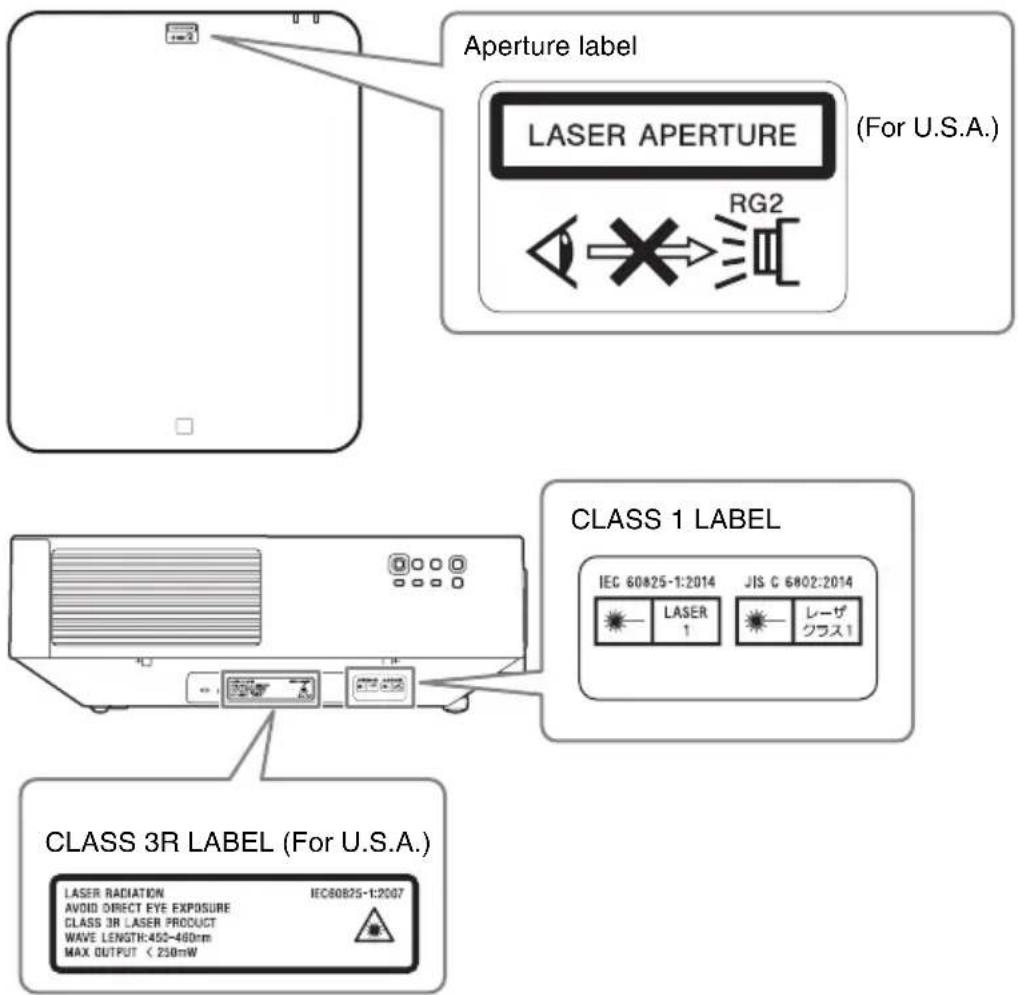
Use of controls or adjustments or performance of procedures other than those specified herein may result in hazardous radiation exposure. This product is classified as a CLASS 3R LASER PRODUCT.
WARNING
LASER RADIATION AVOID DIRECT EYE EXPOSURE CLASS 3R LASER PRODUCT
CAUTION
Do not look into the lens while in use.
CAUTION
Do not allow children to operate this product without supervision.
CAUTION
The use of optical instruments with this product will increase eye hazard.
For the customers in other countries/regions
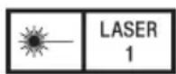
IEC 60825-1:2014 CLASS 1 LASER PRODUCT
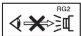
As with any bright light source, do not stare into the beam, RG2 IEC 62471-5:2015.
WARNING: Do not look into the lens while in use.
Caution
Use of controls or adjustments or performance of procedures other than those specified herein may result in hazardous radiation exposure.
Caution
The use of optical instruments with this product will increase eye hazard.
Location information of the labels
Light source specifications
4.35 W laser diodes
× 32 (VPL-FHZ75)
× 28 (VPL-FHZ70)
Wavelength: 450 - 460 nm
Beam divergence angle from lens of this unit
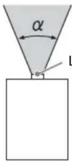
Laser emission port
| Lens Zoom | maximum: α | Zoom minimum: α |
| Standard lens 45 | 3° 29.4° | |
| VPLL-3007 84° | - | |
| VPLL-Z3009 69° | 61° | |
| VPLL-Z3010 61° | 46° | |
| VPLL-Z3024 28° | 21° | |
| VPLL-Z3032 21° | 14° | |
| VPLL-2007 84° | - | |
| VPLL-Z2009 69° | 61° | |
| VPLL-Z1024 28° | 21° | |
| VPLL-Z1032 21° | 14° | |
| VPLL-3003 122° | - |
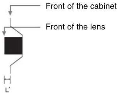
The distance L' between the front of the lens (center) and the front of the cabinet
Unit: mm (inches)
| Lens L' | |
| Standard lens 1.2 ( | ^1/_16 |
| VPLL-3007 52.4 (2 | ^1/_16 |
| VPLL-Z3009 51.2 (2 | ^1/_32 |
| VPLL-Z3010 60 (2 | ^3/_8 |
| VPLL-Z3024 9.9 ( | ^3/_8 |
| VPLL-Z3032 9.9 ( | ^3/_8 |
| VPLL-2007 52.4 (2 | ^1/_16 |
| VPLL-Z2009 51.2 (2 | ^1/_32 |
| VPLL-Z1024 9.9 ( | ^3/_8 |
| VPLL-Z1032 9.9 ( | ^3/_8 |
| VPLL-3003 256 (10 | ^3/_32 |
For the Customers in Brazil only
For the customers in the U.S.A. SONY LIMITED WARRANTY - Please visit http://www.sony.com/psa/warranty for important information and complete terms and conditions of Sony's limited warranty applicable to this product.
For the customers in Canada SONY LIMITED WARRANTY - Please visit http://www.sonybiz.ca/pro/lang/en/ca/article/resources-warranty for important information and complete terms and conditions of Sony's limited warranty applicable to this product.
For the customers in Europe
Sony Professional Solutions Europe - Standard Warranty and Exceptions on Standard Warranty. Please visit https://pro.sony/support-services/primesupport/support-professional-solutions-europe-standard-product-warranty for important information and complete terms and conditions.
For the customers in Korea SONY LIMITED WARRANTY - Please visit http://bpeng.sony.co.kr/handler/BPAS-Start for important information and complete terms and conditions of Sony's limited warranty applicable to this product.
For the customers in Taiwan only
第一類雷射產品

廢電池請回收
- Check that the operating voltage of your unit is identical with the voltage of your local power supply. If voltage adaptation is required, consult with qualified Sony personnel.
- Should any liquid or solid object fall into the cabinet, unplug the unit and have it checked by qualified Sony personnel before operating it further.
- Unplug the unit from the wall outlet if it is not to be used for several days.
• To disconnect the cord, pull it out by the plug. Never pull the cord itself.
- The wall outlet should be near the unit and easily accessible.
- The unit is not disconnected from the AC power source (mains) as long as it is connected to the wall outlet, even if the unit itself has been turned off.
- Do not look into the lens while in use.
- When turning on the projector, make sure no one is peeking at the projection lens.
- Do not let children use the unit alone.
- Do not place your hand or objects near the ventilation holes — the air coming out is hot.
- Be careful not to catch your fingers by the feet (adjustable) when you adjust the height of the unit. Do not push hard on the top of the unit with the adjuster out.
- Be sure to use two people to grasp both sides of the unit when carrying the unit.
- Avoid using an extension cord with a low voltage limited since it may cause the short-circuit and physical incidents.
- Do not catch your finger between the unit and surface of the floor when moving the projector installed on the floor.
- Be careful not to catch your finger in the cooling fan.
- Do not carry the projector with the cabinet on and with its cover open.
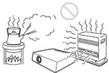
- Do not install the unit in a location near heat sources such as radiators or air ducts, or in a place subject to direct sunlight, excessive dust or humidity, mechanical vibration or shock.
- If a user disassembles, repairs, or alters the unit, it may cause a serious problem to the user's safety.
- If the projector malfunctions or is damaged, consult with a qualified Sony personnel.
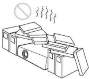
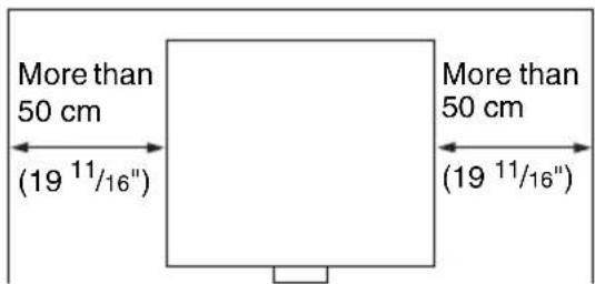
- If the ventilation holes are blocked, internal heat builds up, and it may cause a fire or damage the unit. To allow adequate air circulation and prevent internal heat build-up, follow the items below:
- Place the unit, leaving sufficient space from walls or any objects (page 13).
natural_image
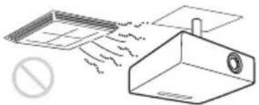
Line drawing of a cluttered industrial machine with smokestacks emitting vapor (no text or symbols)- Avoid using something to cover the ventilation holes (exhaust/intake).
natural_image
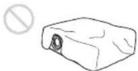
Simple line drawing of a rectangular object with a circular opening and a prohibition symbol (no text or labels)- Do not place the unit on surfaces such as an original packing sheet, soft cloth, papers, rugs, or scraps of paper. The ventilation holes may take in such materials.
natural_image
Simple line drawing of a chimney on a roof with smoke and a prohibition symbol (no text or labels)- Do not place any object in front of the lens that may block the light during projection. Heat from the light may damage the object. Use the picture muting function to cut off the picture.
natural_image
Simple 3D diagram of a rectangular block with a shaded side and a prohibition symbol above it (no text or labels)- Do not use the Security bar for the purpose of preventing theft for transporting or installing the unit. If you lift the unit by the Security bar or hang the unit by this bar, it may cause the unit to fall and be damaged, and may result in personal injury.
natural_image
Simple line drawing of a rectangular device with a chain and a plate, no text or symbols present.- Make sure to remove the protective packaging lens cap before projection. Projection with the cap attached may melt the cap by heat.
For dealers
- When the projector is mounted on the ceiling, a Sony bracket or recommended equivalent must be used for installation.
- Be sure to secure the cabinet cover firmly when installing to the ceiling firmly.
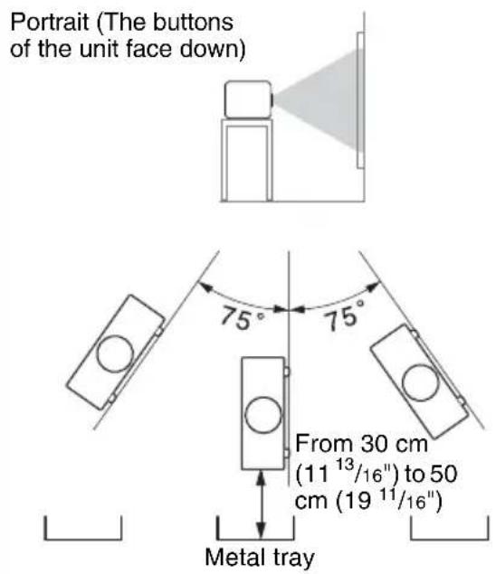
Caution
When installing the unit at the angle illustrated, if the ventilation holes are facing down, install a metal tray (min. 70 cm × 40 cm (27 ^9 /16" × 15 ^3 /4")) at the distance indicated below directly under the ventilation holes.
Ensure that foreign materials or liquids do not drop into the ventilation holes.
Safety precautions for installing the unit on a ceiling
- Never mount the projector on the ceiling or move it by yourself. Be sure to consult the store where you purchased the projector or a dedicated installer.
- When installing the unit on a ceiling, be sure to use a safety wire, etc., to prevent the unit from falling. For the installation, be sure to consult the store where you purchased the projector or a dedicated installer.
On Installation
- When installing the unit, leave space between any walls, etc. and the unit as illustrated.
- Avoid using the unit in a location where the temperature or humidity is very high, or temperature is very low.
natural_image
Illustration of a portable stove emitting smoke next to a printer and a CRT monitor, with a prohibition symbol above (no text or labels)- Avoid installing the unit in a location subject to direct cool or warm air from an air-conditioner. Installing in such a location may cause malfunction of the unit due to moisture condensation or rise in temperature.
natural_image
Diagram showing airflow around a ventilation grille and a 3D structure with a pipe outlet (no text or symbols)- Avoid installing the unit in a location near a heat or smoke sensor. Installing in such a location may cause malfunction of the sensor.
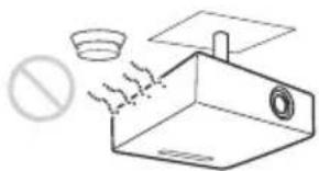
- Avoid installing the unit in a very dusty or extremely smoky environment. Otherwise, the air filter will become obstructed, and this may cause a malfunction of the unit or damage it.
natural_image
Illustration of a cigarette being dispensed from a box with smoke, no text or symbols present- When using the unit at an altitude of 1,500 m or higher, set “High Altitude Mode” to “On” in the Installation menu. Failing to set this mode when using the unit at high altitudes could have adverse effects, such as reducing the reliability of certain components.
- Set “Installation Attitude” on the Installation menu correctly to suit to the Installation angle. Continuing to use the wrong setting may affect component reliability.
On cleaning the lens and the cabinet
- Be sure to disconnect the AC power cord from the AC outlet before cleaning.
- If you rub on the unit with a stained cloth, the cabinet may be scratched.
- If the unit is exposed to volatile materials such as insecticide, or the unit is in contact with a rubber or vinyl resin product for a long period of time, the unit may deteriorate or the coating may come off.
- Do not touch the lens with bare hands.
- On cleaning the lens surface: Wipe the lens gently-with a soft cloth, such as a glass cleaning cloth. Stubborn stains may be removed with a soft cloth lightly dampened with water. Never use solvent such as alcohol, benzene or thinner, or acid, alkaline or abrasive detergent, or a chemical cleaning cloth.
- On cleaning the cabinet: Clean the cabinet gently with a soft cloth. Stubborn stains may be removed with a soft cloth lightly dampened with mild detergent solution and wrung, followed by wiping with a soft dry cloth. Never use solvent such as alcohol, benzene or thinner, or acid, alkaline or abrasive detergent, or a chemical cleaning cloth.
On Illumination
To obtain the best picture, the front of the screen should not be exposed to direct lighting or sunlight.
On Heat Dissipation
The temperature of the projector cabinet may increase during or immediately after use; however, this is not a malfunction.
On Screen
When using a screen with an uneven surface, stripes pattern may rarely appear on the screen depending on the distance between the screen and the unit or the zooming magnifications. This is not a malfunction of the unit.
On Fan
Since the projector is equipped with a fan inside to prevent internal temperature from rising, there may be some noise. This is a normal result of the manufacturing process and does not indicate a malfunction. If, however, in a case of abnormal noise, consult with qualified Sony personnel.
About Lens Replacement
When the power is connected, do not attach or remove the projection lens. Do not attach any lens other than the specified accessory lens sold separately.
On inspection of light source related parts
Since the unit uses a laser, when performing maintenance or inspection of light source related parts, particular attention and a safe environment are necessary. Be sure to consult with qualified Sony personnel.
On disposing used products
Do not dispose the used products and general garbage together. Correctly dispose of used products to avoid harming the environment or the health of yourself and others. Follow the disposal regulations of your area.
On LCD Projector
The LCD projector is manufactured using high-precision technology. You may, however, see tiny black points and/or bright points (red, blue, or green) that continuously appear on the LCD projector. This is a normal result of the manufacturing process and does not indicate a malfunction. Also, when you use multiple LCD projectors to project onto a screen, even if they are of the same model, the color reproduction among projectors may vary, since color balance may be set differently from one projector to the next.
On condensation
If the room temperature where the projector is installed changes rapidly, or if the projector is moved suddenly from a cold to a warm place, condensation in the projector may occur. As the condensation may cause malfunction, be careful in adjusting temperature settings of the air conditioner. If condensation occurs, leave the projector turned on for about two hours before use.
Notes on security
- SONY WILL NOT BE LIABLE FOR DAMAGES OF ANY KIND RESULTING FROM A FAILURE TO IMPLEMENT PROPER SECURITY MEASURES ON TRANSMISSION DEVICES, UNAVOIDABLE DATA LEAKS RESULTING FROM TRANSMISSION SPECIFICATIONS, OR SECURITY PROBLEMS OF ANY KIND.
- Depending on the operating environment, unauthorized third parties on the network may be able to access the unit. When connecting the unit to the network, be sure to confirm that the network is protected securely.
- From a safety standpoint, when using the unit connected with the network, it is strongly recommended to access the Control window via a Web browser and change the access limitation settings from the factory preset values (refer to “Using Network Features” in the Operating Instructions).
Changing the password regularly is also recommended.
- Do not browse any other website in the Web browser while making settings or after making settings. Since the login status remains in the Web browser, close the Web browser when you complete the settings to prevent unauthorized third parties from using the unit or harmful programs from running.
Notes
• Always verify that the unit is operating properly before use. SONY WILL NOT BE LIABLE FOR DAMAGES OF ANY KIND INCLUDING, BUT NOT LIMITED TO, COMPENSATION OR REIMBURSEMENT ON ACCOUNT OF THE LOSS OF PRESENT OR PROSPECTIVE PROFITS DUE TO FAILURE OF THIS UNIT, EITHER DURING THE WARRANTY PERIOD OR AFTER EXPIRATION OF THE WARRANTY, OR FOR ANY OTHER REASON WHATSOEVER.
- SONY WILL NOT BE LIABLE FOR CLAIMS OF ANY KIND MADE BY USERS OF THIS UNIT OR MADE BY THIRD PARTIES.
- SONY WILL NOT BE LIABLE FOR THE TERMINATION OR DISCONTINUATION OF ANY SERVICES RELATED TO THIS UNIT THAT MAY RESULT DUE TO CIRCUMSTANCES OF ANY KIND.
Checking the Supplied Accessories
RM-PJ30 Remote Commander (1)
Size AA (R6) batteries (2)
AC power cord (1)
Plug holder (1)
Terminal cover (1)
Quick Reference Manual (this manual) (1)
Operating Instructions (CD-ROM) (1)
Using the CD-ROM manual
The manual can be read on a computer with Adobe Reader installed.
You can download Adobe Reader free from the Adobe website.
1 Open the index.html file in the CD-ROM.
2 Select and click on the manual that you want to read.
Note
If you have lost or damaged the CD-ROM, you can purchase a new one from your Sony dealer or Sony service counter.
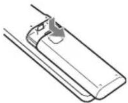
Installing batteries
1 Remove the lid, then install the two AA (R6) batteries (supplied) with the correct polarity.
While pressing the lid, slide it.
Be sure to install the battery from the ⊖ side.
natural_image
Technical line drawing of a mechanical component or assembly (no text or symbols)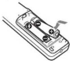
natural_image
Diagram of a handheld battery with two charging leads and a switch, no text or symbols present2 Replace the lid.
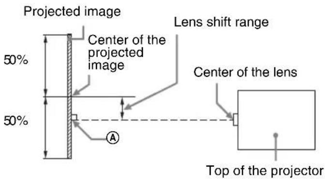
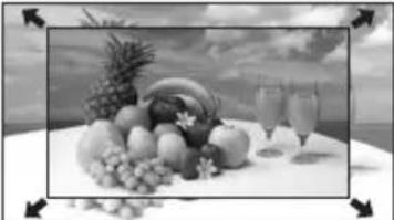
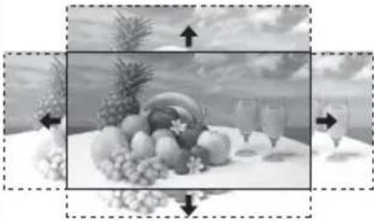
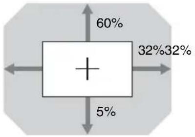
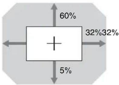
Projection Distance and Lens Shift Range
The projection distance refers to the distance between the front of the lens and the projected surface.
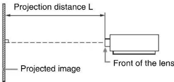
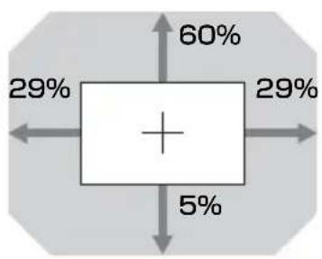
The lens shift range represents the distance in percent (\%) by which the lens can be shifted from the center of the projected image. The lens shift range is regarded as 0% when the point (A) in the illustration (point where a line drawn from the center of the lens and the projected image cross at right angles) is aligned with the center of the projected image and full width or full height of the projected image is regarded as 100% .
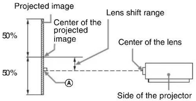
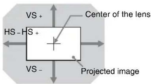
Shaded region: Lens shift range
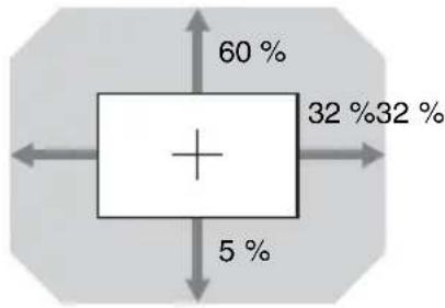
VS+: Vertical lens shift range (up) [%]
VS-: Vertical lens shift range (down) [%]
HS+: Horizontal lens shift range (right) [%]
HS -: Horizontal lens shift range (left) [%]
Projection distance
Unit: m (inches)
| Projection image size Projection distance L | ||||
| Diagonal | Width × Height | Standard lens | VPLL-3007 | VPLL-Z3009 |
| 80" (2.03 m) 1.72 | × 1.08(68 × 42) | 2.36 – 3.86(93 – 152) | 1.09(43) | 1.44 – 1.69(57 – 66) |
| 100" (2.54 m) 2.15 | × 1.35(85 × 53) | 2.96 – 4.84(117 – 191) | 1.38(54) | 1.82 – 2.13(72 – 84) |
| 120" (3.05 m) 2.58 | × 1.62(102 × 64) | 3.57 – 5.82(141 – 229) | 1.67(66) | 2.20 – 2.57(87– 101) |
| 150" (3.81 m) 3.23 | × 2.02(127 × 79) | 4.47 – 7.29(176 – 287) | 2.11(83) | 2.76 – 3.23(109 – 127) |
| 200" (5.08 m) 4.31 | × 2.69(170 × 106) | 5.97 – 9.73(235 – 383) | 2.83(112) | 3.70 – 4.34(146 – 170) |
| Projection image size | Projection distance L | ||
| Diagonal VPLL-Z3010 VPLL-Z3024 | VPLL-Z3032 | ||
| 80" (2.03 m) 1.69 | -2.37(67 - 93) | 4.00 - 5.48(158 - 215) | 5.45 - 8.32(215 - 327) |
| 100" (2.54 m) 2.13 | -2.98(84 - 117) | 5.03 - 6.87(198 - 270) | 6.84 - 10.43(270 - 410) |
| 120" (3.05 m) 2.56 | -3.59(101 - 141) | 6.05 - 8.27(238 - 325) | 8.24 - 12.55(325 - 494) |
| 150" (3.81 m) 3.22 | -4.50(127 - 177) | 7.59 - 10.36(299 - 408) | 10.33 - 15.72(407 - 619) |
| 200" (5.08 m) 4.31 | -6.03(170 - 237) | 10.15 - 13.85(400 - 545) | 13.82 - 21.00(544 - 827) |
Projection distance formula
D: Projection image size (")
Example) Enter 80 in D for the 80" projection image size. Unit: m (inches)
| Lens | Projection distance L (minimal length) | Projection distance L (maximal length) |
| Standard lens L = 0.030040 × D - 0.0443(L = 1.182677 × D - 1.7457) | L = 0.048910 × D - 0.0442(L = 1.925591 × D - 1.7394) | |
| VPLL-3007 | L = 0.014518 × D - 0.0700(L = 0.571579 × D - 2.7563) | - |
| VPLL-Z3009 | L = 0.018832 × D - 0.0678(L = 0.741408 × D - 2.6702) | L = 0.022017 × D - 0.0635(L = 0.866824 × D - 2.4985) |
| VPLL-Z3010 | L = 0.021850 × D - 0.0631(L = 0.860217 × D - 2.4830) | L = 0.030491 × D - 0.0640(L = 1.200444 × D - 2.5211) |
| VPLL-Z3024 | L = 0.051187 × D - 0.0973(L = 2.015234 × D - 3.8296) | L = 0.069717 × D - 0.0930(L = 2.744761 × D - 3.6617) |
| VPLL-Z3032 | L = 0.069792 × D - 0.1414(L = 2.747720 × D - 5.5654) | L = 0.105707 × D - 0.1323(L = 4.161687 × D - 5.2083) |
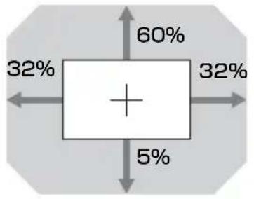
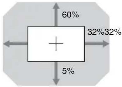
Lens shift range
Standard lens
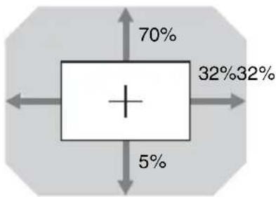
pie
| Category | Percentage (%) | |---|---| | Top Left | 70 | | Top Right | 32 | | Bottom Left | 5 | | Bottom Right | 32 |$$ \mathrm{VS} _ {+} = 70 - 2.187 \times (\mathrm{HS} + \text { or } \mathrm{HS} -) [\% ] $$
$$ \mathrm{VS} _ {-} = 5 - 0.156 \times (\mathrm{HS} + \text { or } \mathrm{HS} _ {-}) [\% ] $$
$$ \mathrm{HS} _ {+} = 32 - 0.457 \times \mathrm{VS} + [ \% ] $$
$$ \mathrm{HS} - = 32 - 6.400 \times \mathrm{VS} - [\% ] $$
■ VPLL-Z3024, VPLL-Z3032
pie
| Category | Percentage (%) | |---|---| | Top Left | 60 | | Top Right | 32 | | Bottom Left | 5 | | Bottom Right | 32 |$$ \mathrm{VS} _ {+} = 60 - 1.875 \times (\mathrm{HS} _ {+} \text { or } \mathrm{HS} _ {-}) [ \% ] $$
$$ \mathrm{VS} _ {-} = 5 - 0. 1 5 6 \times (\mathrm{HS} + \text { or } \mathrm{HS} _ {-}) [ \% ] $$
$$ \mathrm{HS} _ {+} = \mathrm{HS} _ {-} = 32 - 0.533 \times \mathrm{VS} _ {+} [ \% ] $$
$$ \mathrm{HS} _ {+} = \mathrm{HS} _ {-} = 32 - 6.400 \times \mathrm{VS} _ {-} [ \% ] $$
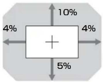
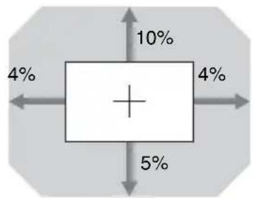
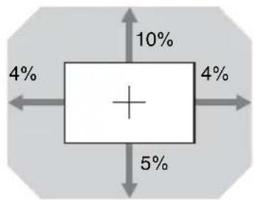
■ VPLL-3007

boxplot
| Value (%) | |---| | 10 | | 5 | | 4 |$$ \mathrm{VS} _ {+} = 10 - 2.500 \times (\mathrm{HS} _ {+} \text {or HS} _ {-}) [ \% ] $$
$$ \mathrm{VS} - = 5 - 1.250 \times (\mathrm{HS} + \text { or } \mathrm{HS} -) [\% ] $$
$$ \mathrm{HS} _ {+} = \mathrm{HS} _ {-} = 4 - 0. 4 0 0 \times \mathrm{VS} + [ \% ] $$
$$ \mathrm{HS} _ {+} = \mathrm{HS} _ {-} = 4 - 0. 8 0 0 \times \mathrm{VS} - [ \% ] $$
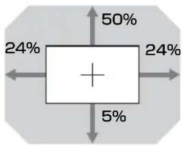
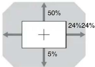
VPLL-Z3009
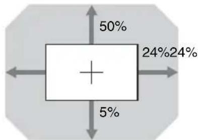
pie
| Category | Percentage (%) | |---|---| | Top Left | 50 | | Top Right | 24 | | Bottom Left | 5 | | Bottom Right | 24 |$$ \mathrm{VS} _ {+} = 50 - 2.083 \times (\mathrm{HS} + \text { or } \mathrm{HS} -) [\% ] $$
$$ \mathrm{VS} - = 5 - 0.208 \times (\mathrm{HS} + \text { or } \mathrm{HS} -) [\% ] $$
$$ \mathrm{HS} _ {+} = \mathrm{HS} _ {-} = 24 - 0.480 \times \mathrm{VS} _ {+} [ \% ] $$
$$ \mathrm{HS} _ {+} = \mathrm{HS} _ {-} = 24 - 4.800 \times \mathrm{VS} _ {-} [ \% ] $$
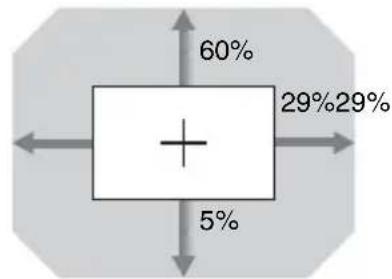
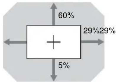
■ VPLL-Z3010

pie
| Category | Percentage (%) | |---|---| | Top Left | 60 | | Top Right | 29 | | Bottom Left | 5 | | Bottom Right | 29 |$$ \mathrm{VS} _ {+} = 6 0 - 2. 0 6 9 \times (\mathrm{HS} + \text { or } \mathrm{HS} -) [ \% ] $$
$$ \mathrm{VS} - = 5 - 0.172 \times (\mathrm{HS} + \text { or } \mathrm{HS} -) [\% ] $$
$$ \mathrm{HS} _ {+} = \mathrm{HS} _ {-} = 29 - 0.483 \times \mathrm{VS} _ {+} [ \% ] $$
$$ \mathrm{HS} _ {+} = \mathrm{HS} _ {-} = 2 9 - 5. 8 0 0 \times \mathrm{VS} _ {-} [ \% ] $$
Connecting the AC Power Cord
1 Plug the AC power cord into the AC IN socket, then attach the plug holder to the AC power cord.
Plug holder (supplied)
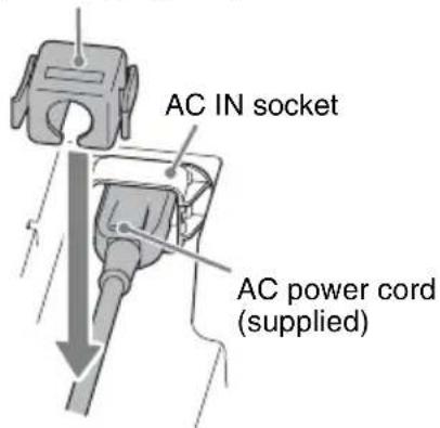
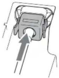
2 Slide the plug holder over the AC power cord to fix to the unit.
natural_image
Simple line drawing of a mechanical component with an arrow indicating direction (no text or symbols)Selecting the Menu Language
The factory setting for the language for displaying menus, messages, etc. is English. To change the on-screen language, proceed as follows:
1 Plug the AC power cord into a wall outlet.
2 Turn on the projector.
Press the I/↓ key on the main unit or the
I key on the Remote Commander.
3 Press the MENU key to display the menu.
If the display cannot be properly seen, adjust the focus, size, and position of the projected image (page 24).
4 Select the menu language.
① Press the ↑ or ↓ key to select the Operation ( ☐ menu then press the ENTER key.
② Press the or key to select "Language (A) then press the ENTER key.
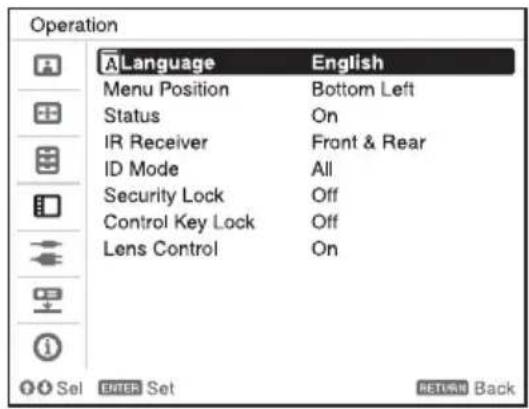
③ Press the /// key to select a language, then press the ENTER key.
5 Press the MENU key to turn off the menu screen.
Notes
- Turn off all equipment before making any connections.
- Use the proper cables for each connection.
- Insert the cable plugs firmly; Loose connections may reduce performance of picture signals or cause a malfunction. When pulling out a cable, be sure to grip it by the plug, not the cable itself.
- For more information, refer also to the instruction manuals of the equipment you are connecting.
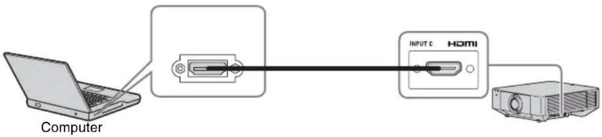
Connecting a Computer
Notes
- Use HDMI-compatible equipment which has the HDMI Logo.
- Use a high speed HDMI cable(s) on which the cable type logo is specified. (Sony products are recommended.)
- The HDMI terminal of this projector is not compatible with DSD (Direct Stream Digital) signal or CEC (Consumer Electronics Control) signal.
For information on other connecting methods, refer to "Connecting the Projector" in the Operating Instructions contained in the supplied CD-ROM.
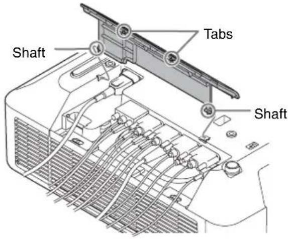
Attaching the terminal cover
You can attach the supplied terminal cover to prevent dust from entering the terminals to maintain a neat appearance.
1 Fit one shaft on the side of the terminal cover into the hole on the bottom, then fit the other shaft by bending the cover slightly.
2 Close the terminal cover.
Close the terminal cover until the two tabs on the terminal cover click.
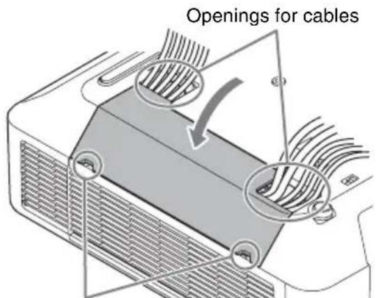
Finger hooks
Example of the cable layout in the cover
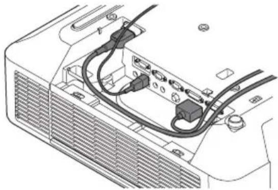
natural_image
Technical line drawing of an electrical connector with visible wiring and mounting points (no text or symbols)Note
The terminal cover may not be attached depending on the installation method, such as due to the condition of the connected cables or when installing the unit on the floor. However, this has no impact on normal use.
Opening the terminal cover
Raise the cover by inserting your fingers into the finger hooks.
Projecting an Image
The size of a projected image depends on the distance between the projector and screen. Install the projector so that the projected image fits the screen size.
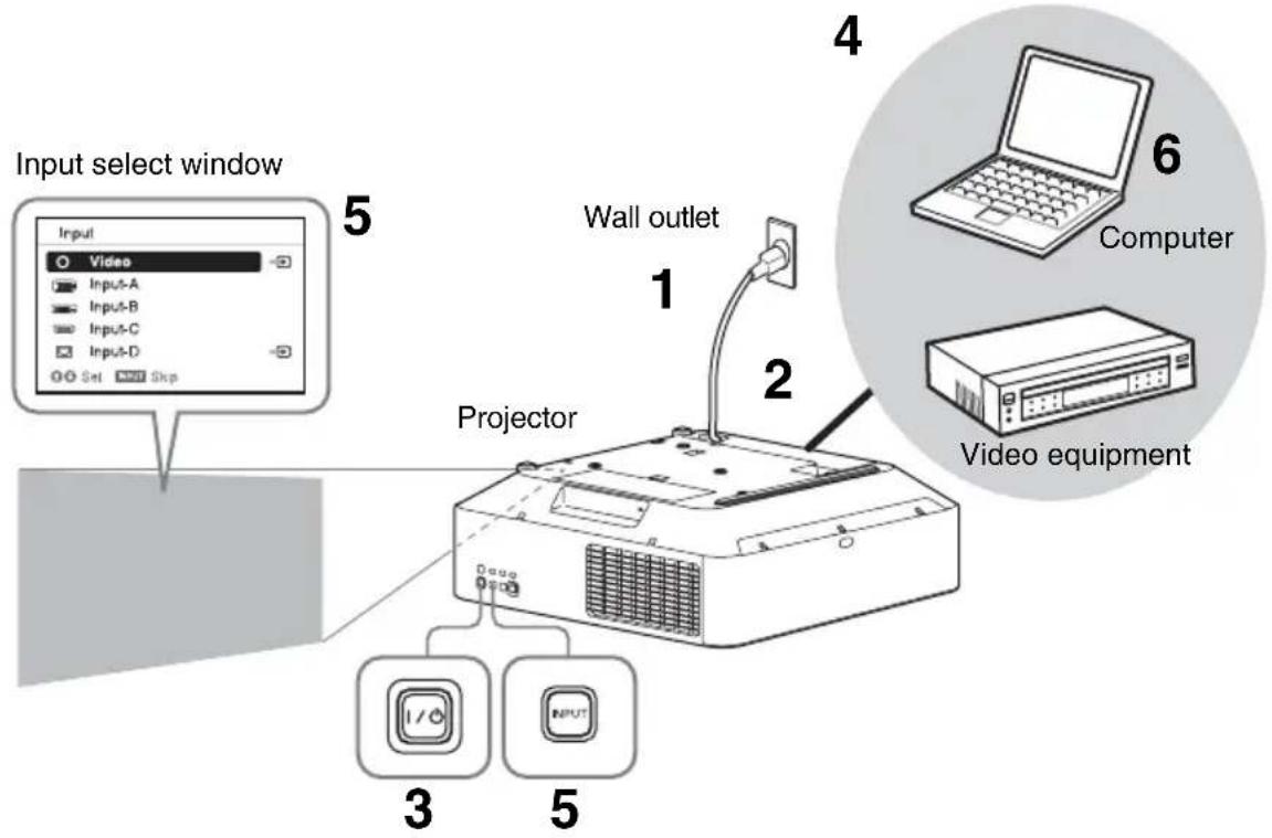
1 Plug the AC power cord into a wall outlet.
2 Connect all equipment to the projector (page 21).
3 Turn on the projector.
Press the I/⏻ key on the main unit or the
I key on the Remote Commander.
4 Turn on the connected equipment.
5 Select the input source.
Press the INPUT key on the projector to display the input select window. Press the INPUT key repeatedly or the ↑/↓ key to select an image to be projected. The signal icon appears on the right side in the input select window when a signal is input.
You can select the input source using Direct input select keys on the Remote Commander.
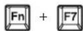
6 Switch your computer to output to external display by changing your computer's setting.
How to switch the computer to output to the projector varies, depending on the type of computer.
(Example)
7 Adjust the focus, size, and position of the projected image.
Adjusting the Focus, Size, and Position of the Projected Image
| Focus Size (Zoom) | Position (Lens shift) | |
 ↓ ↓ |  |  |
When attaching the Electric focus lensPress the FOCUS key on the projector or the Remote Commander then press the ◆/↓/↔/→key to adjust the focus.When attaching the Manual focus lensTurn the focus lever and peripheral focus ring to adjust the focus.You can adjust the focus of the peripheral area by rotating the peripheral focus ring.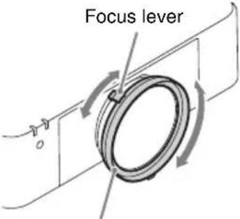 Peripheral focus ring Peripheral focus ring | When attaching the Electric zoom lensPress the ZOOM key on the projector or the Remote Commander then press the ◆/↓/↔/→key to adjust the size.When attaching the Manual zoom lensTurn the zoom lever to adjust the size.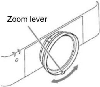 | Press the LENS SHIFT/SHIFT key on the projector or the Remote Commander then press the ◆/↓/↔/→key to adjust the position.To return the lens to the center position of the projected imagePress the RESET key on the Remote Commander while adjusting. |
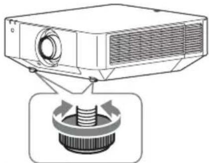
Adjusting the tilt of the projector with the front feet (adjustable)
When the projector is installed on an uneven surface, you can adjust using the front feet (adjustable).
natural_image
Diagram of a projector with a button and arrow indicating rotation (no text or symbols)Notes
- Be careful not to let the projector down on your fingers.
- Do not push hard on the top of the projector with the front feet (adjustable) extended. It may cause a malfunction.
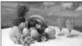
Displaying a pattern for adjusting an image
You can display a pattern for adjusting the projected image with the PATTERN key on the Remote Commander. Use / to change the pattern and / to change its color. Press the PATTERN key again to restore the previous image.
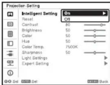
Automatically Optimizing Projector Settings
When you set “Intelligent Setting” to “On” in the Projection Setting menu, you can optimize the picture settings, light settings, and system cooling performance (fan rotation speed) by selecting the installation location from “Location” according to the environment in which the projector is used. “Intelligent Setting” is for stable and prolonged use of the projector.
1 Press the MENU key to display the menu.
2 Set "Intelligent Setting" to "On" in the Projection Setting menu, then press the ENTER key.
3 Select usage location of the projector from the following options.
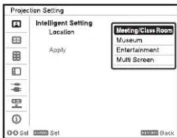
Meeting/Class Room: Sharply projects text and graphics. This is suitable for use in meeting rooms or classrooms.
Museum: Precisely reproduces colors. This is suitable for use in quiet places, such as galleries or museums.
Entertainment: Produces well-contrasted pictures. This is suitable for use at theme parks, public entertainment facilities, conference rooms in the exhibition hall, and so on.
Multi Screen: This is suitable when simultaneously using multiple projectors for projections, such as blending projections or projections from multiple projectors set up side-by-side.
4 Select "Apply," then press the ENTER key.
Turning Off the Power
1 Press the I/⏻ key on the main unit or the ⏻ key on the Remote Commander.
The projector starts shutdown and turns off.
For long-term use, turn off the projector when not in use.
2 Unplug the AC power cord from the wall outlet.
If you need to further adjust projected images, refer to “Projecting/Adjusting an Image” in the Operating Instructions contained in the supplied CD-ROM.
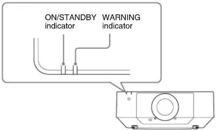
Indicators
You can check the projector status or abnormality by checking the lighting/flashing status of the ON/STANDBY indicator and WARNING indicator on the front. If the indicators flash in red, address the problem in accordance with “Warning indicators and remedies” (page 28).
Operating status indication
| Indicator status Operating status Meaning | ||
 (Off)(Lights in red) (Off)(Lights in red) | Standby The power is supplied to the projector and the projector is in a standby mode according to the setting. | |
 (Off)(Flashes in green) (Off)(Flashes in green) | Warm-up The projector is warming up after it is turned on. | |
 (Off)(Lights in green) (Off)(Lights in green) | Power on The projector is ready for projection. | |
 (Off)(Lights in orange) (Off)(Lights in orange) | Other standby status | The projector is in With No Input (Light Cutoff), or Quick Reboot standby mode. |
Warning indicators and remedies
| Indicator status The number of flashes | Meaning Remedies | |
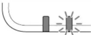 (Lights (Flashes in red) in red) (Lights (Flashes in red) in red) | Twice The side cover or air filter is not installed securely. | Check how the side cover or air filter is attached and install it securely. |
| Three times The light source does not light properly. | Unplug the AC power cord and make sure the ON/STANDBY indicator turns off, then plug the AC power cord into the wall outlet and turn on the projector. | |
| Six times A strong shock to the projector is detected. | If there is no visible abnormality, unplug the AC power cord and make sure the ON/STANDBY indicator turns off, then plug the AC power cord into the wall outlet and turn on the projector. | |
| Eight times The lens is not securely attached. | Check how the lens is attached and install it securely. | |
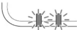 (Flashes (Flashes in red) in red)Both indicators flash (Flashes (Flashes in red) in red)Both indicators flash | Twice The temperature in the projector is abnormal. | · Check if the air filter is clogged, then clean or replace it (page 29). · Check if the ventilation holes (intake/exhaust) are not blocked by the wall or an object and secure a sufficient gap. · Check the ambient temperature and use the projector within the range of operating temperature. |
If the indicators flash in a manner other than described above, unplug the AC power cord and make sure the ON/STANDBY indicator turns off, then plug the AC power cord into the wall outlet and turn on the projector.
If the problem still persists, consult with qualified Sony personnel.
If there is any problem or an error message appears on the screen, refer to “Messages List” or “Troubleshooting” in the Operating Instructions contained in the supplied CD-ROM.
Cleaning the Air Filter
When the message that prompts cleaning the air filter appears, clean the air filter. If the dust cannot be removed from the air filter even after cleaning, replace the air filter with a new one. For details on a new air filter, consult with qualified Sony personnel.
Caution
If you continue to use the projector even after the message is displayed, dust may accumulate, clogging it. As a result, the temperature may rise inside the unit, leading to a possible malfunction or fire.
1 Turn off the projector and disconnect the AC power cord from a wall outlet.
2 Slide the lock switch on the side cover toward UNLOCK to unlock the cover.
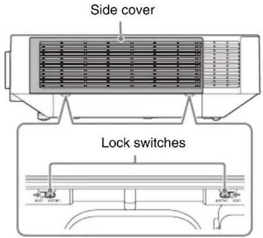
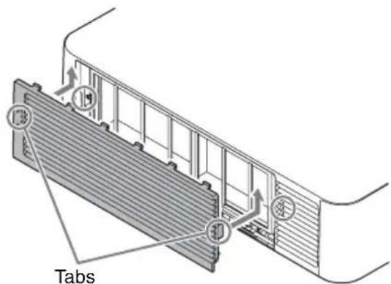
3 Slide the side cover downward by pushing its upper corners on both sides to remove the side cover.
natural_image
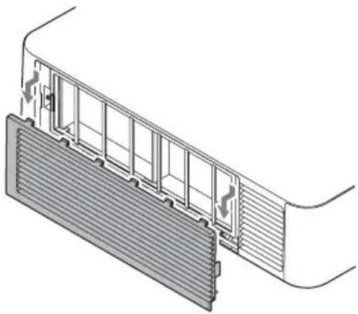
Technical diagram of a mechanical or electrical component with internal structure and heat flow arrows (no text or symbols)4 Loosen the screws (four) and pull out the filter cover by pinching the grab on the left side.
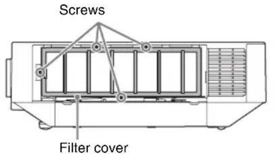
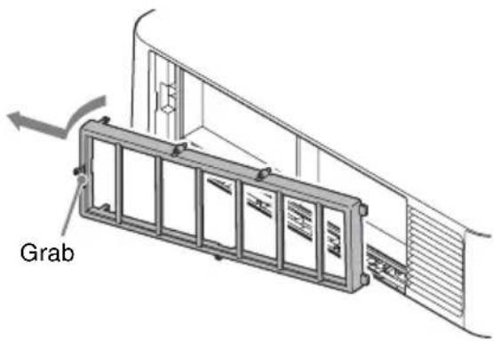
5 Pull out the air filter from the main unit.
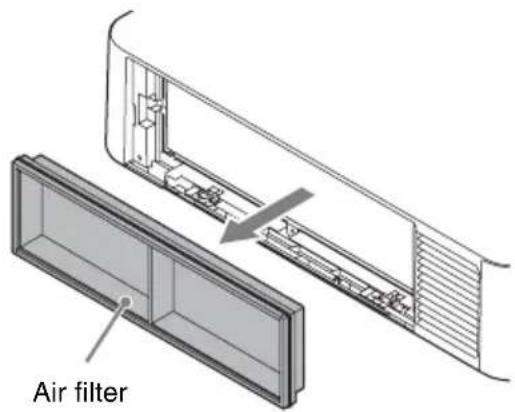
6 Clean the air filter with a vacuum cleaner.
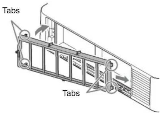
7 Replace the air filter and attach the filter cover.
When attaching the filter cover, fit the two tabs on the right into place, turn the filter cover using the right side as an axis, and fit the two tabs on the left into place. Then, tighten the four screws.
8 Fit the two tabs on the side cover into place and slide the side cover upward.
9 Lock the side cover.
Note
Be sure to attach the air filter firmly; the power cannot be turned on if it is not attached securely.
Replacing the Projection Lens
Notes
- Avoid removing/attaching the lens with the projector installed suspended from a ceiling.
- For usable projection lenses, see "Optional accessories" in the Operating Instructions.
- Do not attach any lens other than the specified accessory lens sold separately.
- Be careful not to drop the projection lens.
- Avoid touching the lens surface.
Removing
1 Return the projection lens to the center position.
While the unit is turned on, press the LENS SHIFT button on the Remote Commander, then press the RESET button on it. The projection lens returns to the center position.
Note
The projection lens cannot be removed unless it has returned to the center position.
2 Turn off the projector, then unplug the AC power cord from the wall outlet.
Caution
When replacing the lens, your eyes may be damaged if a strong light accidentally gets into your eyes. Before replacing the lens, turn off the projector and then unplug the AC power cord.
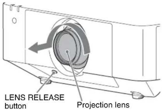
3 While pressing and holding down the LENS RELEASE button, rotate the projection lens counterclockwise to pull out the lens straight.
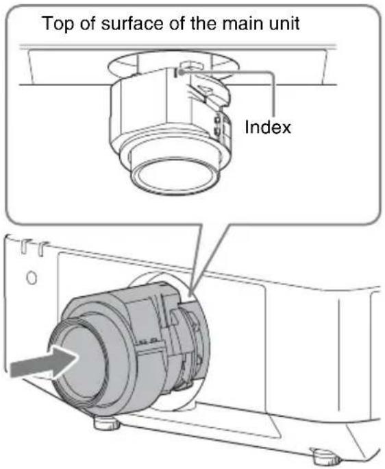
Attaching
1 Fully insert the projection lens with the index on the lens facing toward the top surface of the main unit.
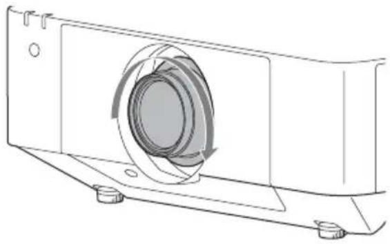
2 Rotate the lens clockwise until it clicks.
natural_image
Technical line drawing of a mechanical component with a circular housing and mounting base (no text or symbols)Note
When attaching the projection lens, do not press the LENS RELEASE button.
natural_image
Line drawing of a portable air conditioner unit emitting steam, with no text or symbols present.natural_image
Simple line drawing of a rectangular object with a circular opening and a prohibition symbol (no text or labels)natural_image
Simple line drawing of a firecracker with smoke and a prohibition symbol (no text or labels)natural_image
Simple 3D diagram of a rectangular block with a shaded side and a prohibition symbol above it (no text or labels)natural_image
Simple line drawing of a rectangular device with a coiled cable and a circular button, no text or symbols present.natural_image
Illustration of a steam rising from a chimney to a portable computer with smoke, no text or symbols presentnatural_image
Diagram showing airflow around a ventilation duct with a circular symbol (no text or labels)natural_image
Simple line drawing of a kitchen appliance with a bowl, chimney, and smoke (no text or symbols)natural_image
Illustration of a cigarette being dispensed from a device with smoke, no text or symbols presentnatural_image
Pure technical line drawing of a mechanical component without any text, numbers, or symbols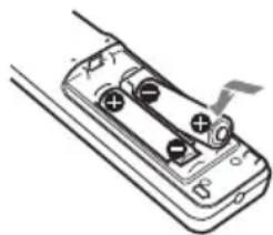
natural_image
Illustration of a handheld battery with two charging leads and a cable, no text or symbols present■ VPLL-Z3024, VPLL-Z3032
pie
| Category | Percentage (%) | |---|---| | Top Left | 60 | | Top Right | 32 | | Bottom Left | 5 | | Bottom Right | 32 |$$ \mathrm{VS} _ {+} = 6 0 - 1, 8 7 5 \times (\mathrm{HS} _ {+} \text {ou HS} -) [ \% ] $$
$$ \mathrm{VS} _ {-} = 5 - 0, 1 5 6 \times (\mathrm{HS} + \text { ou } \mathrm{HS} _ {-}) [ \% ] $$
$$ \mathrm{HS} _ {+} = \mathrm{HS} _ {-} = 32 - 0,533 \times \mathrm{VS} _ {+} [ \% ] $$
$$ \mathrm{HS} _ {+} = \mathrm{HS} _ {-} = 32 - 6,400 \times \mathrm{VS} _ {-} [ \% ] $$
■ VPLL-3007
$$ \mathrm{VS} _ {+} = 10 - 2,500 \times (\mathrm{HS} _ {+} \text {ou HS} _ {-}) [\% ] $$
$$ \mathrm{VS} _ {-} = 5 - 1,250 \times (\mathrm{HS} + \mathrm{ouHS} _ {-}) [\% ] $$
$$ \mathrm{HS} _ {+} = \mathrm{HS} _ {-} = 4 - 0, 4 0 0 \times \mathrm{VS} + [ \% ] $$
$$ \mathrm{HS} _ {+} = \mathrm{HS} _ {-} = 4 - 0, 8 0 0 \times \mathrm{VS} _ {-} [ \% ] $$
■ VPLL-Z3009

pie
| Category | Percentage (%) | |---|---| | Top Left | 50 | | Top Right | 24 | | Bottom Left | 5 | | Bottom Right | 24 |$$ \mathrm{VS} _ {+} = 50 - 2,083 \times (\mathrm{HS} _ {+} \text {ou HS} _ {-}) [\% ] $$
$$ \mathrm{VS} _ {-} = 5 - 0, 2 0 8 \times (\mathrm{HS} + \text { ou } \mathrm{HS} _ {-}) [ \% ] $$
$$ \mathrm{HS} _ {+} = \mathrm{HS} _ {-} = 24 - 0,480 \times \mathrm{VS} _ {+} [ \% ] $$
$$ \mathrm{HS} _ {+} = \mathrm{HS} _ {-} = 24 - 4,800 \times \mathrm{VS} _ {-} [ \% ] $$
■ VPLL-Z3010
pie
| Category | Percentage (%) | |---|---| | Top Left | 60 | | Top Right | 29 | | Bottom Left | 5 | | Bottom Right | 29 |$$ \mathrm{VS} _ {+} = 6 0 - 2, 0 6 9 \times (\mathrm{HS} _ {+} \text {ou HS} -) [ \% ] $$
$$ \mathrm{VS} - = 5 - 0, 1 7 2 \times (\mathrm{HS} + \text { ou } \mathrm{HS} -) [ \% ] $$
$$ \mathrm{HS} _ {+} = \mathrm{HS} _ {-} = 2 9 - 0, 4 8 3 \times \mathrm{VS} _ {+} [ \% ] $$
$$ \mathrm{HS} _ {+} = \mathrm{HS} _ {-} = 2 9 - 5, 8 0 0 \times \mathrm{VS} _ {-} [ \% ] $$
natural_image
Diagram of a mechanical component with an arrow indicating upward motion (no text or symbols)2 Fermez le cache-borne.
natural_image
Technical line drawing of an electronic device showing internal components and wiring (no text or symbols)Remarque
natural_image
Diagram of a projector with a button and internal components, showing no text or symbolsRemarques
natural_image
Technical diagram of a mechanical or electrical component with internal structure and ventilation slots (no text or symbols)natural_image
Technical line drawing of a mechanical component with a circular housing and mounting base (no text or symbols)Remarque
natural_image
Line drawing of a commercial kitchen with steam rising (no text or symbols)natural_image
Simple line drawing of a chimney on a roof with smoke and a prohibition symbol (no text or labels)natural_image
Simple 3D diagram of a rectangular block with a shaded side and a circular symbol above it (no text or labels)natural_image
Simple line drawing of a device with a plate and a prohibition symbol (no text or labels)natural_image
Illustration of a portable stove emitting steam, with a printer and computer monitor nearby (no text or symbols)natural_image
Diagram showing airflow around a ventilation grille and a 3D box with a valve (no text or symbols)natural_image
Simple line drawing of a kitchen appliance with a bowl, chimney, and smokestack emitting steam (no text or symbols)natural_image
Illustration of a hand using a cigarette to exhaust a cigarette from a device, with no visible text or symbols.natural_image
Technical line drawing of a mechanical component or bracket (no text or symbols)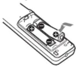
natural_image
Diagram of a battery pack with two cials and a switch, no text or symbols presentpie
| Category | Percentage (%) | |---|---| | Top Left | 70 | | Top Right | 32 | | Bottom Left | 5 | | Bottom Right | 32 |$$ \mathrm{VS} _ {+} = 70 - 2,187 \times (\mathrm{HS} + o \mathrm{HS} -) [\% ] $$
$$ \mathrm{VS} _ {-} = 5 - 0, 1 5 6 \times (\mathrm{HS} + \mathrm{oHS} _ {-}) [ \% ] $$
$$ \mathrm{HS} _ {+} = 32 - 0,457 \times \mathrm{VS} + [\% ] $$
$$ \mathrm{HS} - = 32 - 6,400 \times \mathrm{VS} - [\% ] $$
■ VPLL-Z3024, VPLL-Z3032
pie
| Category | Percentage (%) | |---|---| | Top Left | 60 | | Top Right | 32 | | Bottom Left | 5 | | Bottom Right | 32 |$$ \mathrm{VS} _ {+} = 6 0 - 1, 8 7 5 \times (\mathrm{HS} + \mathrm{oHS} -) [ \% ] $$
$$ \mathrm{VS} _ {-} = 5 - 0, 1 5 6 \times (\mathrm{HS} + \mathrm{oHS} _ {-}) [ \% ] $$
$$ \mathrm{HS} _ {+} = \mathrm{HS} _ {-} = 32 - 0,533 \times \mathrm{VS} _ {+} [ \% ] $$
$$ \mathrm{HS} _ {+} = \mathrm{HS} _ {-} = 32 - 6,400 \times \mathrm{VS} _ {-} [ \% ] $$
■ VPLL-3007

pie
| Category | Percentage (%) | |---|---| | Top Left | 10 | | Top Right | 4 | | Bottom Left | 5 | | Bottom Right | 4 |$$ \mathrm{VS} _ {+} = 10 - 2,500 \times (\mathrm{HS} + o \mathrm{HS} -) [\% ] $$
$$ \mathrm{VS} - = 5 - 1,250 \times (\mathrm{HS} + o \mathrm{HS} -) [\% ] $$
$$ \mathrm{HS} _ {+} = \mathrm{HS} _ {-} = 4 - 0, 4 0 0 \times \mathrm{VS} + [ \% ] $$
$$ \mathrm{HS} _ {+} = \mathrm{HS} _ {-} = 4 - 0, 8 0 0 \times \mathrm{VS} - [ \% ] $$
■ VPLL-Z3009

pie
| Segment | Percentage (%) | | :--- | :--- | | Top Left | 50 | | Top Right | 24 | | Bottom Left | 5 | | Bottom Right | 24 |$$ \mathrm{VS} _ {+} = 50 - 2,083 \times (\mathrm{HS} + o \mathrm{HS} -) [\% ] $$
$$ \mathrm{VS} - = 5 - 0,208 \times (\mathrm{HS} + o \mathrm{HS} -) [\% ] $$
$$ \mathrm{HS} _ {+} = \mathrm{HS} _ {-} = 24 - 0,480 \times \mathrm{VS} _ {+} [ \% ] $$
$$ \mathrm{HS} _ {+} = \mathrm{HS} _ {-} = 24 - 4,800 \times \mathrm{VS} _ {-} [ \% ] $$
■ VPLL-Z3010

pie
| Category | Percentage (%) | | :--- | :--- | | Top Left | 60 | | Top Right | 29 | | Bottom Left | 5 | | Bottom Right | 29 |$$ \mathrm{VS} _ {+} = 6 0 - 2, 0 6 9 \times (\mathrm{HS} + \mathrm{oHS} -) [ \% ] $$
$$ \mathrm{VS} _ {-} = 5 - 0, 1 7 2 \times (\mathrm{HS} + \mathrm{oHS} _ {-}) [ \% ] $$
$$ \mathrm{HS} _ {+} = \mathrm{HS} _ {-} = 29 - 0,483 \times \mathrm{VS} + [\% ] $$
$$ \mathrm{HS} _ {+} = \mathrm{HS} _ {-} = 2 9 - 5, 8 0 0 \times \mathrm{VS} - [ \% ] $$
natural_image
Diagram of a mechanical component with an arrow indicating direction (no text or symbols)natural_image
Technical line drawing of an electronic device showing internal components and wiring (no text or symbols)Nota
natural_image
Diagram of a projector with a screw and fan assembly, showing internal components (no text or symbols)Notas
natural_image
Technical diagram of a mechanical or electrical component with internal structure and ventilation slots (no text or symbols)natural_image
Technical diagram of a staircase with labeled component 'Asa' and directional arrows indicating motion (no text or symbols beyond label)natural_image
Technical line drawing of a mechanical component with a circular housing and mounting base (no text or symbols)Nota
natural_image
Pure electrical circuit lines without any symbolsnatural_image
Line drawing of a cluttered industrial machine with smokestacks emitting vapor (no text or symbols)natural_image
Simple line drawing of a rectangular object with a circular opening, next to a prohibition symbol (no text or labels)natural_image
Simple line drawing of a steaming block on a tray with a prohibition symbol above (no text or labels)natural_image
Simple 3D diagram of a rectangular block with a gray side and a prohibition symbol above it (no text or labels)natural_image
Simple line drawing of a rectangular device with a chain and a plate, no text or symbols present.natural_image
Illustration of a portable stove emitting steam, with a computer and a prohibition symbol (no text or labels)natural_image
Diagram of a ventilation system with exhaust pipe and fan (no text or symbols)natural_image
Simple line drawing of a kitchen appliance with a bowl, chimney, and smokestack emitting steam (no text or symbols)natural_image
Illustration of a cigarette being dispensed from a box with smoke, no text or symbols presentnatural_image
Pure technical line drawing of a mechanical component without any text, numbers, or symbols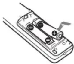
natural_image
Diagram of a battery pack with two batteries and a switch, no text or symbols presentpie
| Category | Percentage (%) | |---|---| | Top Left | 70 | | Top Right | 32 | | Bottom Left | 5 | | Bottom Right | 32 |$$ \mathrm{VS} _ {+} = 70 - 2,187 \times (\mathrm{HS} _ {+} \text {oder HS} _ {-}) [\% ] $$
$$ \mathrm{VS} _ {-} = 5 - 0, 1 5 6 \times (\mathrm{HS} + \text { oder } \mathrm{HS} -) [ \% ] $$
$$ \mathrm{HS} _ {+} = 32 - 0,457 \times \mathrm{VS} _ {+} [ \% ] $$
$$ \mathrm{HS} - = 32 - 6,400 \times \mathrm{VS} - [\% ] $$
■ VPLL-Z3024, VPLL-Z3032
pie
| Category | Percentage (%) | |---|---| | Top Left | 60 | | Top Right | 32 | | Bottom Left | 5 | | Bottom Right | 32 |$$ \mathrm{VS} _ {+} = 6 0 - 1, 8 7 5 \times (\mathrm{HS} + \text { oder } \mathrm{HS} -) [ \% ] $$
$$ \mathrm{VS} _ {-} = 5 - 0, 1 5 6 \times (\mathrm{HS} + \text { oder } \mathrm{HS} _ {-}) [ \% ] $$
$$ \mathrm{HS} _ {+} = \mathrm{HS} _ {-} = 32 - 0,533 \times \mathrm{VS} _ {+} [\% ] $$
$$ \mathrm{HS} _ {+} = \mathrm{HS} _ {-} = 32 - 6,400 \times \mathrm{VS} _ {-} [ \% ] $$
■ VPLL-3007
$$ \mathrm{VS} _ {+} = 1 0 - 2, 5 0 0 \times (\mathrm{HS} + \text { oder } \mathrm{HS} -) [ \% ] $$
$$ \mathrm{VS} _ {-} = 5 - 1,250 \times (\mathrm{HS} + \text { oder } \mathrm{HS} _ {-}) [\% ] $$
$$ \mathrm{HS} _ {+} = \mathrm{HS} _ {-} = 4 - 0, 4 0 0 \times \mathrm{VS} + [ \% ] $$
$$ \mathrm{HS} _ {+} = \mathrm{HS} _ {-} = 4 - 0, 8 0 0 \times \mathrm{VS} _ {-} [ \% ] $$
■ VPLL-Z3009
pie
| Category | Percentage (%) | |---|---| | Top Left | 50 | | Top Right | 24 | | Bottom Left | 5 | | Bottom Right | 24 |$$ \mathrm{VS} _ {+} = 50 - 2,083 \times (\mathrm{HS} _ {+} \text { oder } \mathrm{HS} _ {-}) [\% ] $$
$$ \mathrm{VS} - = 5 - 0, 2 0 8 \times (\mathrm{HS} + \text { oder } \mathrm{HS} -) [ \% ] $$
$$ \mathrm{HS} _ {+} = \mathrm{HS} _ {-} = 24 - 0,480 \times \mathrm{VS} _ {+} [ \% ] $$
$$ \mathrm{HS} _ {+} = \mathrm{HS} _ {-} = 24 - 4,800 \times \mathrm{VS} _ {-} [ \% ] $$
■ VPLL-Z3010
pie
| Category | Percentage (%) | |---|---| | Top Left | 60 | | Top Right | 29 | | Bottom Left | 5 | | Bottom Right | 29 |$$ \mathrm{VS} _ {+} = 6 0 - 2, 0 6 9 \times (\mathrm{HS} + \text { oder } \mathrm{HS} -) [ \% ] $$
$$ \mathrm{VS} - = 5 - 0, 1 7 2 \times (\mathrm{HS} + \text { oder } \mathrm{HS} -) [ \% ] $$
$$ \mathrm{HS} _ {+} = \mathrm{HS} _ {-} = 2 9 - 0, 4 8 3 \times \mathrm{VS} + [ \% ] $$
$$ \mathrm{HS} _ {+} = \mathrm{HS} _ {-} = 2 9 - 5, 8 0 0 \times \mathrm{VS} _ {-} [ \% ] $$
natural_image
Simple line drawing of a device with an arrow pointing to the button (no text or symbols)natural_image
Technical line drawing of an electronic device showing internal components and wiring (no text or symbols)Hinweis
natural_image
Diagram of a projector with internal components and a circular button, showing no text or symbols.Hinweise
natural_image
Technical diagram of a mechanical assembly with internal components and directional arrows (no text or symbols)natural_image
Technical line drawing of a mechanical component with a circular housing and mounting base (no text or symbols)Hinweis
natural_image
Pure electrical circuit lines without any symbolsParte anteriore del mobile
natural_image
Line drawing of a cluttered industrial machine with smoke and a no-smoking symbol above (no text or labels)natural_image
Simple line drawing of a rectangular object with a circular opening and a circular hole, alongside a circle with a prohibition symbol (no text or labels)natural_image
Simple line drawing of a smokestack on a platform with a prohibition symbol above (no text or labels)natural_image
Simple line drawing of a rectangular block with a shaded side and a prohibition symbol above (no text or labels)natural_image
Simple line drawing of a rectangular device with a coiled cable and a circular button, no text or symbols present.natural_image
Illustration of a portable stove emitting steam, with a printer and a monitor nearby (no text or symbols)natural_image
Diagram showing exhaust plume and exhaust hood with no text or symbolsnatural_image
Simple line drawing of a kitchen appliance with a bowl and smoke, no text or symbols presentnatural_image
Illustration of a cigarette being smoked or stayed in a box with smoke, no text or symbols presentnatural_image
Pure technical line drawing of a mechanical component with no text or symbols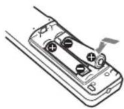
natural_image
Line drawing of a handheld electronic device with two circular buttons and a scroll wheel (no text or symbols)pie
| Category | Percentage (%) | |---|---| | Top Left | 70 | | Top Right | 32 | | Bottom Left | 5 | | Bottom Right | 32 |$$ \mathrm{VS} _ {+} = 70 - 2,187 \times (\mathrm{HS} + o \mathrm{HS} -) [\% ] $$
$$ \mathrm{VS} _ {-} = 5 - 0, 1 5 6 \times (\mathrm{HS} + \mathrm{oHS} _ {-}) [ \% ] $$
$$ \mathrm{HS} _ {+} = 32 - 0,457 \times \mathrm{VS} + [\% ] $$
$$ \mathrm{HS} - = 32 - 6,400 \times \mathrm{VS} - [\% ] $$
■ VPLL-Z3024, VPLL-Z3032

pie
| Category | Percentage (%) | |---|---| | Top Left | 60 | | Top Right | 32 | | Bottom Left | 5 | | Bottom Right | 32 |$$ \mathrm{VS} _ {+} = 6 0 - 1, 8 7 5 \times (\mathrm{HS} + \mathrm{oHS} -) [ \% ] $$
$$ \mathrm{VS} _ {-} = 5 - 0, 1 5 6 \times (\mathrm{HS} + \mathrm{oHS} _ {-}) [ \% ] $$
$$ \mathrm{HS} _ {+} = \mathrm{HS} _ {-} = 32 - 0,533 \times \mathrm{VS} _ {+} [ \% ] $$
$$ \mathrm{HS} _ {+} = \mathrm{HS} _ {-} = 32 - 6,400 \times \mathrm{VS} _ {-} [ \% ] $$
VPLL-3007
pie
| Category | Percentage (%) | |---|---| | Top Left | 10 | | Top Right | 4 | | Bottom Left | 5 | | Bottom Right | 4 |$$ \mathrm{VS} _ {+} = 10 - 2,500 \times (\mathrm{HS} + o \mathrm{HS} -) [\% ] $$
$$ \mathrm{VS} - = 5 - 1,250 \times (\mathrm{HS} + o \mathrm{HS} -) [\% ] $$
$$ \mathrm{HS} _ {+} = \mathrm{HS} _ {-} = 4 - 0, 4 0 0 \times \mathrm{VS} + [ \% ] $$
$$ \mathrm{HS} _ {+} = \mathrm{HS} _ {-} = 4 - 0, 8 0 0 \times \mathrm{VS} - [ \% ] $$
■ VPLL-Z3009
pie
| Segment | Percentage (%) | | :--- | :--- | | Top Left | 50 | | Top Right | 24 | | Bottom Left | 5 | | Bottom Right | 24 |$$ \mathrm{VS} _ {+} = 50 - 2,083 \times (\mathrm{HS} _ {+} \circ \mathrm{HS} _ {-}) [\% ] $$
$$ \mathrm{VS} - = 5 - 0,208 \times (\mathrm{HS} + o \mathrm{HS} -) [\% ] $$
$$ \mathrm{HS} _ {+} = \mathrm{HS} _ {-} = 24 - 0,480 \times \mathrm{VS} _ {+} [ \% ] $$
$$ \mathrm{HS} _ {+} = \mathrm{HS} _ {-} = 24 - 4,800 \times \mathrm{VS} _ {-} [ \% ] $$
■ VPLL-Z3010
pie
| Category | Percentage (%) | |---|---| | Top Left | 60 | | Top Right | 29 | | Bottom Left | 5 | | Bottom Right | 29 |$$ \mathrm{VS} _ {+} = 6 0 - 2, 0 6 9 \times (\mathrm{HS} + \mathrm{oHS} -) [ \% ] $$
$$ \mathrm{VS} - = 5 - 0, 1 7 2 \times (\mathrm{HS} + \mathrm{oHS} -) [ \% ] $$
$$ \mathrm{HS} _ {+} = \mathrm{HS} _ {-} = 29 - 0,483 \times \mathrm{VS} _ {+} [ \% ] $$
$$ \mathrm{HS} _ {+} = \mathrm{HS} _ {-} = 2 9 - 5, 8 0 0 \times \mathrm{VS} - [ \% ] $$
natural_image
Diagram of a mechanical component with an arrow indicating direction (no text or symbols)natural_image
Technical line drawing of an electronic device showing internal components and wiring (no text or symbols)Nota
natural_image
Diagram of a projector with a button and arrow indicating rotation (no text or symbols)Note
natural_image
Technical diagram of a mechanical or electrical component with internal structure and mounting bracket (no text or symbols)natural_image
Technical line drawing of a mechanical component with a circular housing and mounting base (no text or symbols)Nota
natural_image
Pure electrical circuit lines without any symbolsnatural_image
Line drawing of a portable air conditioner unit emitting steam (no text or symbols)natural_image
Simple line drawing of a rectangular object with a circular opening and a prohibition symbol (no text or labels)natural_image
Simple line drawing of a box on a tray with smoke and a prohibition symbol (no text or labels)natural_image
Simple line drawing of a rectangular block with a shaded side and a circular symbol above (no text or labels)natural_image
Simple line drawing of a rectangular device with a vertical rod and circular ports, no text or symbols present.natural_image
Illustration of a portable stove emitting smoke next to a portable printer and a CRT monitor, with a no-smoking symbol above (no text or labels)natural_image
Diagram showing a filtration or dust removal setup with a gridded tray and a 3D chamber, no text or symbols present.natural_image
Simple line drawing of a kitchen sink with a bowl and smoke, no text or symbols presentnatural_image
Illustration of a cigarette emitting smoke next to a box with a stop sign (no text or symbols on the diagram itself)natural_image
Pure technical line drawing of a mechanical component with no text or symbols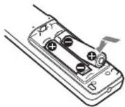
natural_image
Diagram of a battery pack with two terminals and a switch, no text or symbols present2Закройте крышку.
pie
| Category | Percentage (%) | |---|---| | Top Left | 70 | | Top Right | 32 | | Bottom Left | 5 | | Bottom Right | 32 |$$ \mathrm{VS} _ {+} = 7 0 - 2, 1 8 7 \times (\mathrm{HS} + \text { или} \mathrm{HS} -) [ \% ] $$
$$ V S _ {-} = 5 - 0, 1 5 6 \times (H S + и л и H S _ {-}) [ \% ] $$
$$ \mathrm{HS} _ {+} = 32 - 0,457 \times \mathrm{VS} + [\% ] $$
$$ \mathrm{HS} - = 32 - 6,400 \times \mathrm{VS} - [\% ] $$
■ VPLL-Z3024, VPLL-Z3032
pie
| Category | Percentage (%) | |---|---| | Top Left | 60 | | Top Right | 32 | | Bottom Left | 5 | | Bottom Right | 32 |$$ \mathrm{VS} _ {+} = 6 0 - 1, 8 7 5 \times (\mathrm{HS} + \text { или} \mathrm{HS} -) [ \% ] $$
$$ \mathrm{VS} _ {-} = 5 - 0, 1 5 6 \times (\mathrm{HS} + \text { или} \mathrm{HS} -) [ \% ] $$
$$ \mathrm{HS} _ {+} = \mathrm{HS} _ {-} = 32 - 0,533 \times \mathrm{VS} _ {+} [ \% ] $$
$$ \mathrm{HS} _ {+} = \mathrm{HS} _ {-} = 32 - 6,400 \times \mathrm{VS} _ {-} [ \% ] $$
■ VPLL-3007
boxplot
| Direction | Value (%) | |---|---| | Upward Arrow | 10 | | Downward Arrow | 4 | | Left Arrow | 4 | | Right Arrow | 5 | | Center Plus | + |$$ \mathrm{VS} _ {+} = 1 0 - 2, 5 0 0 \times (\mathrm{HS} + \text { или} \mathrm{HS} -) [ \% ] $$
$$ \mathrm{VS} _ {-} = 5 - 1, 2 5 0 \times (\mathrm{HS} + \text { или} \mathrm{HS} _ {-}) [ \% ] $$
$$ \mathrm{HS} _ {+} = \mathrm{HS} _ {-} = 4 - 0, 4 0 0 \times \mathrm{VS} + [ \% ] $$
$$ \mathrm{HS} _ {+} = \mathrm{HS} _ {-} = 4 - 0, 8 0 0 \times \mathrm{VS} _ {-} [ \% ] $$
■ VPLL-Z3009
pie
| Segment | Percentage (%) | | :--- | :--- | | Left | 50 | | Right | 24 | | Bottom | 5 | | Center Plus | + |$$ \mathrm{VS} _ {+} = 50 - 2,083 \times (\mathrm{HS} _ {+} \text { или} \mathrm{HS} _ {-}) [\% ] $$
$$ \mathrm{VS} _ {-} = 5 - 0, 2 0 8 \times (\mathrm{HS} + \text { или} \mathrm{HS} _ {-}) [ \% ] $$
$$ \mathrm{HS} _ {+} = \mathrm{HS} _ {-} = 24 - 0,480 \times \mathrm{VS} _ {+} [ \% ] $$
$$ \mathrm{HS} _ {+} = \mathrm{HS} _ {-} = 24 - 4,800 \times \mathrm{VS} _ {-} [ \% ] $$
■ VPLL-Z3010
boxplot
| Category | Value (%) | |---|---| | Top Left | 60 | | Top Right | 29 | | Bottom Left | 5 | | Bottom Right | 29 |$$ \mathrm{VS} _ {+} = 6 0 - 2, 0 6 9 \times (\mathrm{HS} + \text { или} \mathrm{HS} -) [ \% ] $$
$$ \mathrm{VS} - = 5 - 0, 1 7 2 \times (\mathrm{HS} + \text { или} \mathrm{HS} -) [ \% ] $$
$$ \mathrm{HS} _ {+} = \mathrm{HS} _ {-} = 29 - 0,483 \times \mathrm{VS} _ {+} [ \% ] $$
$$ \mathrm{HS} _ {+} = \mathrm{HS} _ {-} = 29 - 5,800 \times \mathrm{VS} _ {-} [ \% ] $$
natural_image
Pure mechanical component diagram without any text, numbers, or symbolsВыбор языка меню
natural_image
Technical line drawing of an electronic device showing internal components and wiring (no text or symbols)Примечание
natural_image
Diagram of a projector with a button and internal components, showing no text or symbolsПримечания
natural_image
Technical line drawing of a structural panel or enclosure with internal components and ventilation grilles (no text or symbols)natural_image
Technical line drawing of a mechanical component with a circular housing and mounting base (no text or symbols)Примечание
①INPUT A
Бейне: RGB/YP B PR кіріс терминалы (RGB/YP B PR) Аудио: аудио кіріс терминалы (AUDIO)
②INPUT B


- このマニュアルについて
- 熱感知器や煙感知器のそばに設置しない
- 警告
- ■ VPLL-Z3024、VPLL-Z3032
- VPLL-3007
- VPLL-Z3009
- VPLL-Z3010
- 電源コードを接続する
- メニューの表示言語を切り替える
- ご注意
- Step 1
- Step 2
- Step 3
- English
- WARNING
- CAUTION
- IMPORTANT
- For the customers in the U.S.A.
- Supplier's Declaration of Conformity
- For the customers in Canada
- For the customers in Europe, Australia and New Zealand
- For the customers in Europe
- For the customers in other countries/regions
- Light source specifications
- The distance L' between the front of the lens (center) and the front of the cabinet
- For the Customers in Brazil only
- For the customers in Taiwan only
- 第一類雷射產品
- For dealers
- Safety precautions for installing the unit on a ceiling
- On Installation
- On cleaning the lens and the cabinet
- On Illumination
- On Heat Dissipation
- On Screen
- On Fan
- About Lens Replacement
- On inspection of light source related parts
- On disposing used products
- On LCD Projector
- On condensation
- Notes on security
- Notes
- Checking the Supplied Accessories
- Using the CD-ROM manual
- Note
- Installing batteries
- Projection Distance and Lens Shift Range
- Projection distance
- Projection distance formula
- Lens shift range
- Connecting the AC Power Cord
- Selecting the Menu Language
- Connecting a Computer
- Attaching the terminal cover
- Opening the terminal cover
- Projecting an Image
- Adjusting the Focus, Size, and Position of the Projected Image
- Adjusting the tilt of the projector with the front feet (adjustable)
- Displaying a pattern for adjusting an image
- Automatically Optimizing Projector Settings
- Select usage location of the projector from the following options.
- Select "Apply," then press the ENTER key.
- Turning Off the Power
- Indicators
- Operating status indication
- Cleaning the Air Filter
- Replacing the Projection Lens
- Removing
- Attaching
- Remarque
- Remarques
- Nota
- Notas
- Hinweis
- Hinweise
- Выбор языка меню
- Примечание
- Примечания
Brand : SONY
Model : VPLFHZ75
Category : Projector