S 5004 - Pan TRUMA - Free user manual and instructions
Find the device manual for free S 5004 TRUMA in PDF.
| Product type | Gas heater for leisure vehicles |
| Brand | Truma |
| Model | S 5004 |
| Nominal heating power | 6000 W |
| Gas consumption | 60 to 480 g/h |
| Gas type | Liquefied gas (propane/butane) |
| Operating pressure | 30 mbar |
| Power supply | 1.5 V battery (type LR6, AA) for automatic igniter |
| Weight | Approx. 17.5 kg (without fan) |
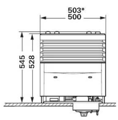
| Dimensions (approx.) | See diagram figure 10 (height ~590 mm, width ~410 mm, depth ~210 mm) |
| Ignition | Automatic spark ignition (battery) |
| Ventilation | Compatible with TEB-3 fan (optional, integrated control for two fans) |
| Lighting | Optional, activation by proximity sensor (20 s) |
| Thermostat | Manual adjustment (positions 1-5 and off) |
| Maintenance | Annual cleaning of heat exchanger, bottom plate and fan wheel |
| Battery replacement | Before each heating season, use a waterproof battery resistant to +70°C |
| Safety | Automatic shut-off, ignition safety, safety gas shut-off in case of interruption (according to UN-ECE 122 regulation) |
| Warranty | 24 months (according to manufacturer's conditions) |
| Repairability | Repairs only by authorized Truma specialist personnel |
| Approval | For caravans, motorhomes and mobile homes (class O, M1) according to EN 1949 |
| Main accessories | Removable front panel, exhaust hose, chimney, extensions SKV/AKV |
Frequently Asked Questions - S 5004 TRUMA
User questions about S 5004 TRUMA
0 question about this device. Answer the ones you know or ask your own.
Ask a new question about this device
Download the instructions for your Pan in PDF format for free! Find your manual S 5004 - TRUMA and take your electronic device back in hand. On this page are published all the documents necessary for the use of your device. S 5004 by TRUMA.
USER MANUAL S 5004 TRUMA
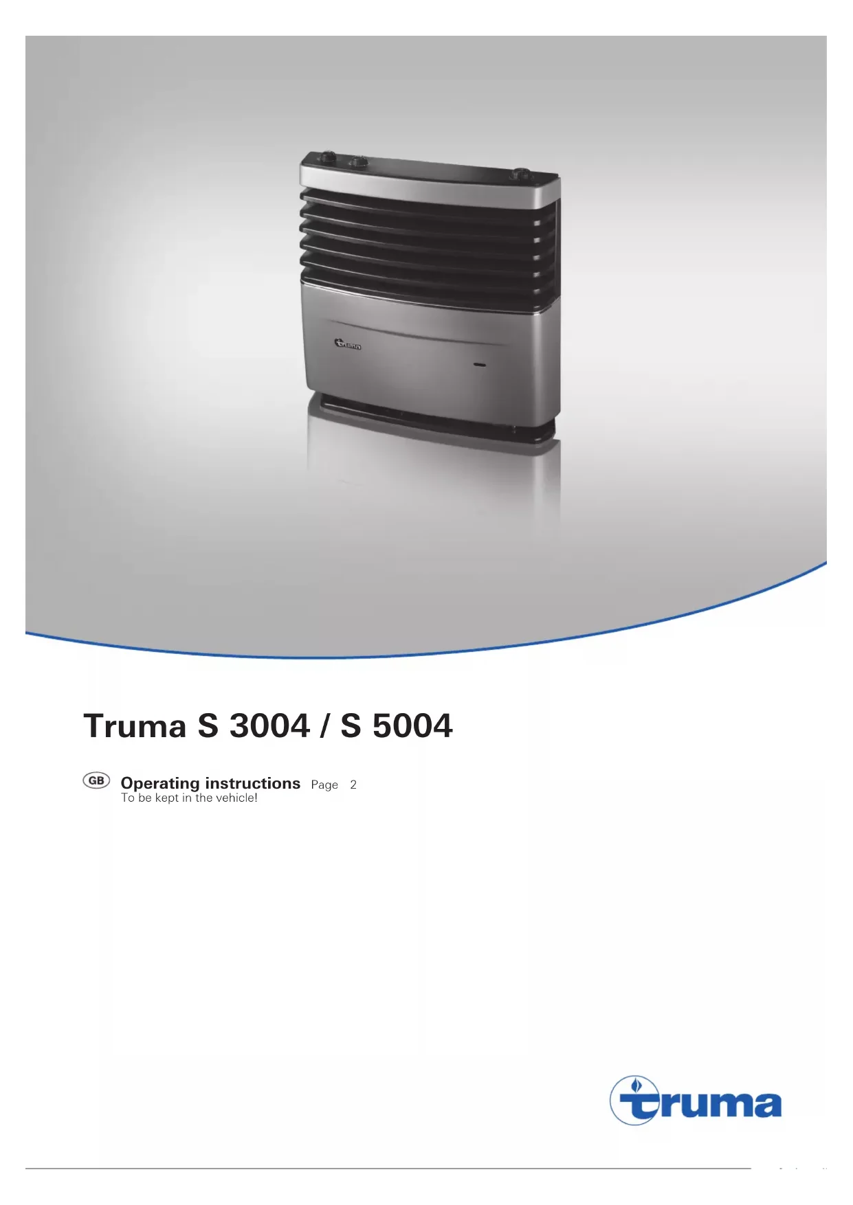
Operating instructions
Page
2
To be kept in the vehicle!
Table of contents
Symbols used 2
Intended use 2
Truma S 3004 2
Truma S 5004 2
Safety instructions 3
Operating instructions
Design 6
Truma S 3004 6
Truma S 5004 6
Start-up 6
Burner ignition 6
Operation of the fan 6
Lighting 7
Room thermostat 7
Switching off 7
Maintenance 7
Cleaning the heater 7
Removing the cover 7
Fitting the cover 7
Auto ignitor battery change 8
Special information 8
Disposal 8
Technical data 8
Dimensions 9
Manufacturer's Warranty
(European Union) 10
Read the safety instructions and operating instructions carefully before starting the appliance.
Intended use
Truma S 3004
Proper use
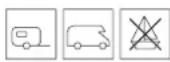
The appliance is approved solely for installation and operation in caravans and construction trailers of vehicle class O, motor homes of vehicle class M1 and mobile homes if the gas system is installed in accordance with EN 1949. The national legislation and regulations for operating and testing gas installations (e.g. DVGW Work Sheet G 607 in Germany) must be observed.
The appliance may be used only to heat the vehicle's interior.
If the appliance is operated while the vehicle is in motion, facilities must be installed to prevent uncontrolled emission of liquefied gas in the event of an accident (according to UN-ECE regulation 122).
If the appliance is being used for commercial purposes, the operator must ensure that special statutory and insurance regulations of the respective destination country are observed.
Improper use
All other uses not listed under proper use are improper and therefore prohibited. This applies for example to installation and operation in:
Motor buses of vehicle classes M2 and M3
Commercial vehicles of vehicle class N,
Boats and other water vessels.
Hunting / forestry huts, weekend homes or awnings.
Installation in trailers and vehicles used to transport hazardous goods is prohibited
Defective appliances must not be used.
Appliances installed and utilised in contravention of the operating and installation instructions must not be used.
Truma S 5004
Proper use
The appliance is approved solely for installation and operation in caravans and construction trailers of vehicle class O and mobile homes if the gas system is installed in accordance with EN 1949. The national legislation and regulations for operating and testing gas installations (e.g. DVGW Work Sheet G 607 in Germany) must be observed.
The appliance may be used only to heat the vehicle's interior.
If the appliance is operated while the vehicle is in motion, facilities must be installed to prevent uncontrolled emission of liquefied gas in the event of an accident (according to UN-ECE regulation 122).
If the appliance is being used for commercial purposes, the operator must ensure that special statutory and insurance regulations of the respective destination country are observed.
Improper use
All other uses not listed under proper use are improper and therefore prohibited. This applies for example to installation and operation in:
"Motor homes" of vehicle class M1,
Motor buses of vehicle classes M2 and M3.
Commercial vehicles of vehicle class N,
-Boats and other water vessels.
Hunting / forestry huts, weekend homes or awnings.
Symbols used

Symbol indicates possible hazards.

Risk of burns! Hot surface.

Wear protective gloves to prevent possible mechanical injuries.

Observe the ESD regulations!

Note containing information and tips.
Installation in trailers and vehicles used to transport hazardous goods is prohibited
Defective appliances must not be used.
Appliances installed and utilised in contravention of the operating and installation instructions must not be used.
Safety instructions

Only competent and trained persons (experts) may install and repair the
Truma product and carry out the function test in accordance with the installation and operating instructions and the currently accepted technical regulations. Experts are persons who, based on their specialist instruction and training, their knowledge and experience with Truma products and the relevant standards, can carry out the necessary work properly and identify potential hazards.

To ensure safe and proper use, carefully read and observe the operating instruc
tions and other documents supplied with the product, and keep them in a safe place for future reference. The respective valid laws, directives and standards must be observed.
Not following the rules in the operating and installation instructions can result in serious material damage and serious risk to the health or life of persons. The appliance's operator or user is solely responsible for such damage.

The use of upright gas cylinders from which gas is taken in the gas phase is
mandatory for the operation of gas regulators, gas equipment and gas systems. Gas cylinders from which gas is taken in the liquid phase (e.g. for fork lifts) must not be used, since they would result in damage to the gas system.

What must I do if I smell gas?
-
Avoid ignition sources, e.g. extinguish all naked flames, do not actuate any electrical switches or use any mobile phones or radios in the vehicle, do not start the vehicle's engine, do not operate any appliances, do not smoke.
-
Open windows and doors.
Evacuate all persons from the vehicle. - Shut off gas cylinders and/or shut off the gas supply from the outside.
- Have the entire gas system inspected and repaired by experts.
- Do not put the gas system back into operation until after it has been inspected and repaired.
Danger of toxic exhaust fumes! The heater's exhaust can be toxic in enclosed or poorly ventilated spaces (e.g. garages, workshops).
If the vehicle is parked in such rooms:
- Shut off the fuel supply to the heater.
- Switch the heater off on the control panel.
An open roof window / lifting roof in the vicinity of the exhaust cowl may allow exhaust gas to enter the interior of the vehicle. The heater may only be operated when the roof window / lifting roof is closed.
Danger of fire / explosion during refuelling! The appliance must not be operated during refuelling:
the vehicle,
- the caravan's towing vehicle or
- other appliances.
Switch off the LP gas appliance at the control panel. Shut off the gas supply to the LP gas appliance. Make sure that the LP gas appliance can definitely not be switched on under any circumstances.

Possible injury / material damage if the heater is operated without a cover. Due
to hot surfaces on the heat exchanger, operate the heater only with the cover fitted.

Danger of explosion due to improper repairs or modifications to the gas system.
Only experts may carry out this work.

Repairs to the heater may only be carried out by an expert! Work on burner nozzles
may only be done by experts.

A new O-ring must be fitted whenever the exhaust gas system has been removed!

The 30 mbar operating pressure of the gas supply must correspond with the operating pressure of the appliance (see type 1).

The appliance, the gas system and the exhaust duct for the combustion product must be inspected by a recognised expert. Cordance with the national regulations (DVGW Worksheet G 607 in Germany) or, if there are no such regulations, at least every 5 years.
-
A recognised specialist must carry out a leak test after changes have been made to the liquid gas system.
-
The vehicle owner is responsible for having the check carried out.
During the initial start-up of a brand new appliance, small quantities of fumes and a slight odour may briefly occur. When the appliance is started up after a particularly long period of non-use, there may be some smoke and/or smell due to dust or dirt. It is a good idea to allow the appliance to run at maximum output for a few minutes for the purpose of self-cleaning and to ensure that the area is well ventilated.
An unusual burning noise or flame increase is indicative of a regulator defect and means that the regulator must be checked.
Objects (e.g. spray cans) or flammable materials / liquids must not be stored in the same compartment where the appliance is installed or in the appliance itself, because under certain conditions elevated temperatures may arise there.
In Germany, only pressure regulating equipment that complies with DIN EN 16129 (in vehicles) with a fixed output pressure of 30 mbar may be used for the gas system. The flow rate of the pressure regulating equipment must at least match the maximum consumption of all the equipment that is installed.
We recommend the MonoControl CS gas pressure regulation system for vehicles, and also the DuoControl CS gas pressure regulation system for the two-cylinder gas system.
At temperatures of around 0^ and below, the gas pressure regulation system or the changeover valve should be operated with the EisEx regulator heater.
Controller connecting hoses that meet national regulations must always be used in the respective destination country. These hoses must be checked regularly for brittleness.
Pressure regulating devices and hoses must be replaced with new ones no more than 10 years after their date of manufacture (every 8 years if used commercially). The operator is responsible for this.
Possible fire hazard! There must not be any combustible materials (e.g hay, leaves, fabrics) in the vicinity of the combustion air intake.
The combustion air intake under the vehicle floor and the cowl for the exhaust gas system must be kept free of obstructions (slush, ice, leaves etc.) at all times.
The exhaust cowl must be kept free in the air flow during operation of the heater. Roof structures may interfere with the function of the heater.
Snow must be cleared from the cowl before the heater is started up during the winter. For winter camping and long-term camping, we recommend the SKV cowl extension that can be screwed to the cowl part (3× 15cm)
If the heater keeps going out in extremely windy locations or during the winter, we recommend the use of an AKV cowl extension (15 cm) and also the T-2 or T-3 cowl top.
If two or three 15cm extensions are used, they must be removed before the vehicle is in motion so that they are not lost (risk of accident). Remaining extensions must be screwed in place.
If a canopy is fitted to the caravan, it is essential to lead the exhaust cowl through this roof. Use the cowl lead-through UEK for this.
The heat exchanger, the exhaust duct and all connections must be checked by an expert at regular intervals, and always after loud combustion (misfiring).
The exhaust duct must:
- be firmly attached to the heater and the cowl without leaks,
- consist of one piece (without joints),
- be routed without cross-section narrowing and rising over its entire length,
- be firmly attached with several clamps together with the insulating duct (duct UR).
No objects must be placed onto the exhaust duct, since this could lead to damage.
Heaters with wrongly fitted or damaged exhaust ducts or damaged heat ex-changers must not continue to be used!
Due to the danger of overheating and fire, the heater's warm air outlet must not be obstructed under any circumstances. Therefore, no textiles or similar are to be hung in front of or onto the heater for drying. Incorrect use can damage your heater and the fabrics caused by overheating. Do not bring any combustible objects in the vicinity of the heater!
The heater cover becomes hot by design during operation. This can be a danger particularly to children and persons with reduced physical, sensory or mental capabilities, and can cause burn injuries. The operator has a duty of care and supervision towards third parties. The operator must point out possible hazards (e.g. risk of burn injuries, fire hazard) to third parties. In particular, children under 8 years old must be supervised at all times while the appliance is in operation, and must be kept away from it.
This appliance may be used by children aged 16 or over and by persons with reduced physical, sensory or mental capabilities or with a lack of experience only if they are supervised and have been instructed in the safe use of the appliance and understand the resulting risks.
Children must not be allowed to play with the appliance.
The stickers enclosed with the appliance must be affixed by the installer or vehicle owner in a location in the vehicle and close to the heater that is clearly visible to all users! Missing stickers can be requested from Truma.
Heating while driving
For heating while driving, the UN ECE regulation 122 stipulates a safety shut-off device to prevent the uncontrolled escape of gas in the event of an accident. The MonoControl CS gas pressure regulation system fulfils this requirement.
National regulations and rules must be followed.
If no safety shut-off device (e.g. MonoControl CS) is installed, the gas cylinder must be closed while driving and notices must be attached in accordance with the valid regulations.
Design
Truma S 3004
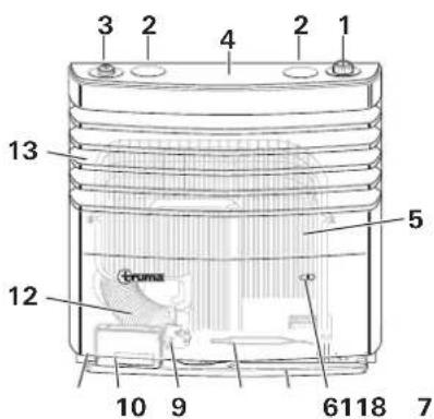
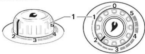
Figure 1
1 = Control knob (thermostat)
2 = Blind cover
3 = Integrated control panel for a fan TEB-3
4 = Sensor surface for switching the lighting on (optional)
5 = Heat exchanger
6 = Mica window for observing the flame
7 = Base plate
8 = Thermostat sensor
9 = Exhaust gas connection (exhaust connection, pressure plate, O-ring)
10 = Auto ignitor with battery compartment
11=Typeplate
12 = Exhaust duct
13 = Warm air outlet / cover
The diagram shows right-handed installation. With left-handed installation, some parts are located on the other side (mirror inverted).
Truma S 5004
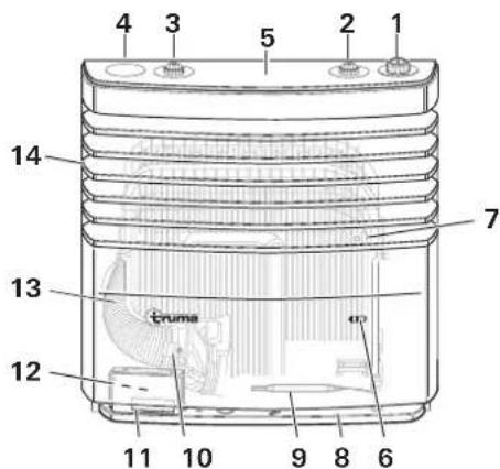
Figure 2
1 = Control knob (thermostat)
2 = Integrated control panel for a TEB-3 Truma fan
3 = Integrated control panel for a second TEB-3 Truma fan
4 = Blind cover
5 = Sensor surface for switching the lighting on (optional)
6 = Mica window for observing the flame
7 = Heat exchanger
8 = Base plate
9 = Thermostat sensor
10 = Exhaust gas connection (exhaust connection, pressure plate, O-ring)
11 = Auto ignitor with battery compartment
12 = Type plate
13 = Exhaust duct
14 = Warm air outlet / cover
Start-up
Burner ignition
Before operation, ensure that there is a new battery with sufficient charge in the auto ignitor.
Possible risk of misfiring! Reduced ignition frequency due to an old or weak battery in the auto ignitor.
- At least two ignition sparks must be visible per second.
-
If this is not the case, replace the battery in the auto ignitor (see "Auto ignitor battery change").
-
Open the gas cylinder and quick-acting valve in the gas supply line.
- Turn the control knob (Figure 3-1) to the thermostat position 1 - 5 and push in as far as it will go (maximum 30 seconds). Ignition with an audible ignition spark takes place automatically in this period.
- Monitor the ignition process through the mica window (Figure 1-6 or 2-6). A flame can be seen when ignition is successful.
- After a successful ignition, keep the control knob held down for another 10 seconds so that the safety pilot responds.
Possible risk of misfiring!
- Wait for at least three minutes before trying again if there is a fault or if ignition was unsuccessful.
- Contact service following three unsuccessful ignition attempts.
If the flame goes out during operation, immediate automatic re-ignition takes place within the closing time of the safety pilot (approx. 30 seconds). In the event that ignition is unsuccessful despite repeated attempts (e.g. because the gas cylinder is empty), the auto ignitor continues to operate until the control knob (Figure 3 - 1) is set to "0".
In order to achieve even and quick warm air distribution and to lower the surface temperatures at the warm air outlet grille, we recommend operating the heater with the Truma warm air system running.
Operation of the fan
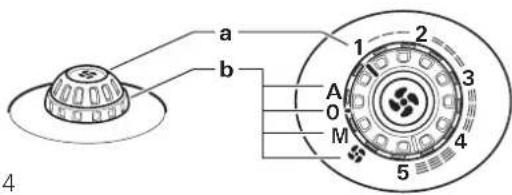
Figure 4
a = Control knob / dial for fan power (1 - 5)
b = Rotary switch / dial for operating modes
A Automatic -The electronics control the required fan power and limit the speed to the value set at the control knob.
0 OFF -Switch off fan.
M Manual -Adjusting the fan power.
Booster level - Set fan speed to the highest value (for maximum air volume flow).
Lighting
The lighting (optional) for the control panels is activated by a proximity switch. To do this, touch the middle of the cover from above. This switches on the lighting for approx. 20 seconds.
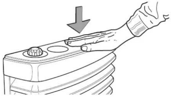
Figure 5
The sensor electronics of the lighting calibrate themselves whenever the 12V supply voltage is applied. This can take several seconds. Do not touch the cover during calibration.
Room thermostat
An average room temperature of approx. 22^ can be achieved with a thermostat setting of approx. 3 without fan operation. We recommend operation with the fan and a thermostat setting of approx. 4 for comfortable warm air distribution and to reduce the amount of condensation on cold surfaces.
The exact thermostat setting must be determined in accordance with the design of the vehicle and the individual heating requirement.
The thermostat sensor is located at the bottom of the heater. Please note that cold draughts caused by refrigerator ventilation, door cracks etc. or deep pile carpets adversely affect the thermostat. Sources of interference such as this must be remedied, otherwise there is no guarantee of satisfactory temperature control.
Switching off
Set the control knob of the heater to position "0" (the auto ignitor is switched off at the same time).
Switch off fan (move rotary switch to "0").
If the appliance is not used for a long period, close the gas cylinder and the quick-acting valve in the gas supply line.
Maintenance

Possible burn injury hazard if contact is made with the hot heater. Clean only when the heater is switched off as cooled down.

In spite of careful manufacturing, the heater may contain sharp parts. Therefore, please always use protective ties during maintenance and cleaning work!

Electrostatic charging can destroy the electronics. Ensure that potential compensation is present before ing the electronics.
Cleaning the heater
-
Accumulated dust on the heat exchanger, base plate and fan wheel of the Truma warm air system must be removed at least once annually. Carefully clean the fan wheel with a paintbrush or small brush.
-
After an extended period of non-use, inspect the heat exchanger for dirt and clean it if necessary

It is prohibited to use products containing chlorine on and inside the appliance.
Removing the cover

Possible burn injury hazard if contact is made with the hot heater. Do not remove the cover unless the heater tched off and has cooled down.
The cover is unlocked by pushing the two locking levers (1) outwards simultaneously. It can be swivelled out and lifted from the lower bearings.
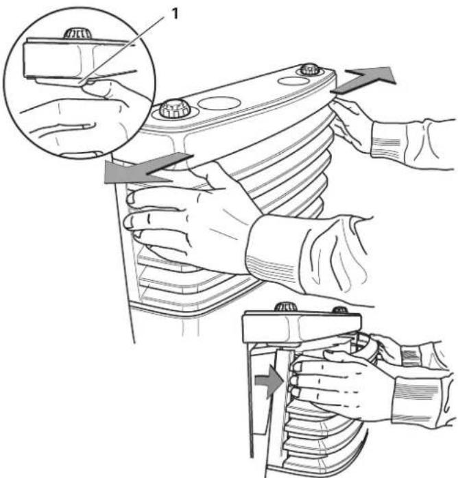
Figure 6
Fitting the cover
Hook cover into the lower bearings (1) and swivel in (2) until catch audibly engages. Pull cover to make sure that it is securely attached.
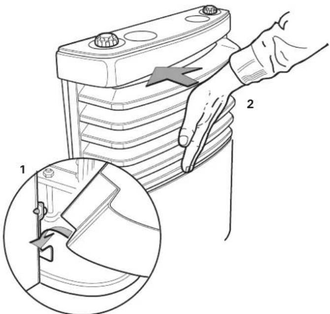
Figure 7
Auto ignitor battery change
-
If no ignition spark is heard during start-up or if fewer than two ignition sparks are visible per second, the battery must be replaced.
-
Insert a new battery at beginning of every heating season.

Always use temperature-resistant (+70^) , leakproof 1.5V Mignon batteries (LR 6, AA, AM 3) (part no. 30030-99200), or batteries could cause malfunctions.

Possible burn injury hazard if contact is made with the hot heater. Always ensure that heater is switched off as cooled down before replacing batteries.
- Remove the cover.
- Slide the battery compartment cover upwards and replace the battery. Pay attention to positive / negative.
- Close battery compartment again.
- Re-attach the cover.
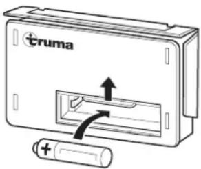
Figure 8
Battery disposal

The battery may not be disposed of with domestic refuse, instead it must be sent for recycling via a collection point. By doing this you are contributing towards reuse and ing.
Special information
If the vehicle floor is coated with underfloor protection, all heater parts located beneath the vehicle must be covered so that the resulting spray mist does not cause heater system malfunctions. Remove covers again when the work is complete.
Disposal
Dispose of the appliance and battery in the auto ignitor separately in accordance with the administrative regulations of the relevant country of use. National regulations and laws (in Germany, for example, the End-of-Life Vehicle Regulation) must be observed.
In other countries, the relevant regulations must be observed.
Technical data
(determined in accordance with EN 624 or Truma test conditions)
S 3004 / S 5004
Gas type
Liquefied gas (propane / butane)
Operating pressure
30 mbar (see type plate)
Rated heat output
S 3004:3500 W
S 5004:6000W
Gas consumption
S 3004: 30 - 280 g/h
S 5004: 60 - 480 g/h
Additional information in accordance with EN 624
S 3004: Q_n = 4.0 kW (Hs) ; 290 g/h; C6
S 5004: Q_n = 6.8kW (Hs); 490 g/h; C51
Appliance
category
Destination countries
3B/P(30)
AT, BE, BG, CH, CY, CZ, DE, DK, EE, ES, FI
FR,GB,GR,HR,HU,IE,IS,IT,LI,LT,LU
LV, MT, NL, NO, PL, PT, RO, SE, SI, SK, TR
13+28-30/37]
BE, CH, CZ, ES, FR, GB, GR, IE, IT, PT, SI
Operating voltage
1.5 V (auto ignitor with battery operation)
Power consumption
225 mW (ignition)
Weight
S 3004: approx. 10.3kg (without fan)
S 5004: approx. 17.5kg (without fan)

0085
S 3004:
S 5004:

Subject to technical changes.
Dimensions
S 3004
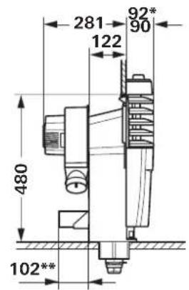
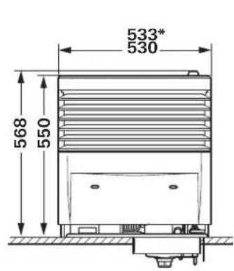
Figure 9
S 5004
Figure 10
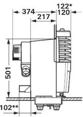
With decorative chrome strip
* Truma Ultraheat (optional)
Measurements in mm with tolerance of +2mm / -1mm Subject to technical changes.
Manufacturer's Warranty (European Union)
1. Scope of Manufacturer's Warranty
As the Manufacturer of the appliance, Truma undertakes a warranty towards the Consumer that covers any material and/or manufacturing defects of the appliance.
This Warranty is applicable in EU member states as well as in Iceland, Norway, Switzerland and Turkey. A Consumer is the natural person who was the first one to purchase the appliance from the Manufacturer, OEM or dealer and who neither resold the appliance in a commercial or self-employed professional capacity nor installed it for a third party in such a capacity.
The Manufacturer's Warranty covers any of the aforementioned defects that occur within 24 months upon concluding the purchase agreement between the seller and the Consumer. The Manufacturer or an authorised service partner undertakes to remedy such defects through subsequent fulfilment, i.e. at its discretion either by repairing or replacing the defective item. Any defective parts shall become the property of the Manufacturer or the authorised service partner. If the appliance is no longer manufactured at the time of defect notification and if replacement delivery has been opted for, then the Manufacturer may deliver a similar product.
If the Manufacturer remedies a defect under its warranty commitment, the term of the Warranty shall not start again with regard to the repaired or replaced parts; rather, the original warranty period shall continue to be applicable to the appliance. Only the Manufacturer itself and an authorised service partner shall be entitled to conduct a warranty job. Any costs that occur in the event of a warranty claim shall be settled directly between the authorised service partner and the Manufacturer. The Warranty does not cover additional costs arising from complicated removal or installation jobs on the appliance (e.g. dismantling of furnishings or parts of the vehicle body), and neither does it cover travel expenses incurred by the authorised service partner or the Manufacturer.
No further-reaching claims shall be permitted, especially damage claims presented by the Consumer or third parties. This provision shall not affect the validity of the German Product Liability Act (Produkttaftungsgesetz).
The voluntary manufacturer's warranty does not affect the consumer's legally valid claims for defects against the seller in the relevant country of purchase. In individual countries there may be warranties that can be issued by the relevant dealer (official distributor, Truma Partner). In such cases the warranty can be implemented directly through the dealer from whom the Consumer bought the appliance. The warranty regulations of the country in which the appliance was purchased by the Consumer for the first time shall also be applicable.
2. Warranty exclusions
No warranty claim shall be applicable under the following circumstances:
- Improper, unsuitable, faulty or negligent use and any use that is not compliant with the intended purpose
- Improper installation, assembly or commissioning, contrary to operating or installation instructions
- Improper operation or operation contrary to operating or installation instructions, particularly any disregard for maintenance, care or warning notes,
- Instances where installations, repairs or any other procedures have been conducted by non-authorised parties
- Consumable materials and parts which are subject to natural wear and tear
- Installation of replacement, supplementary or accessory parts that are not original manufacturer's parts or which have not been approved by the manufacturer. This applies in particular if the appliance is subject to networked control, if the control units or the software have not been approved by Truma or if the Truma control unit (e.g. Truma CP plus or Truma iNet Box) has not been exclusively used for controlling Truma appliances or appliances approved by Truma.
- As a consequence of damage arising from foreign substances (e.g. oil, or plasticisers in the gas), chemical or electrochemical influences in the water, or cases when the appliance has come into contact with unsuitable substances (e.g. chemical products, flammable substances or unsuitable cleaning agents)
- Damage caused by abnormal environmental or unsuitable operating conditions
- Damage caused by force majeure or natural disasters or any other influences not within Truma's responsibility
- Damage resulting from improper transport
- End customer's or third-party modifications of the appliance, including any replacement, supplementary or accessory parts, or installation of the same, especially concerning the exhaust gas system or the cowl.
3. Making a warranty claim
The warranty must be claimed with an authorised service partner or at the Truma Service Centre. All the relevant addresses and phone numbers can be found at www.truma.com, in the "Service" section.
The Manufacturer's address is:
85640 Putzbrunn, Germany
To ensure a smooth procedure, we would be grateful if you could have the following details ready before contacting us:
Detailed description of the defect
- Serial number of the appliance
-Date of purchase
The authorised service partner or the Truma Service Centre will then specify the further procedure. To avoid transport damage, the affected appliance must only be shipped by prior arrangement with the authorised service partner or the Truma Service Centre.
If the warranty claim is recognised by the Manufacturer, then the transport expenses shall be borne by the same. If no warranty claim is applicable, the Consumer will be notified accordingly and any repair and transport expenses shall then be the Consumer's liability. We ask you not to send in an appliance without prior arrangement.
GB Should problems occur, please contact the Truma Service Centre or one of our authorised service partners (see www.truma.com).
In order to avoid delays, please have the unit model and serial number ready (see type plate).
Truma S 3004 / S 5004

Mode d'emploi
Page 2
S3004:Q=4,0kW(Hs);290g/h;C
S5004:Qn" = 6,8 kW (Hs); 490 g/h; C51
Categorié
d'appareil
Pays de destination
130/P130
AT, BE, BG, CH, CY, CZ, DE, DK, EE, ES, FI
FR, GB, GR, HR, HU, IE, IS, IT, LI, LT, LU
LV, MT, NL, NO, PL, PT, RO, SE, SI, SK, TR
13+28-30/37]
BE, CH, CZ, ES, FR, GB, GR, IE, IT, PT, SI
LV, MT, NL, NO, PL, PT, RO, SE, SI, SK, TR
BE,CH,CZ,ES,FR,GB,GR,IE,IT,PT,SI
LV, MT, NL, NO, PL, PT, RO, SE, SI, SK, TR
BE,CH,CZ,ES,FR,GB,GR,IE,IT,PT,SI
Bedrijffsspanning
1,5 V (op batterij werkende ontstekingsautomaat)
Stroomopname
225 mW (ontsteken)
Gewicht
S 3004: ca. 10,3kg (zonder ventilator)
S 5004: ca. 17,5 kg (zonder ventilator)

0085
S 3004:

S 5004: