Exagon 400 CCCV - Welding machine GYS - Free user manual and instructions
Find the device manual for free Exagon 400 CCCV GYS in PDF.

User questions about Exagon 400 CCCV GYS
0 question about this device. Answer the ones you know or ask your own.
Ask a new question about this device
Download the instructions for your Welding machine in PDF format for free! Find your manual Exagon 400 CCCV - GYS and take your electronic device back in hand. On this page are published all the documents necessary for the use of your device. Exagon 400 CCCV by GYS.
USER MANUAL Exagon 400 CCCV GYS
natural_image
Line drawing of a mechanical testing device with control panel and ventilation slots (no text or symbols)FR 2 / 3-13 / 92-100
EN 2 / 14-24 / 92-100
DE 2 / 25-36 / 92-100
ES 2 / 36-46 / 92-100
RU 2 / 47-58 / 92-100
NL 2 / 59-69 / 92-100
IT 2 / 70-80 / 92-100
PL 2 / 81-91 / 92-100
EXAGON 400 CC/CV
FIG-1
text_image
Technical diagram of an industrial machine with numbered components and labeled parts
text_image
Technical diagram of a mechanical device with labeled parts 7 and 8, showing internal components and flow direction.FIG-2
text_image
1 2 34 VRD V 8.8.8 0 +9 -9 ARC FORCE INDUCTANCE 7 8 910 12 1311 14 6 5 18 Basic 7018 RVIL 6013 Cellulosic 6010 15 16 17 20 21 22 23 MODE Gouging press 3 s MMA MIGTIG Basic 7018 RVIL 6013 Cellulosic 6010 MODE setup memory press 3press 3sAVERTISSEMENTS - RÈGLES DE SÉCURITÉ
CONSIGNE GÉNÉRALE

text_image
Diagram illustrating human and furniture positioning with a 30-degree angle indicatorINSTALLATION – FONCTIONNEMENT PRODUIT
INTERFACE HOMME MACHINE (IHM) (FIG-2)
text_image
VRD V 160 A 9 9 MMA MIG TIG Gouging Fruit MILK Failure MUSY Clock MUSY MODE IKES: setup memorytext_image
MMA MIG TIG Gouging MODEMESSAGES D'ERREUR, ANOMALIES, CAUSES, REMÈDES
Read and understand the following safety recommendations before using or servicing the unit. Any change or servicing that is not specified in the instruction manual must not be undertaken.
The manufacturer is not liable for any injury or damage due to a non-compliance with the instructions featured this manual.
In the event of problems or uncertainties, please consult a qualified person to handle the installation properly.
ENVIRONMENT
This equipment must only be used for welding operations in accordance with the limits indicated on the descriptive panel and/or in the user manual. The operator must respect the safety precautions that apply to this type of welding. In case of inedaquate or unsafe use, the manufacturer cannot be held liable for damage or injury.
This equipment must be used and stored in a place protected from dust, acid or any other corrosive agent. Operate the machine in an open, or well-ventilated area.
Operating temperature:
Use between -10 and +40°C (+14 and +104°F).
Store between -20 and +55°C (-4 and 131°F).
Air humidity:
Lower or equal to 50% at 40°C (104°F).
Lower or equal to 90% at 20°C (68°F).
Altitude:
Up to 1000 meters above sea level (3280 feet).
INDIVIDUAL PROTECTIONS AND OTHERS
Arc welding can be dangerous and can cause serious and even fatal injuries.
Welding exposes the user to dangerous heat, arc rays, electromagnetic fields, noise, gas fumes, and electrical shocks. People wearing pacemakers are advised to consult with their doctor before using this device.
To protect oneself as well as the other, ensure the following safety precautions are taken:

In order to protect you from burns and radiations, wear clothing without cuffs. These clothes must be insulated, dry, fireproof and in good condition, and cover the whole body.

Wear protective gloves which guarantee electrical and thermal insulation.

Use sufficient welding protective gear for the whole body: hood, gloves, jacket, trousers... (varies depending on the application/operation). Protect the eyes during cleaning operations. Do not operate whilst wearing contact lenses.
It may be necessary to install fireproof welding curtains to protect the area against arc rays, weld spatters and sparks.
Inform the people around the working area to never look at the arc nor the molten metal, and to wear protective clothes.

Ensure ear protection is worn by the operator if the work exceeds the authorised noise limit (the same applies to any person in the welding area).
Stay away from moving parts (e.g. engine, fan...) with hands, hair, clothes etc...
Never remove the safety covers from the cooling unit when the machine is plugged in - The manufacturer is not responsible for any accident or injury that happens as a result of not following these safety precautions.
The pieces that have just been welded are hot and may cause burns when manipulated. During maintenance work on the torch or the electrode holder, you should make sure it's cold enough and wait at least 10 minutes before any intervention. The cooling unit must be on when using a water cooled torch in order to ensure that the liquid does not cause any burns.
ALWAYS ensure the working area is left as safe and secure as possible to prevent damage or accidents.
WELDING FUMES AND GAS

The fumes, gases and dust produced during welding are hazardous. It is mandatory to ensure adequate ventilation and/or extraction to keep fumes and gases away from the work area. An air fed helmet is recommended in cases of insufficient air supply in the workplace.
Check that the air intake is in compliance with safety standards.
Care must be taken when welding in small areas, and the operator will need supervision from a safe distance. Welding certain pieces of metal containing lead, cadmium, zinc, mercury or beryllium can be extremely toxic. The user will also need to degrease the workpiece before welding.
Gas cylinders must be stored in an open or ventilated area. The cylinders must be in a vertical position secured to a support or trolley.
Do not weld in areas where grease or paint are stored.
FIRE AND EXPLOSIONS RISKS

Protect the entire welding area. Compressed gas containers and other inflammable material must be moved to a minimum safe distance of 11 meters.
A fire extinguisher must be readily available.
Be careful of spatter and sparks, even through cracks.
It can be the source of a fire or an explosion.
Keep people, flammable objects and containers under pressure at a safe distance.
Welding of sealed containers or closed pipes should not be undertaken, and if opened, the operator must remove any inflammable or explosive materials (oil, petrol, gas...).
Grinding operations should not be directed towards the device itself, the power supply or any flammable materials.
GAS BOTTLE

Gas leaking from the cylinder can create a hazard if present in high concentrations around the work area.
Transport must be done safely: Cylinders closed and product off. Always keep cylinders in an upright position securely chained to a fixed support or trolley.
Close the bottle after any welding operation. Be careful with gas bottles placed in areas of high temperature, or in sunlight.
Cylinders should be located away from areas where they may be struck or subjected to physical damage.
Always keep gas bottles at a safe distance from arc welding or cutting operations, and any source of heat, sparks or flame.
Be careful when opening the valve on the gas bottle, it is necessary to remove the tip of the valve and make sure the gas meets your welding requirements.
ELECTRIC SAFETY

The machine must be connected to an earthed electrical supply. Use the recommended fuse size.
An electrical discharge can directly or indirectly cause serious accidents, if not deadly.
Do not touch any live part of the machine (inside or outside) when it is plugged in (Torches, earth cable, cables, electrodes) because they are connected to the welding circuit.
Before opening the device, it is imperative to disconnect it from the mains and wait 2 minutes, so that all the capacitors are discharged.
Do not touch the torch or electrode holder and earth clamp at the same time.
Damaged cables and torches must be changed by a qualified and skilled professional.
Make sure that the cable cross section is adequate with the usage (extensions and welding cables).
Always wear dry clothes in good condition, in order to be insulated from the electrical circuit. Wear insulating shoes, regardless of the environment in which you work in.
EMC CLASSIFICATION

These Class A devices are not intended to be used on a residential site where the electric current is supplied by the public network, with a low voltage power supply. There may be potential difficulties in ensuring electromagnetic compatibility on these sites, because of the interferences, as well as radio frequencies.

This equipment does not comply with IEC 61000-3-12 and is intended to be connected to private low-voltage systems interfacing with the public supply only at the medium- or high-voltage level. On a public low-voltage power grid, it is the responsibility of the installer or user of the device to ensure, by checking with the operator of the distribution network, which device can be connected.
This equipment complies with the IEC 61000-3-11 standard.
ELECTROMAGNETIC INTERFERENCES

The electric currents flowing through a conductor cause electrical and magnetic fields (EMF). All welders should use the following guidelines to minimize exposure to electromagnetic fields from the welding circuit.
- Regroup the electrode cables and earth clamp. If possible, attach them with tape
- Do not roll the electrode cable, torch or the earth clamp around the body.
- Do not stand between the cables. If the electrode cable or torch is on the right, the work cable should also be on the right.
- Connect the earth cable to the workpiece, as close as possible to the welding area.
- Do not work next to the welding power source.

People wearing pacemakers are advised to consult their doctor before using this device.
Exposure to electromagnetic fields while welding may have other health effects which are not yet known.
RECOMMENDATIONS TO ASSES THE AREA AND WELDING INSTALLATION
Overview
The user is responsible for installing and using the arc welding equipment in accordance with the manufacturer's instructions. If electromagnetic disturbances are detected, it is the responsibility of the user of the arc welding equipment to resolve the situation with the manufacturer's technical assistance. In some cases, this remedial action may be as simple as earthing the welding circuit. In other cases, it may be necessary to construct an electromagnetic shield around the welding power source and around the entire piece by fitting input filters. In all cases, electromagnetic interferences must be reduced until they are no longer bothersome.
Welding area assessment
Before installing the machine, the user must evaluate the possible electromagnetic problems that may arise in the area where the installation is planned.
. In particular, it should consider the following:
a) the presence of other power cables (power supply cables, telephone cables, command cable, etc...) above, below and on the sides of the arc welding machine.
b) television transmitters and receivers;
c) computers and other hardware;
d) critical safety equipment such as industrial machine protections;
e) the health and safety of the people in the area such as people with pacemakers or hearing aids;
f) calibration and measuring equipment
g) The isolation of the equipment from other machinery.
The user will have to make sure that the devices and equipments that are in the same room are compatible with each other. This may require extra precautions;
h) make sure of the exact hour when the welding and/or other operations will take place.
The surface of the area to be considered around the device depends on the building's structure and other activities that take place there. The area taken in consideration can be larger than the limits determined by the companies.
Welding area assessment
Besides the welding area, the assessment of the arc welding systems installation itself can be used to identify and resolve cases of disturbances. The assessment of emissions must include in situ measurements as specified in Article 10 of CISPR 11. In situ measurements can also be used to confirm the effectiveness of mitigation measures.
RECOMMENDATION ON METHODS OF ELECTROMAGNETIC EMISSIONS REDUCTION
a. National power grid: The arc welding machine must be connected to the national power grid in accordance with the manufacturer's recommendation. If interferences occur, it may be necessary to take additional preventive measures such as the filtering of the power supply network. Consideration should be given to shielding the power supply cable in a metal conduit. It is necessary to ensure the shielding's electrical continuity along the cable's entire length. The shielding should be connected to the welding current's source to ensure good electrical contact between the conduct and the casing of the welding current source.
b. Maintenance of the arc welding equipment: The arc welding machine should be submitted to a routine maintenance check according to the manufacturer's recommendations. All accesses, service doors and covers should be closed and properly locked when the arc welding equipment is on.. The arc welding equipment must not be modified in any way, except for the changes and settings outlined in the manufacturer's instructions. The spark gap of the arc start and arc stabilization devices must be adjusted and maintained according to the manufacturer's recommendations.
c. Welding cables: Cables must be as short as possible, close to each other and close to the ground, if not on the groud.
d. Electrical bonding: consideration should be given to bonding all metal objects in the surrounding area. However, metal objects connected to the workpiece increase the risk of electric shock if the operator touches both these metal elements and the electrode. It is necessary to insulate the operator from such metal objects.
e. Earthing of the welded part: When the part is not earthed because for electrical safety reasons or because of its size and its location (which is the case with ship hulls or metallic building structures), the earthing of the part can, in some cases but not systematically, reduce emissions. It is preferable to avoid the earthing of parts that could increase the risk of injury to the users or damage other electrical equipments. If necessary, it is appropriate that the earthing of the part is done directly, but in some countries that do not allow such a direct connection, it is appropriate that the connection is made with a capacitor selected according to national regulations.
f. Protection and plating: The selective protection and plating of other cables and devices in the area can reduce perturbation issues. The protection of the entire welding area can be considered for specific situations.
TRANSPORT AND TRANSIT OF THE MACHINE

The machine is equipped with two handles to facilitate transport, which requires two people. Be careful not to underestimate the machine's weight.
Do not use the cables or torch to move the machine. The welding equipment must be moved in an upright position.
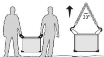
text_image
Diagram illustrating human and chair positions with a 30-degree angle indicator, showing hand positioning and seat arrangement.Never lift the machine while there is a gas cylinder on the support shelf. Transportation standards are different. Do not place/carry the unit over people or objects.
INSTALLATION
Rules to follow:
- Put the machine on the floor (maximum incline of 10^ .)
- Ensure the work area has sufficient ventilation for welding, and that there is easy access to the control panel.
- The machine must be placed in a sheltered area away from rain or direct sunlight.
- The machine must not be used in an area with metal dusts.
- The machine protection level is IP23, which means :
- Protection against access to dangerous parts from solid bodies of a ≥12.5mm diameter and,
- Protection against the rain inclined at 60° towards the vertical.
These devices can be used outside in accordance with the IP23 protection index. - The power cables, extensions and welding cables must be fully uncoiled to prevent overheating.

The manufacturer does not incur any responsibility regarding damages to both objects and persons that result from an incorrect and/or dangerous use of the machine.
MAINTENANCE / RECOMMENDATIONS


- Maintenance should only be carried out by a qualified person.
-
Ensure the machine is switched off by unplugging it, and then wait 2 minutes before carrying out maintenance work. High Voltage and Currents inside the machine.
-
Remove the casing 2 or 3 times a year to remove any excess dust. Take this opportunity to have the electrical connections checked by a qualified person, with an insulated tool.
- Regularly check the condition of the power supply cable. If the power cable is damaged, it must be replaced by the manufacturer, its after sales service or an equally qualified person to prevent danger.
- Ensure the ventilation holes of the device are not blocked to allow adequate air circulation.
- Do not use this equipment to thaw pipes, to charge batteries, or to start any engine.
INSTALLATION – PRODUCT OPERATION
Only qualified personnel authorized by the manufacturer should perform the installation of the welding equipment. During set up, the operator must ensure that the machine is unplugged. It is recommended to use the welding cables supplied with the unit in order to obtain the optimum product settings.
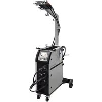
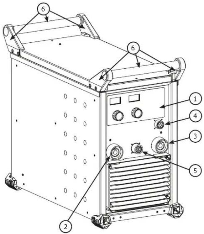
HARDWARE DESCRIPTION (FIG-1)
The Exagon 400 CC-CV is a three phase inverter welder which, depending on its equipment, can do :
- Electrode welding (MMA)
- Semi automatic welding (MIG/MAG/flux cored wire)
- Tungsten electrode welding (TIG)
- Carbon electrode gouging
The TIG process requires gas shielding (Argon).
The MMA process can weld any type of electrode : rutile, basic, cellulosic, stainless and brass.
The 400 CC-CV can be equipped with a remote control or foot pedal.
1- Man to Machine Interface 5- Wire feeder control cable connector
2- + polarity plug 6- Transport handles and lifting rings
3- - polarity plug 7- On/off switch
4- Remote control cable connector 8- Power supply cable (5 m)
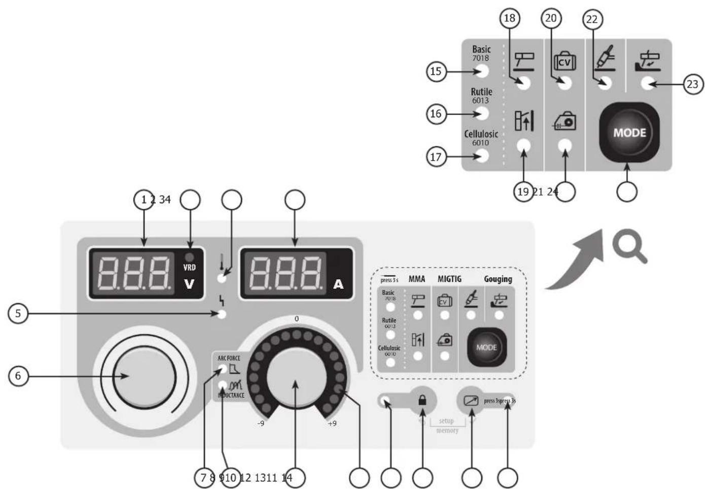
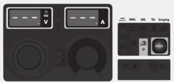
CONTROL BOARD (MMI) (FIG-2)
1- Voltage display 13- Remote control activation button
2- Active risk reduction system indicator (VRD) 14- Active remote control indicator
3- Current display 15- Basic electrode indicator
4- Overheat indicator 16- Rutile electrode indicator
5- Disruption of normal operations indicator
6- Main setting knob. 18- MMA mode indicator
7- Arc-force setting indicator
8- Variable inductance setting indicator
9- Indicators
10- Secondary setting knob
11- Locked keypad indicator
12- Locked keypad button
17- Cellulosic electrode indicator
19- MMA pulse mode indicator
20- Voltage mode indicator (CV)
21- Semi-automatic mode indicator
22- TIG mode indicator
23- Gouging mode indicator
24- Selection mode button
POWER SUPPLY – STARTING UP
- The welders are fitted with a 32 A socket type EN 60309-1 which must be connected to a three-phase 400V (50 - 60 Hz) power supply fitted with four wires and one earthed neutral.
The absorbed effective current (I1eff) is displayed on the machine, for optimal use. Check that the power supply and its protection (fuse and/or circuit breaker) are compatible with the current needed by the machine. In some countries, it may be necessary to change the plug to allow the use at maximum settings.
- The machine ie designed to work on a 400V +/- 15% power supply.
- The device turns into protection mode if the power supply tension below 340V RMS or over 460V RMS. To signal this fault, the screen displays an error code.
- The start is done via an on / off switch (7) set to I, and the stop is done by switching it to O. Attention! Never disconnect the power supply when the machine is on.
CONNECTION ON A GENERATOR
The machine can work with generators as long as the auxiliary power matches these requirements :
- The voltage must be AC, always superior to 400Vac ±15%, and the peak voltage below 700V,
- The frequency must be between 50 and 60 Hz.
It is imperative to check these requirements as several generators generate high voltage peaks that can damage these machines.
USE WITH EXTENSION CABLES
All extension cables must have an adequate size and section, relative to the machine's voltage. Use an extension that complies with national safety regulations.
Current input Extension selection (<45m)
400V 2.5 mm²
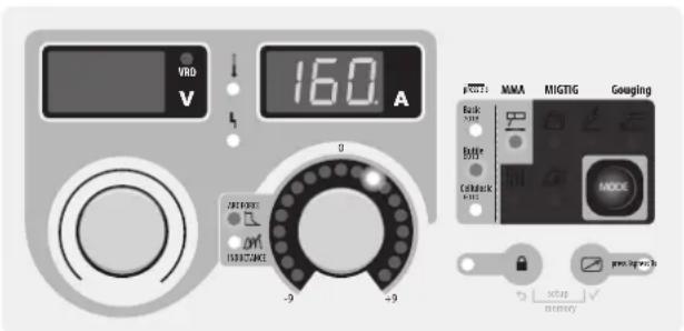
ELECTRODE WELDING (MMA AND MMA VERTICAL UP)
CONNECTIONS AND RECOMMENDATIONS
- Connect the cables, electrode holder and earth clamp in the connectors,
- Respect the welding polarities and intensities indicated on the electrodes boxes,
- Remove the electrode from the electrode holder when the machine is not in use.
text_image
VBD V 160 A MMA MIGTIG Gouaging Back Power Batter Suits Cathodeck Puls MODE -9 -9 OUT POWER OUT INFLUENCE setup memoryMMA
The grey areas are not useful for this mode.
text_image
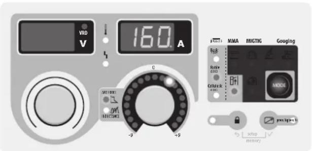
VRD V 160 A MMA MIGTIG Gouging OFF Ruler 2313 Cellurck +8 -9 +9 RESET MISTOME setup memoryMMA Vertical up
The grey areas are not useful for this mode.
MODE SELECTION
Press the button several times until the LED light switches on below the symbol or The MMA vertical up mode adds a current pulse which makes vertical up welding easier.

MAIN SETTINGS
1. Selection of the electrode's coating type :
Selection of the electrode's coating type by maintaining the MODE button for more than 3 seconds until the LED switches on below the corresponding symbol.
2. Welding intensity settings :
Adjust the welding current using the main knob (○) according to the electrode diameter and the type of assembly to be carried out. The current setpoint is indicated on the right side display.
Adjust the arcforce level with the right side knob, a relative value from -9 to +9. The lower the arcforce, the softer the arc. The higher the arcforce, the higher the extra welding current. The default value is 0.
WELDING PARAMETERS
WELDING INTENSITY SETTINGS
The following settings concern the intensity range that may be used depending on the electrode's type and diameter. These ranges are quite large as they depend on the application and the welding position.
| ∅ electrode (mm) | Rutile E6013 (A) | Basic E7018 (A) | Cellulosic E6010 (A) |
| 1.6 30-60 30-55 - | |||
| 2.0 50-70 50-80 - | |||
| 2.5 60-100 80-110 60-75 | |||
| 3.15 80-150 90-140 85-90 | |||
| 4.0 100-200 125-210 120-160 | |||
| 5 150-290 200-260 110-170 | |||
| 6.3 200-385 220-340 - | |||
ARCFORCE SETTINGS
It is recommended to set the arc force in median position (0) to start the welding and adjust it according to the results and welding preferences. Note: the arcforce setting range is specific to the selected electrode type.
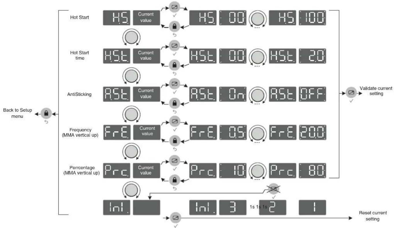
ADVANCED SETTINGS
Refer to the chapter « menu access » for more details regarding welding parameters.
The two MMA modes and come with the following additional settings :
HS : HotStart, level of the extra current at arc strike, expressed in percentage of the welding current.
HSE: Hotstart Time, duration of the extra current at arc strike, expressed in seconds.
R5. : Antisticking, active (On), the current will stop after 2 consecutive seconds of short circuit, inactive (Off), the current will not stop, even in the event of long short circuit.
In MMA vertical up mode two extra settings are available :
FrE: Frequency, determines the number of pulses per second (Hz).
Prc: Percentage, determines the background/cold current expressed in percentage of the welding current.
TUNGSTEN ELECTRODE WELDING WITH INERT GAS (TIG
CONNECTIONS AND RECOMMENDATIONS
TIG welding requires a torch as well as a gas bottle equipped with a regulator.
Connect the earth clamp to the positive connector (+).
Connect the torch's earth cable to the negative plug (-).
Connect the torch's gas hose to the regulator's output.
Ensure that the torch is equipped and ready to weld, and that the consumables (Vise grip, ceramic gas nozzle, collet and collet body) are not damaged.
MODE SELECTION
Press the button MODE several times until the LED light switches on below the symbol 🔊.
WELDING STETTINGS
1. Welding intensity settings :
Adjust the welding current using the main knob according to the diameter and the type of assembly to be carried out. The current setpoint is indicated on the right side display.
2. Welding downslope settings :
Adjust the downslope duration using the secondary knob. The indicator shows the chosen settings, the right display indicates the precise downslope duration in seconds.
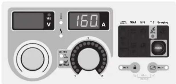
text_image
VND V 160 A 2 9 -9 +9 MMA MIG TIG Gouging MOCK pvs.1k mimmingThe grey areas are not useful for this mode.
ARC STRIKE / IGNITION :
LIFT start : Using the torch, make contact between the electrode and the metal piece, then slightly lift the electrode to start the arc.
WELD STOP / SWITCHING TO DOWNSLOPE :
To stop the weld, slightly lift the torch, the intensity will gradually reduce (downslope).
ASSISTANCE FOR SETTING UP AND SELECTING CONSUMABLES
| DC |  | Current (A) Electrode (mm) Shroud (mm) | Argon flow rate (L/min) | |
| 0.3 - 3 mm 5 - 75 | 1 6.5 6 - 7 | |||
| 2.4 - 6 mm 60 - 150 | 1.6 8 6 - 7 | |||
| 4 - 8 mm 100 - 200 | 2 9.5 7 - 8 | |||
| 6.8 - 8.8 mm 170 - 220 | 2.4 11 8 - 9 | |||
| 9 - 12 mm | 255 - 300 3.2 | 12.5 9 - 10 |
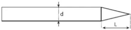
ELECTRODE GRINDING
text_image
d LL = 3 x d for a low current.
L = 3 x d for a high current
SEMI-AUTOMATIC MIG / MAG WELDING WITH WIRE FEEDER (EXAFEED 📄)
CONNECTIONS AND RECOMMENDATIONS
- Connect the earth clamp on the positive (+) or negative (-) terminal depending on the wire type (in general on the -),
- Connect the connection cable on the remaining power connector,
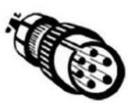
- Plug the connection cable's command connector on the 10 points base situated between the two power connectors (FIG-1, n°5),
- Refer to the wire feeder's user manual for the remaining connections.
MODE SELECTION AND SETTINGS
Press the button MODE several times until the LED light switches on below the symbol 🔒.
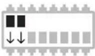
Both display show - - - and the knobs are inactive, all controls are now operated from the wire feeder's interface (Refer to the wire feeder's user manual for the control settings).
text_image
VVD V A PNO 1s MMA MIG TIG Gouging MCKThe grey areas are not useful for this mode.
SEMI-AUTOMATIC MIG / MAG WELDING WITH VOLTAGE DETECTING WIRE FEEDER (CV)
CONNECTIONS AND RECOMMENDATIONS
- Connect the earth clamp on the positive (+) or negative (-) terminal depending on the wire type (in general on the -),
- Connect the wire feeder on the connector using a male-female cable (NOMAD CABLE),
- Refer to the wire feeder's user manual for the remaining connections.
MODE SELECTION AND SETTINGS
Press the button MODE several times until the LED light switches on below the symbol [cv].
1. Setting the welding voltage :
Adjust the welding voltage using the main knob (○) depending on the work to be carried out. The voltage setpoint is indicated on the left side display.
2. Inductance settings :
Adjust the inductance level using the second knob (1), a relative value from -9 to +9. The lower the inductance level, the harder and more guiding the arc. The higher the inductance and the softer the arc with little splatter.
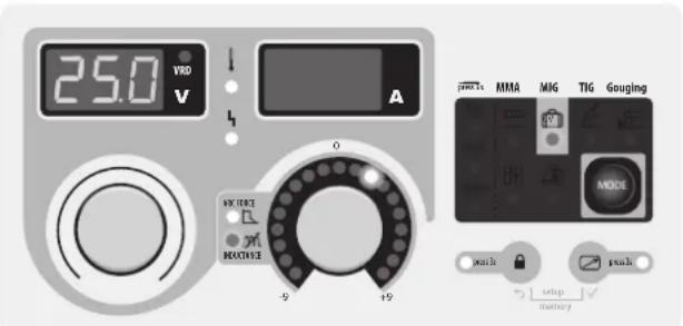
text_image
25.0 VRD V A 0 -9 +9 MMA MIG TIG Gouging MODE push setup memory pushThe grey areas are not useful for this mode.
CARBON ARC GOUGING
CONNECTIONS AND RECOMMENDATIONS
- Connect the earth clamp on the negative (-) terminal
- Connect the gouging torch on the positive (+) terminal
- Orient the clamp depending on the working position, make sure that the compressed air flows in the arc's direction and not the other way around.
- Place a carbon electrode,
- Connect the compressed air to the gouging torch,
The arc strike is easier : just make contact with the piece, and advance while pushing the electrodes towards the metal to be removed.
MODE SELECTION AND SETTINGS
Press the button MOL several times until the LED light switches on below the symbol
Adjust the arc voltage using the main knob (○), the voltage setpoint is indicated on the left side display.
• 36V to 45V for a 6.35 mm electrode.
• 39V to 45V for a 8 mm electrode.
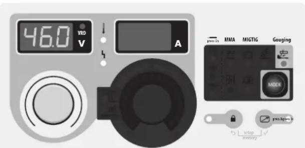
text_image
46.0 VRED V A pnu1is MMA MIGTIG Gouging MODE pnu1pina B setup inventoryThe grey areas are not useful for this mode.
DISPLAY CURRENT/VOLTAGE DURING WELDING
During welding, the machine measures and displays the welding current and voltage. After the weld, the average current and voltage values are displayed during 30 seconds, as soon as a knob or a button is pressed, the welding parameters are displayed.
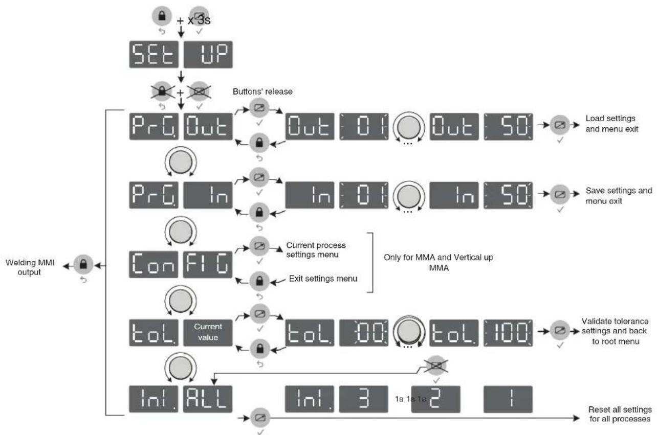
SAVE AND LOAD WELDING SETTINGS
The current settings are automatically saved and loaded at start up.
On top of the current settings, it is also possible to save and load 50 settings per each mode.
The memory recalls :
- Primary setting
- Secondary setting (MMA, CV)
- Secondary settings (MMA)
Save new settings :
- Maintain buttons and during 3 seconds. appears, release the buttons.
- Turn one of the two knobs - Validate by pressing the button .
- The display indicates a memory set (01 to 50) while blinking.
- Turn the knob to select the memory set in which the desired settings will be saved. Validate by pressing the button
- The settings are saved / the menu exit is instantaneous.
Load existing settings :
- Maintain the buttons and during 3 seconds. appears, release the buttons.
- Turn one of the two knobs to display . Validate by pressing the button .
- The display indicates a memory set (01 to 50) while blinking.
- Turn one of the two knobs to select the memory set containing the desired settings to load. Validate by pressing the button The settings are loaded / the menu exit is instantaneous.


REMOTE CONTROL

The remote control option or pedal option has not been designed to operate on the EXAGON when the EXATIG (ref. 013780) is connected. The current can be adjusted by using the potentiometer torch (ref. 047877) connected to the EXATIG which controls the EXAGON's current level.
CONNECTIONS AND RECOMMENDATIONS
The remote control works in all modes (except in semi-auto mode with a workshop wire feeder where all controls are on the wire feeder).
The remote control acts on the primary settings of the current process (MMA and TIG, voltage and gouging).
Connections :
1- Plug the remote control on the machine's front.
2- The machine will detect the remote control automatically and open a selection menu:
PED. Foot pedal selection.
Pot. Remote control with potentiometer selection.
The remote ontrol type selection is done with the two knobs, the validation is done with the button

The LED (FIG-2, n°14) switches on.
It is possible to activate / deactivate the remote control without having to physically unplug the remote control. Press the button ☑, for 3 seconds, the LED (FIG-2, n°14) indicates the state of the remote control (LED on = remote control on).
Operations :
- Manual remote control (option ref. 045675).
The manual remote control can adjust :
- the current from 50% to 100% of the set intensity using the main knob. The displayed current setpoint matches the potentiometer position. The displayed current setpoint becomes a 100% of the settings when the main knob is turned towards the machine's keypad.
- from minimum to the maximum of the voltage range (then the main knob has no effect). The voltage display shows the remote control variation.
• Foot pedal (option ref. 045682):
The pedal control can adjust :
- the current from 50% to 100% of the set intensity using the main knob. The displayed current setpoint corresponds to a 100% of the value.
Connectors
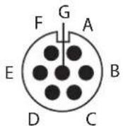
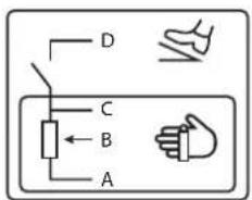
Beyond the manual remote control and the pedal, it is possible to create you own connectors using the optional male socket (ref. 045699). For the cabling layout, please see the diagram below utiliser a 10 kΩ potentiometer).
text_image
D C B Aref. 045699 External view Electric diagram according to the remote control type.
COOLING FAN
To minimise sound and dust aspiration, the station integrates a controlled fan system. The fan's rotation speed depends on the temperature and the machine's settings.
LOCKING CONTROLS
That feature can lock the knobs and keypad to prevent accidental changes in the settings.
Operation :
Press the button 🔒 for 3 seconds, the display shows Loc. and goes back to current display. The LED (FIG-2, n°11) switches on. No button is enabled, the secondary knob is disabled, the main knob can adjust the value at +/- of the percentage, defined by the «tolerance» setting tol. (see chapter «Access to menus»).
To unlock the commands, press the button for 3 seconds, the display shows Un Loc then goes back to current display. The LED (FIG-2, n°11) switches off.
ACCESS TO MENUS
flowchart
graph TD
    A["SET UP"] --> B["+ x3s"]
    B --> C["+ Buttons' release"]
    C --> D["Pr Out"]
    D --> E["Out: 01 ... Out: 50"]
    E --> F["Load settings and menu exit"]
    D --> G["Pr In"]
    G --> H["In: 01 ... In: 50"]
    H --> I["Save settings and menu exit"]
    D --> J["Con FIG"]
    J --> K["Current process settings menu"]
    K --> L["Exit settings menu"]
    L --> M["ToL Current value"]
    M --> N["ToL 300... ToL 100"]
    N --> O["Validate tolerance settings and back to root menu"]
    M --> P["InI ALL"]
    P --> Q["InI: 3 1s 1s 2 1"]
    Q --> R["Reset all settings for all processes"]
    S["Welding MMI output"] --> T["←"]
flowchart
graph TD
    A["Back to Setup menu"] --> B["Hot Start"]
    B --> C["Current value: HS 00 H5 100"]
    B --> D["Hot Start time: HST Current value: HST 00 HST 20"]
    B --> E["AntiSticking: AST Current value: AST On AST OFF"]
    B --> F["Frequency (MMA vertical up): FrE Current value: FrE 05 FrE 200"]
    B --> G["Percentage (MMA vertical up): Prc Current value: Prc 10 Prc 80"]
    G --> H["Init. Inl. 3 1s 1s 2 1"]
    H --> I["Reset current setting"]
    I --> J["Validate current setting"]
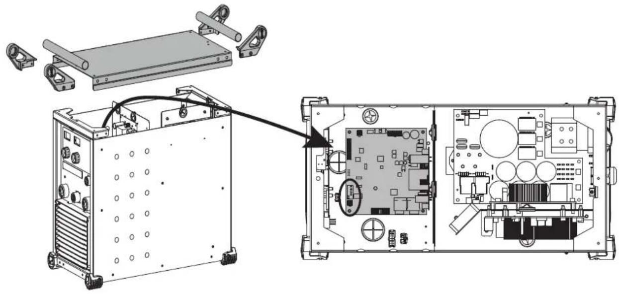
VOLTAGE REDUCTION DEVICE (VRD - PAGE 93)
The voltage reducing device (or VRD) reduces the no-load voltage allocated to a level not exceeding 35 V when the resistance of the external welding circuit exceeds 200 Ω. The reaction time is less than 300 ms. By default, the reducing device is disabled. In order to enable it, the user must open the product and follow the following procedure:
- Unplug the product from the mains and wait 5 minutes for safety.
- Remove the 3 screws from each handle support (1 on top and 2 on the side) = 4x3 screws.
- Remove the 4 handle holders and the 2 tubes.
- Remove the 2 remaining centre screws from the cover.
- Carefully remove the cover and disconnect the ground wire connected under the case.
- Locate the control board and the red switch (see page 93).
- Toggle switches 1 and 2 (default ON position) to the opposite position.
- Put the unit back together.
- Switch on the product, the device is active and the «VRD» LED on the keypad lights up.
TROUBLESHOOTING
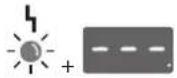
This device integrates a default management system. In the event of a default, error messages may be displayed.
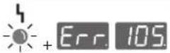
| Error code Signification CAUSES SOLUTIONS | |||
 | Thermal protection | Duty cycle excessed.Ambient temperature above 40°C.Obstructed air input. | Wait for the indicator to turn off before resuming welding operations.Oserve the duty cycle and insure a good ventilation.Using the optional anti dust filter will reduce the duty cycle. |
 | Mains voltage default. | Mains power is out of range or one phase is missing. | Have your electrical installation checked by a qualified person. The voltage between the phases must be between 340V RMS and 460V RMS. |
 | Current sensor default The current sensor is inactive or faulty. | Have the sensor's connection cables checked by a qualified person. | |
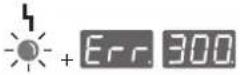 | Power relay command default. | The power relay could not be closed. | Have the relay's command connection cables checked by a qualified person. |
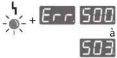 | No temperature information. | The temperature sensor is off. | Have the sensors' connection cables checked by a qualified person. |


Fan default.
One of the fans is not rotating at the right speed.
Check that there is no foreign object obstructing the fan, check the cabling, replace the fan.
All operations requiring the removal of the machine's cover and checking the electrical systems must be done by a qualified technician.
WARRANTY
The warranty covers faulty workmanship for 2 years from the date of purchase (parts and labour).
The warranty does not cover:
- Transit damage.
- Normal wear of parts (eg. : cables, clamps, etc..).
- Damages due to misuse (power supply error, dropping of equipment, disassembling).
- Environment related failures (pollution, rust, dust).
In case of failure, return the unit to your distributor together with: - The proof of purchase (receipt etc ...)
- A description of the fault reported
text_image
Diagram illustrating human posture with a 30° angle measurement and hand positioning on a chairtext_image
VRD V 160 A 9 -9 +9 MMA MIGTIG Gouging Reset 240 Reset 240 Lock MOCK OFF/ON/OFF RIF/ON/OFF RIF/ON/OFF RIF/ON/OFF RIF/ON/OFF RIF/ON/OFF RIF/ON/OFF RIF/ON/OFF RIF/ON/OFF RIF/ON/OFF RIF/ON/OFF RIF/ON/OFF RIF/ON/OFF RIF/ON/OFF RIF/ON/OFF RIF/OSI/OFF RIF/OSI/OFF RIF/OSI/OFF RIF/OSI/OFF RIF/OSI/OFF RIF/OSI/OFF RIF/OSI/OFF RIF/OSI/OFF RIF/OSI/OFF RIF/OSI/OFF RIF/OSI/OFF RIF/OSI/OFF RIF/OSI/OFF SOPP BUTORYtext_image
Diagram illustrating human posture with a 30° angle measurement and hanging object, showing two silhouettes.text_image
VRD V 160 A MMA MIGTIG Goeging Back 2024 Reset OFF Clock MODE 9 19 RESET/RESET setup memorytext_image
VID V 160 A MMA MIGTIG Gouging Back SOLD Risks Cell/lock SOLD MODE ACCPONE INJECTORS 9 19 pre-lipus3p setup memorytext_image
VRD V 160 A 3 -9 +9 MMA ANG TIG Gouging MODE power setup powertext_image
MMA MIG TIG Gouging MODEtext_image
25.0 VVD A 0 9 10 GSETS MMR MIG TIG GOUING MODE music setup memorytext_image
46.0 VRD V A FROTS MMA MIGTIG Goupling MODE setup memorytext_image
Diagram illustrating human posture with a 30° angle measurement and a chair-like structure, likely for motion or positioning reference.text_image
VRD V 160 A OFF: MMA MIG TIG Goeging Back 2018 MIP* Couch back 2012 MODE 9 -9 power setup memorytext_image
V80 V A MMA MIG TIG Gougingtext_image
46.0 V A MMA MIG TIG Goupling MOICE setup memoryWAARSCHUWING - VEILIGHEIDSINSTRUCTIES
ALGEMENE INSTRUCTIES

text_image
Diagram illustrating human posture with a 30° angle measurement and a chair-like structure, likely for safety or safety instructions.INSTALLATIE VAN HET APPARAAT
INTERFACE HUMANE MACHINE (IHM) (FIG-2)
1- Display spanning 13- Knop activeren afstandsbediening
2- Indicateur werking risicobeperkend systeem.
3- Display stroom 15- Indicator basische elektrode
4- Indicatielampje oververhitting 16- Indicator rutiele elektrode
5- Indicatielampje storing
6- Draaiknop hoofdinstellingen
7- Indicatielampje Arc-force
8- Indicatielampje variabele inductantie-instelling
9- Oplichtende cursor
10- Draaiknop secondaire instelling
11- Indicatielampje bedieningsvergrendeling
12- Knop bedieningsvergrendeling
text_image
VRD V 160 A 9 -9 -9 MMA MIGTIG Gouaging Back DOUT Button DOUT Cathodeck DOUT MODE STOP: setup memory prime Log workstext_image
VRD V 160 A MMA MIGTIG Gouging OFF Ruler 2012 Cellulink + - ANODE -9 -9 RESET/RESET setup memorytext_image
V80 V A photo 1s MMA MIG TIG Gouging MOCKtext_image
25.0 VRD V A 0 -9 +9 MMA MIG TIG Gouging MODE push setup memorytext_image
Diagram illustrating human posture with a 30° angle measurement and a chair arrangement, accompanied by a silhouette of two figures.text_image
VDD V 160 A MMA MIGTIG Goaging Back 2024 Reset 2024 Lock 2024 MODEL MOOD 9 9 8 8 8 UPPONE UPPONE UPPONE UPPONE UPPONE UPPONE UPPONE UPPONE UPPONE UPPONE UPPONE UPPONE UPPONE UPPONE UPPONE UPPONE UPPONE UPPONE UPPONE UPPONE UPPONE UPPONE UPPONE UPPONE UPPONE UPPON UPPON UPPON UPPON UPPON UPPON UPPON UPPON UPPON UPPON UPPON UPPON UPPON UPPON UPPON UPPON UPPON UPPON UPPON UPPON UPPON UPPON UPPON UPPON UPPON UPPONE UPPONE UPPONE UPPONE UPPONE UPPONE UPPONE UPPONE UPPONE UPPONE UPPONE UPPONE UPPONE UPPONE UPPONE UPPONE UPPONE UPPONE UPPONE UPPONE UPPONE UPPONE UPPONE UPPONE UPPOPENtext_image
VRD V 160 A MMA MIGTIG Gouging Back 2012 Bri Model MODEL PRELIPED model setup memorytext_image
V80 V A Pcno 3s MMA MIG TIG Gouging MOCKtext_image
Diagram illustrating a 30-degree angle measurement setup with two human silhouettes and a hanging frame structure.SPAWANIE ELEKTRODA OTULONA (TRYB MMA I MMA ROSNACE
PODŁACZENIE I PORADY
text_image
VRD V 160 A MMA MIG TIG Gouging Rosa 2018 Rafite 2018 Cathode 2018 MDC pcs Mats setup batterytext_image
VID V 160 A MMA MIG TIG Gouging Rout 2018 Rout 2019 Circuit 2019 MODE ACCPONE INVESTORS 9 19 Pots setup memorytext_image
VRD V 160 A 9 +9 +9 MMA MIG TIG Gauging MODEL results setup inventoryWYBÓR TRYBU I USTAWIENIE
text_image
p600s MMA MNG TIG Gouging MODEWYBÓR TRYBU I USTAWIENIE
WYBÓR TRYBU I USTAWIENIE
text_image
46.0 V A MMA MIGTIG Gouging MODE prelegn stop Ridingtext_image
Exploded view diagram of an electronic device with numbered components for assembly or maintenance reference.| 1 | Grille extérieure / External grill / Außengitter / Rejilla exterior / Внешняя решетка / Externe rooster / Griglia esterna / Kratka zewnętrzna | 56094 |
| 2 | Grille intérieure / Internal grill / Innengitter / Rejilla interior / Внутренняя решетка / Interne rooster / Griglia interna / Kratka wewnętrzna | 56095 |
| 3 | Ventilateurs / Fans / Lüfter / Ventiladores / Вентиляторы / Ventilatoren / Ventilatori / Wentylatory | 51290 |
| 4 | Diode / LED / Diode / Diodo / Диод / Diode / Diodo / Diodo 52197 | |
| 5 | Pied / Feet / Fuß / Pié / Ножка / Pootje / Piedino / Stopka 56120 | |
| 6 | Connecteur de puissance / Power relay connector / Schweißstrombuchse / Conector de potencia / Коннектор мощности / Stroom connector / Connettore di potenza / Złącze mocy | 51478 |
| 7 | Bouton de molette / Knob button / Drehknopf / Botón de ruedecilla / Поворотная кнопка / Draaiknop / Tasto della rotella / Przycisk pokrętła | 73016 |
| 8 | Clavier / Keypad / Display / Teclado / Панель управления / Bedieningspaneel / Tastiera / Klawiatura | 51963 |
| 9 | Carte d'affichage / Display circuit board / Displayplatine / Tarjeta de vídeo / Плата индикации / Videokaart / Scheda video / Karta graficzna | 97356C |
| 10 | Carte de contrôle puissance / Power control circuit board / Leistungssteuerplatine / Tarjeta de control de potencia / Плата контроля мощности / Vermogensbesturing kaart / Scheda di controllo della potenza / Karta kontroli mocy | 97358C |
| 11 | Carte d'alimentation basse tension / Low voltage supply circuit board / Niederspannungsplatine / Tarjeta de alimentación de baja tensión / Плата питания при низком напряжении / Laagspanning voedingskaart / Scheda di alimentazione a bassa tensione / Płyta zasilająca o niskim napięciu | 97288C |
| 12 | Pont de diodes / Diode bridge / Dioden-Brücke / Puente de diodos / Диодный мост / Diode brug / Ponte a diodi / Mostek diodowy | 52196 |
| 13 | Carte CEM / CEM board / CEM-Platine / Tarjeta CEM / Плата CEM / Printplaat / Scheda CEM / Karta EMC | 97277C |
| 14 | Carte de pilotage IGBT / IGBT control board / IGBT-Steuerplatine / Tarjeta de control IGBT / Плата управления IGBT / Besturingskaart IGBT / Scheda di comando IGBT / Karta sterowania IGBT | 97357C |
| 15 | Module IGBT / IGBT module / IGBT / Модуль IGBT / Módulo IGBT / IGBT Module / Modulo IGBT / Moduł IGBT | 52204 |
| 16 | Commutateur Marche/Arrêt / On/off switch / Ein-/Ausschalter / Conmutador Encendido/Apagado / Переключатель ВКЛ/ВЫКЛ / Schakelaar Aan/Uit / Commutatore Avvio/Arresto / Przełącznik ON / OFF | 51061 |
| 17 | Carte d'entrée puissance / Power input circuit board / Leistungsplatine / Tarjeta de entrada de potencia / Плата ввода мощности / Kaart ingangsvermogen / Scheda di entrata della potenza / Karta zasilania wejściowego | 97278C |
| 18 | Carte d'alimentation 24/48V / 24/48V power supply circuit board / Versorgungsplatine 24/48V / Tarjeta de alimentación 24/48V / Плата питания 24/48B / Voedingskaart 24/48V / Scheda di alimentazione 24/48V / Płyta zasilająca 24/48V | 97289C |
| Cordon secteur 4x4 mm ^2 - 5m / Power supply cable 4x4 mm ^2 - 5m / Netzleitung 4x4 mm ^2 - 5m / Cable de corriente 4x4 mm2 - 5m / Сетевой шнур 4x4 mm ^2 - 5m / Voedingskabel 4x4 mm ^2 - 5m / Cavo corrente 4x4 mm ^2 - 5m / Przewód zasilający 4x4 mm ^2 - 5m | 21470 |
INTERRUPTEUR VRD / VRD SWITCH / VRD-EIN-AUS-SCHALTER / INTERRUPTOR VRD / VRD SCHAKELAAR / INTERRUTTORE VRD / WYŁĄCZNIK VRD
natural_image
Technical diagram showing internal components of an electronic device, including a chassis and internal circuit board (no text or labels)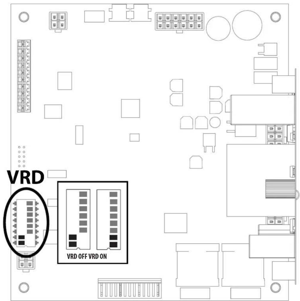
text_image
VRD VRD OFF VRD ONSCHÉMA ÉLECTRIQUE / CIRCUIT DIAGRAM / SCHALTPLAN / ESQUEMA ELÉCTRICO / ЭЛЕКТРИЧЕСКАЯ CXEMA / ELEKTRISCH SCHEMA / SCHEMA ELETTRICO / SCHEMAT ELEKTRYCZNY
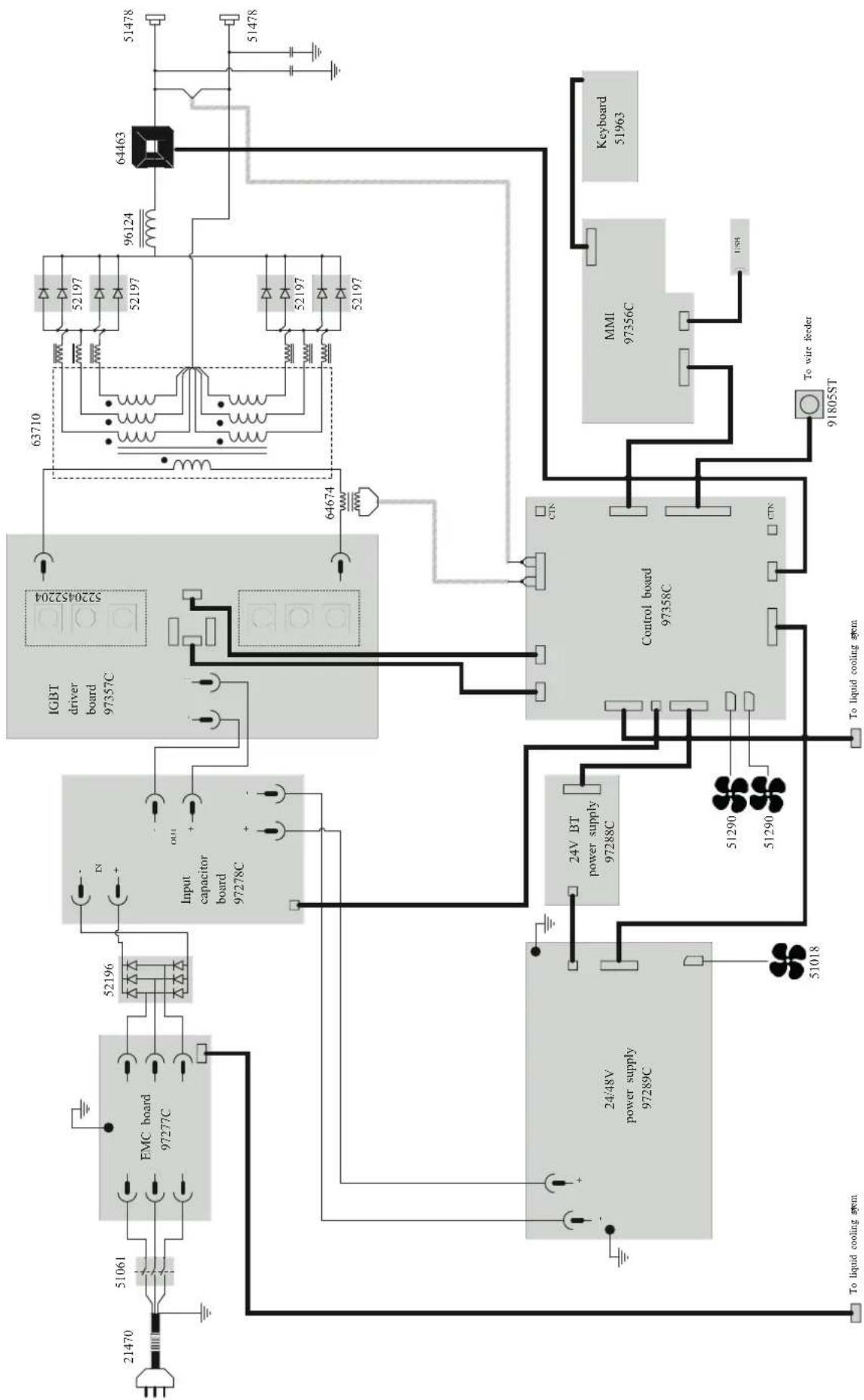
flowchart
graph TD
    A["21470"] --> B["51061"]
    B --> C["EMC board 97277C"]
    C --> D["52196"]
    D --> E["Input capacitor board 97278C"]
    E --> F["Control board 97358C"]
    F --> G["MMI 97356C"]
    G --> H["Keyboard 51963"]
    F --> I["To wire feeder 91805ST"]
    F --> J["To liquid cooling system"]
    F --> K["24V BT power supply 97288C"]
    K --> L["24/48V power supply 97289C"]
    L --> M["51018"]
    M --> N["51290"]
    N --> O["51290"]
    O --> P["51290"]
    P --> Q["51290"]
    Q --> R["51290"]
    R --> S["51290"]
    S --> T["51290"]
    T --> U["51290"]
    U --> V["51290"]
    V --> W["51290"]
    W --> X["51290"]
    X --> Y["51290"]
    Y --> Z["51290"]
    Z --> AA["51290"]
    AA --> AB["51290"]
    AB --> AC["51290"]
    AC --> AD["51290"]
    AD --> AE["51290"]
    AE --> AF["51290"]
    AF --> AG["51290"]
    AG --> AH["51290"]
    AH --> AI["51290"]
    AI --> AJ["51290"]
    AJ --> AK["51290"]
    AK --> AL["51290"]
    AL --> AM["51290"]
    AM --> AN["51290"]
    AN --> AO["51290"]
    AO --> AP["51290"]
    AP --> AQ["51290"]
    AQ --> AR["51290"]
    AR --> AS["51290"]
    AS --> AT["51290"]
    AT --> AU["51290"]
    AU --> AV["51290"]
    AV --> AW["51290"]
    AW --> AX["51290"]
    AX --> AY["51290"]
    AY --> AZ["51290"]
    AZ --> BA["51290"]
    BA --> BB["51290"]
    BB --> BC["51290"]
    BC --> BD["51290"]
    BD --> BE["51290"]
    BE --> BF["51290"]
    BF --> BG["51290"]
    BG --> BH["51290"]
    BH --> BI["51290"]
    BI --> BJ["51290"]
    BJ --> BK["51290"]
    BK --> BL["51290"]
    BL --> BM["51290"]
    BM --> BN["51290"]
    BN --> BO["51290"]
    BO --> BP["51290"]
    BP --> BQ["51290"]
    BQ --> BR["51290"]
    BR --> BS["51290"]
    BS --> BT["51290"]
    BT --> BU["51290"]
    BU --> BV["51290"]
    BV --> BW["51290"]
    BW --> BX["51290"]
    BX --> BY["51290"]
    BY --> BZ["51290"]
    BZ --> CA["51290"]
    CA --> CB["51290"]
    CB --> CC["51290"]
    CC --> CD["51290"]
    CD --> CE["51290"]
    CE --> CF["51290"]
    CF --> CG["51290"]
    CG --> CH["51290"]
    CH --> CI["51290"]
    CI --> CJ["51290"]
    CJ --> CK["51290"]
SPÉCIFICATIONS TECHNIQUES / TECHNICAL SPECIFICATIONS / TECHNISCHE DATEN / ESPECIFICACIONES TÉCNICAS/ TEXНИЧЕСКИЕ СПЕЦИФИКАЦИИ / TECHNISCHE GEGEVENS / SPECIFICHE TECNICHE / DANE TECHNICZNE
| EXAGON 400 CC/CV | |||
| Primaire / Primary / Primär / Primario / Первичka / Primaire / Primario / Podstawowy | |||
| Tension d'alimentation / Power supply voltage / Versorgungsspannung / Tensión de red eléctrica / Напряжение питания / Voedingss- panning / Tensione di alimentazione / Napięcie zasilania | 400 V +/- 15% | ||
| Fréquence secteur / Mains frequency / Netzfrequenz / Frecuencia / Частота сети / Frequentie sector / Frequenza settore / Częstotliwość sieci zasilania | 50 / 60 Hz | ||
| Nombre de phases / Number of phases / Anzahl der Phasen / Número de fases / Количество фаз / Aantal fasen / Numero di fase / Liczba faz | 3 | ||
| Fusible disjoncteur / Fuse / Sicherung / Fusible disyuntor / Плавкий предохранитель прерывателя / Zekering hoofdschakelaar / Fusibile disgiuntore / Wyłącznik bezpieczników | 32 A | ||
| Courant d'alimentation effectif maximal I1eff / Maximum effective supply current I1eff / Corriente de alimentación efectiva máxima I1eff / Maximale effectieve voedingsstroom I1eff / Corrente di alimentazione effettiva massima I1eff / Maksymalny efektywny prąd zasilania I1eff | 32 A | ||
| Courant d'alimentation maximal I1max / Maximum supply current I1max / Corriente de alimentación máxima I1max / Maximale voe- dingsstroom I1max / Corrente di alimentazione massima I1max / Maksymalny prąd zasilania I1max | 38 A | ||
| Section du cordon secteur / Mains cable section / Sectie netsnoer / Sección del cable de alimentación / Sezione del cavo di alimenta- zione / Odcinek przewodu zasilającego | 4 x 4 mm2 | ||
| Puissance active maximale consommée / Maximum active power consumed / Consumo máximo de energía activa / Maximale actieve verbruikte vermogen / Potenza attiva massima consumata / Maksymalny pobór mocy czynnej | 16 223 W | ||
| Consommation au ralenti / Idle consumption / Consumo en ralentizado / Stationair verbruik / Consumo al minimo / Zużycie na biegu jałowym | 30 W | ||
| Rendement à I2max / Efficiency at I2max / Eficiencia a I2máx / Rendement bij I2max / Efficienza a I2max / Sprawność przy I2max | 88.7 % | ||
| Facteur de puissance à I2max (λ) / Power factor at I2max (λ) / Factor de potencia a I2max (λ) / Inschakelduur bij I2max (λ) / Ciclo di potenza a I2max (λ) / Współczynnik mocy przy I2max (λ) | 0.62 | ||
| Classe CEM / EMC class / Classe CEM / Klasse CEM / Classe CEM / Klasa EMC A | |||
| Secondaire / Secondary / Sekundär / Secundario / Вторичка / Secondair / Secondario / Zapasowy | MMA SMAW | MIG / MAG GMAW | TIG GTAW |
| Tension à vide / No load voltage / Leerlaufspannung / Tensión al vacío / Напряжение холостого хода / Nullastspanning / Tensione a vuoto / Napięcie próżniowe | 84 V | ||
| Nature du courant de soudage / Type of welding current / Tipo de corriente de soldadura / Type lasstroom / Tipo di corrente di salda- tura / Rodzaj prądu spawania | DC | ||
| Modes de soudage / Welding modes / Modos de soldadura / Lasmodules / Modalità di saldatura / Tryby spawania | MMA, MIG-MAG, TIG | ||
| Courant de soudage minimal / Minimum welding current / Corriente mínima de soldadura / Minimale lasstroom / Corrente mínima di saldatura / Minimalny prąd spawania | 20 A 15 A 10 | A | |
| Courant de sortie nominal (I1) / Rate current output (I1) / nominaler Arbeitsstrom (I2) / Corriente de salida nominal (I) / Номинальный выходной ток (I2) / Nominaly uitgangsstroom (I3) / Corrente di uscita nominale (I2) / Nominalny prąd wyjściowy (I2) | 20 → 400 A 15 | +400 A 10 | +400 A |
| Tension de sortie conventionnelle (U1) / Conventional voltage output (U2) / entsprechende Arbeitsspannung (U3) / Условное выходные напряжения (U2) / Tensión de salida convencional (U2) / Conventionele uitgangsspanning (U2) / Tensione di uscita convenzionale (U2) / Konwencjonalne napięcie wyjściowe (U2) | 20.8 → 36 V 14.75 | +34 V 10.4 | +26 V |
| Facteur de marche à 40°C (10 min)*Norme IEC 60974-1.Duty cycle at 40°C (10 min)*Standard IEC 60974-1.Einschaltdauer @ 40°C (10 min)IEC 60974-1-NormCiclo de trabajo a 40°C (10 min)*Norma IEC 60974-1 | ПВ% при 40°C (10 мин)*Норма IEC 60974-1.Inschakelduur bij 40°C (10 min)*Norm IEC 60974-1.Ciclo di lavoro a 40°C (10 min)*Norma IEC 60974-1.Cykl pracy w 40°C (10 min)*Norma EN60974-1. | Imax 60 %60% 400 A100% 350 A | |
| Température de fonctionnement / Functionning temperature / Betriebstemperatur / Temperatura de funcionamiento / Рабочая температура / Gebruikstemperatuur / Temperatura di funzionamento / Temperatura urządzenia podczas pracy | -10°C ++40°C | ||
| Température de stockage / Storage temperature / Lagertemperatur / Temperatura de almacenaje / Температура хранения / Bewaar- temperatuur / Temperatura di stoccaggio / Temperatura przechowywania | -20°C ++55°C | ||
| Degré de protection / Protection level / Schutzart / Grado de protección / Степень защиты / Beschermingsklasse / Grado di protezione / Stopień ochrony | IP23 | ||
| Classe d'isolation minimale des enroulements / Minimum coil insulation class / Clase mínima de aislamiento del bobinado / Minimale isolatieklasse omwikkelingen / Classe mínima di isolamento degli avvolgimenti / Minimalna klasa izolacji okablowania | B | ||
| Dimensions (Lxbxh) / Dimensions (LxWxH) / Abmessungen (Lxbxt) / Dimensiones (Lxlxh) / Размеры (ДхШхВ) / Afmetingen (Lxlxh) / Dimensioni (Lxlxh) / Wymiary (DxSxW) | 58 x 30 x 52 cm | ||
| Poids / Weight / Gewicht / Bec / Peso / Gewicht / Peso / Waga 32 kg | |||
*The duty cycles are measured according to standard IEC 60974-1 à 40°C and on a 10 min cycle.
While under intensive use (> to duty cycle) the thermal protection can turn on, in that case, the arc swictes off and the indicator switches on. Keep the machine's power supply on to enable cooling until thermal protection cancellation. The current source has a falling output characteristic.