WWSS1332W - Office Tripp Lite - Free user manual and instructions
Find the device manual for free WWSS1332W Tripp Lite in PDF.

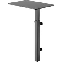
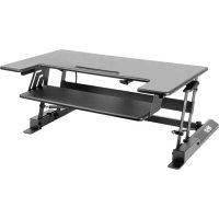
| Product Type | Sit-stand wall-mounted workstation for single monitor |
| Brand | Tripp Lite |
| Model | WWSS1332W |
| Material | Steel |
| Maximum load capacity | 15 kg (33 lb) |
| VESA compatibility | 75x75 mm and 100x100 mm |
| Tilt range | Adjustable |
| Rotation | Pivotable |
| Articulated arm | Yes, with tension adjustment |
| Keyboard shelf included | Yes, angle adjustable |
| Wall installation | Yes, on studs or concrete |
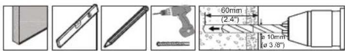
| Included tools | 4 mm and 6 mm hex keys |
| Warranty | 5 years |
| Maintenance and cleaning | Clean with a soft dry cloth |
| Safety | Check the mount every 3 months |
| Spare parts | Contact Tripp Lite for replacement parts |
| Repairability | Product repairable by a professional |
| General information | Designed for indoor use |
| Package dimensions | Not specified, approximately 60 x 30 x 15 cm |
| Package weight | Approximately 5 kg |
Frequently Asked Questions - WWSS1332W Tripp Lite
User questions about WWSS1332W Tripp Lite
0 question about this device. Answer the ones you know or ask your own.
Ask a new question about this device
Download the instructions for your Office in PDF format for free! Find your manual WWSS1332W - Tripp Lite and take your electronic device back in hand. On this page are published all the documents necessary for the use of your device. WWSS1332W by Tripp Lite.
USER MANUAL WWSS1332W Tripp Lite
natural_image
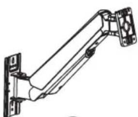
Line drawing of a mechanical arm with a vertical support and base plate (no text or symbols)Espanol 9 • Français 17 • Русский 25 • Deutsch 33

CAUTION: DO NOT EXCEED MAXIMUM LISTED WEIGHT CAPACITY (17.6 lb. / 8 kg). SERIOUS INJURY OR PROPERTY DAMAGE MAY OCCUR!
PROTECT YOUR INVESTMENT!
Register your product for quicker service and ultimate peace of mind. You could also win an ISOBAR6ULTRA surge protector—a \$100 value! www.tripplite.com/warranty


1111 W. 35th Street, Chicago, IL 60609 USA • www.tripplite.com/support
Copyright © 2017 Tripp Lite. All rights reserved.
Component Checklist

IMPORTANT: Ensure all parts according to the component checklist have been received prior to installation. If any parts are missing or faulty, visit www.triplite.com/support for service.
natural_image
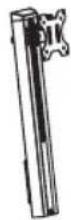
Technical line drawing of a mechanical arm or bracket assembly (no text or symbols)A
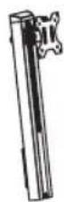
Bracket Arm
x1
B
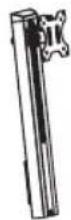
Support Mast
x1
natural_image
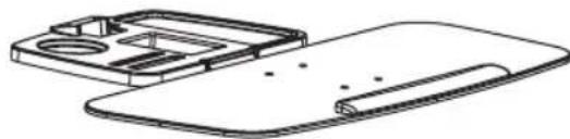
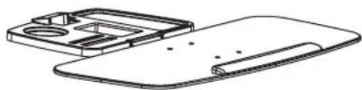
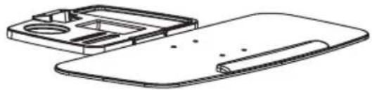
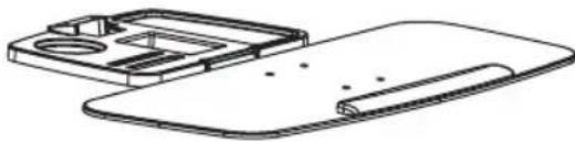
Technical line drawing of a mechanical housing or enclosure component (no text or symbols)C
Keyboard Shelf
x1

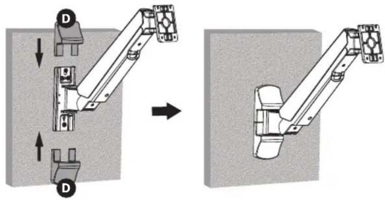
D
Decorative Cover
x2
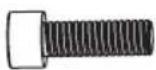
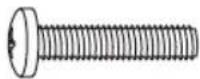
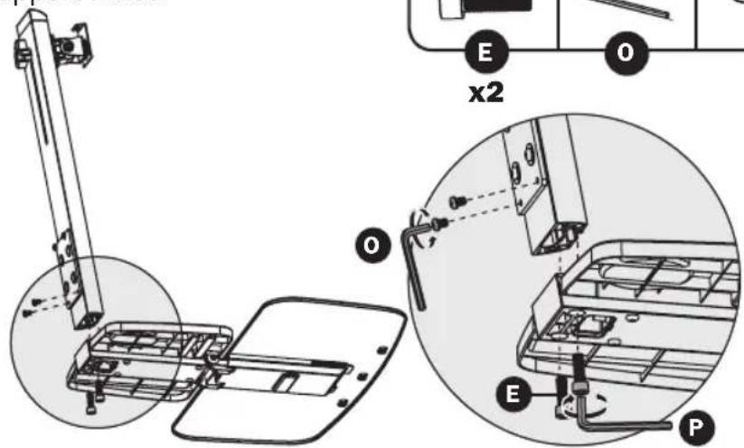
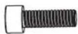
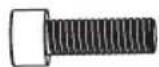
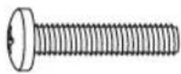
E
M8 x 25
x2
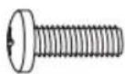
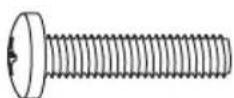
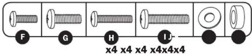
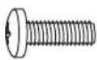
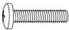
F
M4 x 12
x4
G
M5 x 12
x4
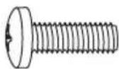
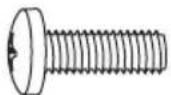
H
M4 x 16
x4
I
M5 x 16
x4

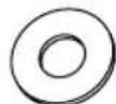
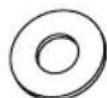
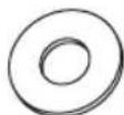
J
D5 Washer
x4
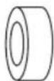
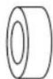
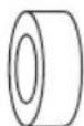
K
8 x 5 Spacer
x4
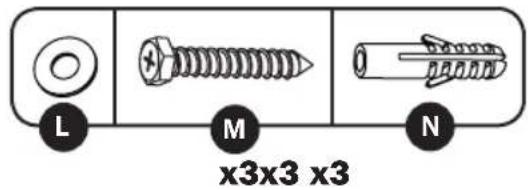
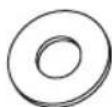
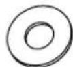
L
D6 Washer
[Non-Text]
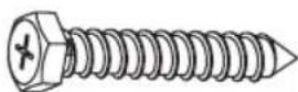
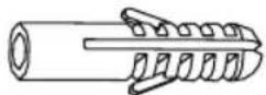
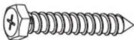
M
6.3 × 55
Tapping Screw
x7
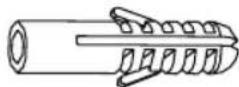
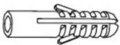
N
10 x 45 Anchor
x7
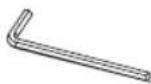
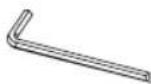
0
4 mm Hex Key
x1

P
6 mm Hex Key
x1
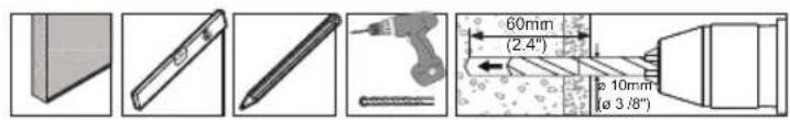
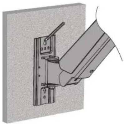
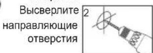
Assembly

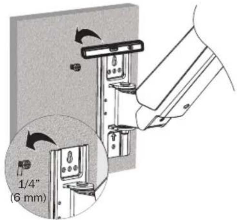
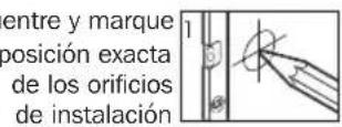
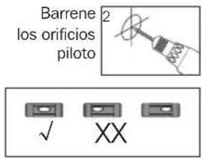
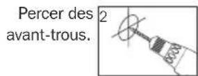
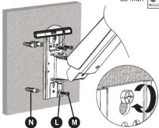
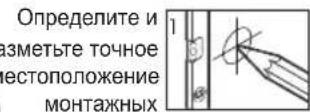
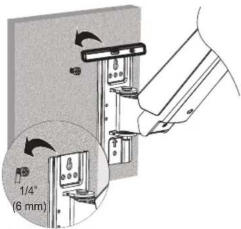
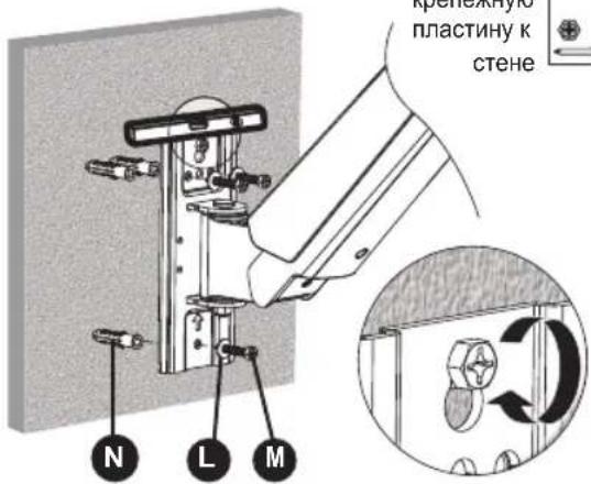
Mount Bracket Arm to wall.
natural_image
Technical illustration of a mechanical clamp or bracket assembly mounted on a wall, with no visible text or symbols.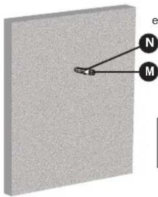
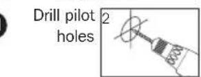
Screw the wall
mount onto
the wall
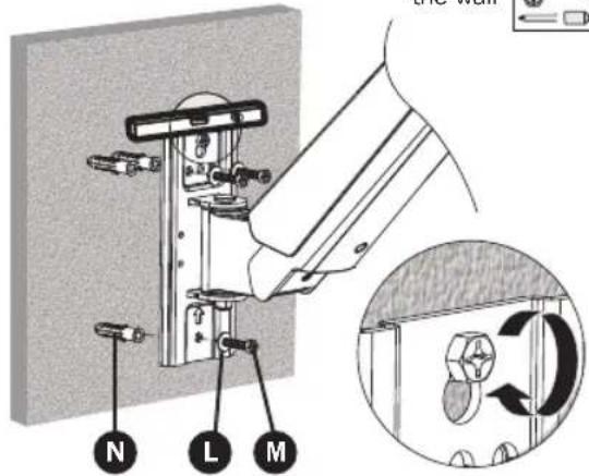
WARNING
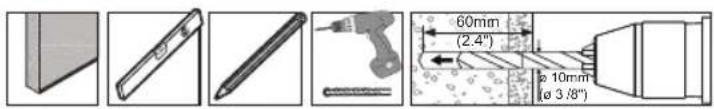
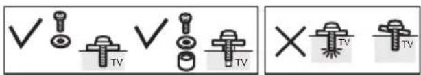
- When mounting on a wood stud wall, make sure that mounting screws are anchored into the center of the studs. Use of a stud finder is highly recommended.
- When installing wall mounts onto a concrete masonry unit (also known as a CMU or "cinder block"), verify that the actual concrete thickness is at least 35 mm (1-3/8") in order to hold the concrete anchors. DO NOT DRILL INTO MORTAR JOINTS! Be sure to mount the wall mount with the included concrete anchors and anchor bolts onto solid sections of the blocks. The solid sections can generally be found 25 mm (1") toward the middle of the block from either end. An electric drill on a slow setting is suggested to drill the hole rather than a hammer drill, so as to avoid breaking out the back of the hole when entering a hollow section.
• Installers are responsible to provide hardware for other types of mounting situations.
• Installers must verify that the supporting surface will safely support the combined load of the equipment and all attached hardware and components.
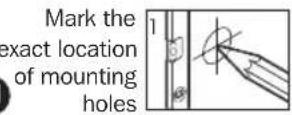
Assembly

Install Decorative Covers.
natural_image
Mechanical assembly diagram showing a robotic arm with two side-mounted joints, before and after assembly (no text or symbols present)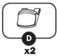

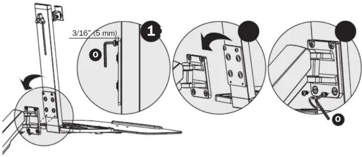
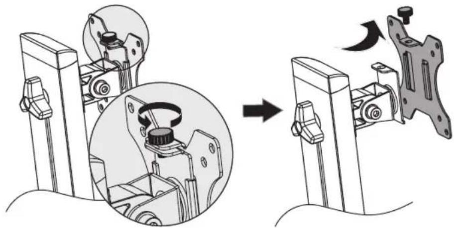
Remove VESA Plate from Support Mast.

natural_image
Mechanical assembly diagram showing a disassembly or assembly process with labeled parts and directional arrows (no text or symbols present)
Attach Keyboard Shelf to Support Mast.
4
Assembly

Attach Keyboard Shelf and Support Mast Assembly to Bracket Arm.

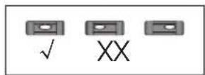
Attach VESA plate to back of display.


Note: Firmly secure the VESA plate to the display using the appropriate screws, washers and spacers (if necessary).

Do not over-tighten screws.
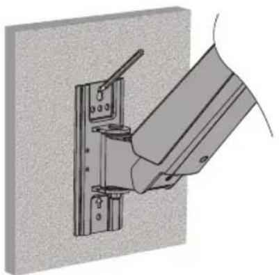
Assembly

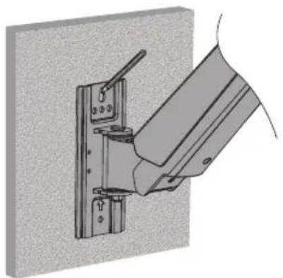
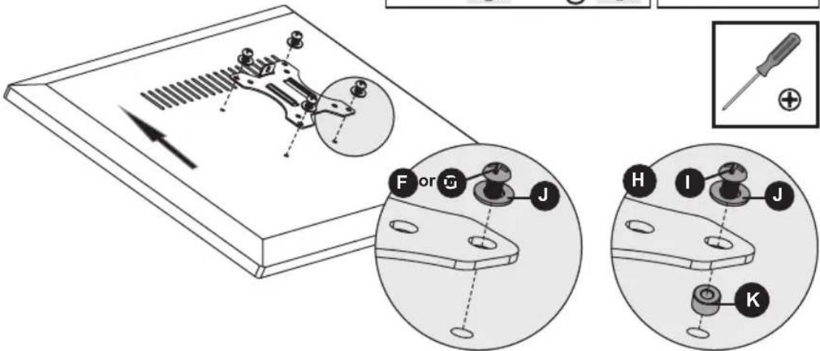
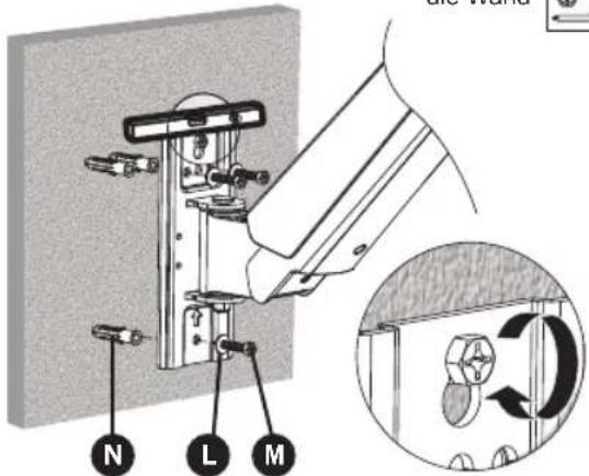
Slide VESA plate and Display onto the Support Mast.
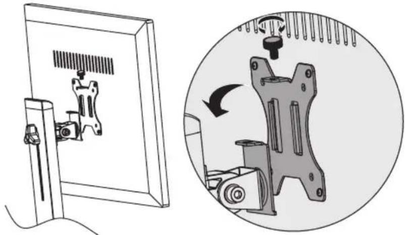
natural_image
Technical illustration showing a mounted device with a scroll wheel and a close-up of its mechanical component (no text or symbols present)
Using an assistant or mechanical lifting equipment, lift the display with attached VESA plate. Slide the VESA plate over the Support Mast bracket. Reattach the top knob to secure the VESA mount (removed in step 3).

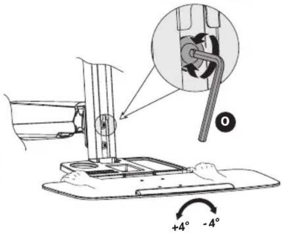
Adjust Bracket Arm tension.
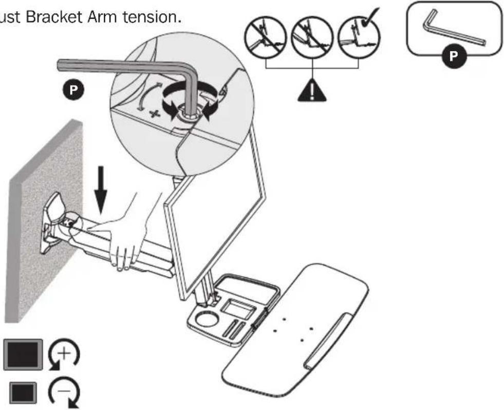
Keep the bracket arm level during tension adjustment. You may need to slightly loosen or tighten the adjustment screw using the provided 6 mm Hex Key, depending on the weight of display installed.
If display settles on its own, rotate adjustment screw towards the “+” symbol.
If display rises on its own, rotate adjustment screw towards the "-" symbol.
Adjust to the desired location or tilt.
+15° -15°
+4^ -4^
To correct the tilting angle, tighten the adjustment screws using the provided Hex Keys (or tighten the knob).
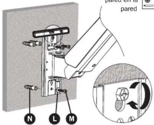
Keyboard Shelf adjusts at multiple angles.
0^
10^
10^
Assembly
Maintenance
- Check that the bracket is secure and safe to use at regular intervals (at least every three months).
- Please visit www.triplite.com/support if you have any questions.
Warranty and Product Registration
5-Year Limited Warranty
Seller warrants this product, if used in accordance with all applicable instructions, to be free from original defects in material and workmanship for a period of 5 years from the date of initial purchase. If the product should prove defective in material or workmanship within that period, Seller will repair or replace the product, in its sole discretion.
THIS WARRANTY DOES NOT APPLY TO NORMAL WEAR OR TO DAMAGE RESULTING FROM ACCIDENT, MISUSE, ABUSE OR NEGLECT. SELLER MAKES NO EXPRESS WARRANTIES OTHER THAN THE WARRANTY EXPRESSLY SET FORTH HEREIN. EXCEPT TO THE EXTENT PROHIBITED BY APPLICABLE LAW, ALL IMPLIED WARRANTIES, INCLUDING ALL WARRANTIES OF MERCHANTABILITY OR FITNESS, ARE LIMITED IN DURATION TO THE WARRANTY PERIOD SET FORTH ABOVE; AND THIS WARRANTY EXPRESSLY EXCLUDES ALL INCIDENTAL AND CONSEQUENTIAL DAMAGES. (Some states do not allow limitations on how long an implied warranty lasts, and some states do not allow the exclusion or limitation of incidental or consequential damages, so the above limitations or exclusions may not apply to you. This warranty gives you specific legal rights, and you may have other rights which vary from jurisdiction to jurisdiction).
WARNING: The individual user should take care to determine prior to use whether this device is suitable, adequate or safe for the use intended. Since individual applications are subject to great variation, the manufacturer makes no representation or warranty as to the suitability or fitness of these devices for any specific application.
PRODUCT REGISTRATION
Visit www.triplite.com/warranty today to register your new Tripp Lite product. You'll be automatically entered into a drawing for a chance to win a FREE Tripp Lite product!* * No purchase necessary. Void where prohibited. Some restrictions apply. See website for details.
Tripp Lite has a policy of continuous improvement. Specifications are subject to change without notice.


1111 W. 35th Street, Chicago, IL 60609 USA • www.tripplite.com/support
natural_image
Line drawing of a mechanical arm with a vertical support and base plate (no text or symbols)English 1 • Français 17 • Русский 25 • Deutsch 33

1111 W. 35th Street, Chicago, IL 60609 USA • www.tripplite.com/support
natural_image
Technical line drawing of a mechanical arm or bracket assembly (no text or symbols)A
Brazo de Soporte
x1
B
Mástil de Soporte
x1
natural_image
Technical line drawing of a mechanical housing or enclosure with internal components (no text or symbols)C
Repisa para Teclado
x1

D
Cubierta Decorativa
x2
E
M8 x 25
x2
F
M4 x 12
x4
G
M5 x 12
x4
H
M4 x 16
x4
I
M5 x 16
x4
J
Arandela D5
x4
K
Espaciador de 8 x 5
x4
L
Arandela D6 x3

M
Tornillo Autorroscantede 6.3 x 55
x7
N
Taquete de 10 x 45
x7

0
Llave Hexagonal de 4 mm
x1
P
Llave Hexagonal de 6 mm
x1
Ensamble


natural_image
Technical illustration of a mechanical assembly with a bracket and mounting bracket (no text or symbols)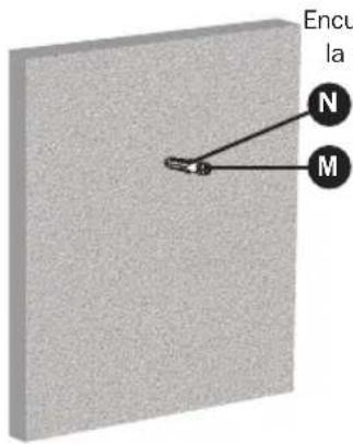
ADVERTENCIA
natural_image
Mechanical assembly diagram showing a robotic arm with two side-mounted joints, before and after assembly (no text or symbols present)

natural_image
Mechanical assembly diagram showing a disassembly or assembly process with labeled parts and directional arrows (no text or symbols present)
12
Ensamble


natural_image
Technical illustration showing a mounted device with a scroll wheel and a close-up of its mechanical component (no text or symbols present)
natural_image
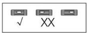
Two identical L-shaped tool icons labeled O and P, shown side by side within rounded rectangular frames (no text or symbols on the tools themselves)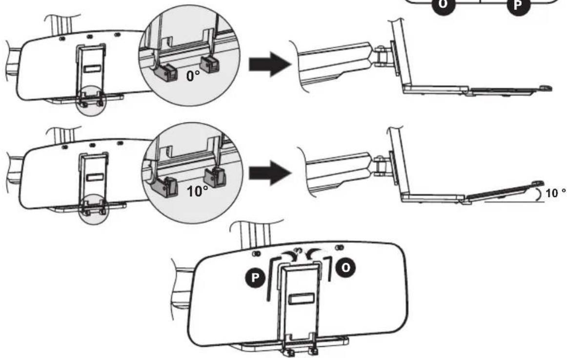
Ensamble
Mantenimiento
1111 W. 35th Street, Chicago, IL 60609 USA • www.tripplite.com/support
natural_image
Line drawing of a mechanical arm with a vertical support and base plate (no text or symbols)English 1 • Español 9 • Русский 25 • Deutsch 33

MISE EN GARDE : NE PAS EXCÉDER LA CAPACITÉ PONDÉRALE MAXIMUM INDIQUÉE (8 kg). DES BLESSURES GRAVES OU DES DOMMAGES MATÉRIELS RISQUENT DE SE PRODUIRE!


1111 W. 35th Street, Chicago, IL 60609 USA • www.tripplite.com/support
natural_image
Technical line drawing of a mechanical arm or linkage assembly (no text or symbols)A
Bras du support
x1
B
Mât de support
x1
natural_image
Technical line drawing of a mechanical housing or enclosure component (no text or symbols)C
Étagère du clavier
x1

D
Couvercle décoratif
x2
E
M8 x 25
x2
F
M4 x 12
x4
G
M5 × 12
x4
H
M4 x 16
x4
I
M5 x 16
x4
J
Rondelle D5
x4
K
Entretoise
8×5
x4
L
Rondelle D6
x3
M
Vis taraudeuse 6.3 x 55
x7
N
Ancrage 10 x 45
x7
0

natural_image
Technical illustration of a mechanical assembly with a bracket and mounting bracket (no text or symbols)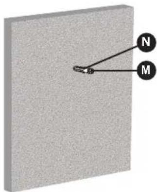
natural_image
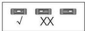
3D diagram of a rectangular block with labeled points M and N, showing internal structure (no text or symbols beyond labels)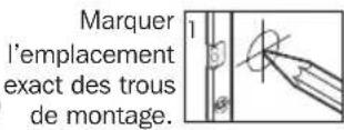
AVERTISSEMENT
natural_image
Mechanical assembly diagram showing a robotic arm with two side-mounted joints, before and after assembly (no text or symbols present)

Retirer la plaque VESA du mât du support.
natural_image
Mechanical assembly diagram showing a disassembly of a mechanical component into a housing (no text or labels present)
20
Assemblage


natural_image
Technical illustration showing a mounted device with a scroll wheel and a close-up of its internal mechanism (no text or symbols present)
natural_image
Two identical L-shaped tool icons labeled O and P, shown side by side within rounded rectangular frames (no text or symbols on the tools themselves)
Assemblage
Entretien
1111 W. 35th Street, Chicago, IL 60609 USA • www.tripplite.com/support
natural_image
Line drawing of a mechanical arm with a vertical support and base plate (no text or symbols)English 1 • Español 9 • Français 17 • Deutsch 33

1111 W. 35th Street, Chicago, IL 60609 USA • www.tripplite.com/support
natural_image
Technical line drawing of a mechanical arm or linkage assembly (no text or symbols)A
natural_image
Technical line drawing of a mechanical housing or enclosure with internal components (no text or symbols)C
natural_image
Technical illustration of a mechanical bracket assembly mounted on a wall, showing mounting holes and a handle (no text or symbols present)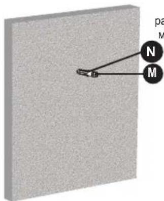
natural_image
Mechanical assembly diagram showing a robotic arm with two components, before and after assembly (no text or symbols)
3
natural_image
Mechanical assembly diagram showing a disassembly of a mechanical component into a housing (no text or symbols present)4
28
Сборка
natural_image
Technical illustration showing a mounted device with a rack and a close-up of its mechanical component (no text or symbols present)
Сборка
1111 W. 35th Street, Chicago, IL 60609 USA • www.tripplite.com/support
Benutzerhandbuch
TRIPP·LITE
WorkWise™
natural_image
Line drawing of a mechanical arm with a vertical support and base plate (no text or symbols)English 1 • Español 9 • Français 17 • Русский 25

1111 W. 35th Street, Chicago, IL 60609 USA • www.tripplite.com/support
natural_image
Technical line drawing of a mechanical arm or support structure (no text or symbols)A
Trägerarm
x1
B
Trägermast
x1
natural_image
Technical line drawing of a mechanical housing or enclosure component (no text or symbols)C
Tastaturablage
x1

D


natural_image
Technical illustration of a mechanical assembly with a bracket and mounting bracket (no text or symbols)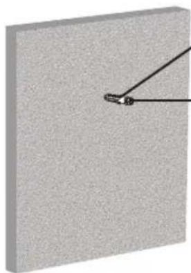
natural_image
3D rendering of a gray rectangular block with a black diagonal line extending from its top edge (no text or symbols)N
M
WARNUNG
natural_image
Mechanical assembly diagram showing a robotic arm with two side-mounted joints, before and after assembly (no text or symbols present)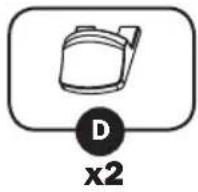

natural_image
Mechanical assembly diagram showing a disassembly or assembly process with labeled parts and directional arrows (no text or symbols present)
36
Montage


natural_image
Technical illustration showing a mounted device and its internal mechanical assembly with rotation arrows (no text or symbols)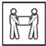
Montage
Wartung
1111 W. 35th Street, Chicago, IL 60609 USA • www.tripplite.com/support